Automated CT Lung Cancer Screening Workflow using 3D Camera
Abstract
Despite recent developments in CT planning that enabled automation in patient positioning, time-consuming scout scans are still needed to compute dose profile and ensure the patient is properly positioned. In this paper, we present a novel method which eliminates the need for scout scans in CT lung cancer screening by estimating patient scan range, isocenter, and Water Equivalent Diameter (WED) from 3D camera images. We achieve this task by training an implicit generative model on over 60,000 CT scans and introduce a novel approach for updating the prediction using real-time scan data. We demonstrate the effectiveness of our method on a testing set of 110 pairs of depth data and CT scan, resulting in an average error of in estimating the isocenter, in determining the scan range, and in estimating the AP and lateral WED respectively. The relative WED error of our method is , which is well within the International Electrotechnical Commission (IEC) acceptance criteria of .
Keywords:
CT Lung Screening Dose WED 3D Camera1 Introduction
Lung cancer is the leading cause of cancer death in the United States, and early detection is key to improving survival rates. CT lung cancer screening is a low-dose CT (LDCT) scan of the chest that can detect lung cancer at an early stage, when it is most treatable. However, the current workflow for performing CT lung scans still requires an experienced technician to manually perform pre-scanning steps, which greatly decreases the throughput of this high volume procedure. While recent advances in human body modeling [12, 4, 13, 5, 15] have allowed for automation of patient positioning, scout scans are still required as they are used by automatic exposure control system in the CT scanners to compute the dose to be delivered in order to maintain constant image quality [3].
Since LDCT scans are obtained in a single breath-hold and do not require any contrast medium to be injected, the scout scan consumes a significant portion of the scanning workflow time. It is further increased by the fact that tube rotation has to be adjusted between the scout and actual CT scan. Furthermore, any patient movement during the time between the two scans may cause misalignment and incorrect dose profile, which could ultimately result in a repeat of the entire process. Finally, while minimal, the radiation dose administered to the patient is further increased by a scout scan.
We introduce a novel method for estimating patient scanning parameters from non-ionizing 3D camera images to eliminate the need for scout scans during pre-scanning. For LDCT lung cancer screening, our framework automatically estimates the patient’s lung position (which serves as a reference point to start the scan), the patient’s isocenter (which is used to determine the table height for scanning), and an estimate of patient’s Water Equivalent Diameter (WED) profiles along the craniocaudal direction which is a well established method for defining Size Specific Dose Estimate (SSDE) in CT imaging [8, 9, 18, 11]. Additionally, we introduce a novel approach for updating the estimated WED in real-time, which allows for refinement of the scan parameters during acquisition, thus increasing accuracy. We present a method for automatically aborting the scan if the predicted WED deviates from real-time acquired data beyond the clinical limit. We trained our models on a large collection of CT scans acquired from over patients from over 15 sites across North America, Europe and Asia. The contributions of this work can be summarized as follows:
-
•
A novel workflow for automated CT Lung Cancer Screening without the need for scout scan
-
•
A clinically relevant method meeting IEC 62985:2019 requirements on WED estimation.
-
•
A generative model of patient WED trained on over patients.
-
•
A novel method for real-time refinement of WED, which can be used for dose modulation
2 Method
Water Equivalent Diameter (WED) is a robust patient-size descriptor [17] used for CT dose planning. It represents the diameter of a cylinder of water having the same averaged absorbed dose as the material contained in an axial plane at a given craniocaudal position [2]. The WED of a patient is thus a function taking as input a craniocaudal coordinate and outputting the WED of the patient at that given position. As WED is defined in an axial plane, the diameter needs to be known on both the Anterior-Posterior (AP) and lateral (Left- Right) axes noted respectively and . As our focus here is on lung cancer screening, we define ‘WED profile’ to be the 1D curve obtained by uniformly sampling the WED function along the craniocaudal axis within the lung region. Our method jointly predicts the AP and lateral WED profiles.
While WED can be derived from CT images, paired CT scans and camera images are rarely available, making direct regression through supervised learning challenging. We propose a semi-supervised approach to estimate WED from depth images. First, we train a WED generative model on a large collection of CT scans. We then train an encoder network to map the patient depth image to the WED manifold. Finally, we propose a novel method to refine the prediction using real-time scan data.
2.1 WED Latent Space Training
We use an AutoDecoder [10] to learn the WED latent space. Our model is a fully connected network with 8 layers of 128 neurons each. We used layer normalization and ReLU activation after each layer except the last one. Our network takes as input a latent vector together with a craniocaudal coordinate and outputs and , the values of the AP and lateral WED at the given coordinate. In this approach, our latent vector represents the encoding of a patient in the latent space. This way, a single AutoDecoder can learn patient-specific continuous WED functions. Since our network only takes the craniocaudal coordinate and the latent vector as input, it can be be trained on partial scans of different sizes. The training consists of a joint optimization of the AutoDecoder and the latent vector: the AutoDecoder is learning a realistic representation of the WED function while the latent vector is updated to fit the data.
During training, we initialize our latent space to a unit Gaussian distribution as we want it to be compact and continuous. We then randomly sample points along the craniocaudal axis and minimize the L1 loss between the prediction and the ground truth WED. We also apply L2-regularization on the latent vector as part of the optimization process.
2.2 Depth Encoder Training
After training our generative model on a large collection of unpaired CT scans, we train our encoder network on a smaller collection of paired depth images and CT scans. We represent our encoder as a DenseNet [1] taking as input the depth image and outputting a latent vector in the previously learned latent space. Our model has 3 dense blocks of 3 convolutional layers. Each convolutional layer (except the last one) is followed by a spectral normalization layer and a ReLU activation. The predicted latent vector is then used as input to the frozen AutoDecoder to generate the predicted WED profiles. We here again apply L2-regularization on the latent vector during training.
2.3 Real-time WED Refinement
While the depth image provides critical information on the patient anatomy, it may not always be sufficient to accurately predict the WED profiles. For example, some patients may have implants or other medical devices that cannot be guessed solely from the depth image. Additionally, since the encoder is trained on a smaller data collection, it may not be able to perfectly project the depth image to the WED manifold. To meet the strict safety criteria defined by the IEC, we propose to dynamically update the predicted WED profiles at inference time using real-time scan data. First, we use our encoder network to initialize the latent vector to a point in the manifold that is close to the current patient. Then, we use our AutoDecoder to generate initial WED profiles. As the table moves and the patient gets scanned, CT data is being acquired and ground truth WED can be computed for portion of the body that has been scanned, along with the corresponding craniocaudal coordinate. We can then use this data to optimize the latent vector by freezing the AutoDecoder and minimizing the L1 loss between the predicted and ground truth WED profiles through gradient descent. We can then feed the updated latent vector to our AutoDecoder to estimate the WED for the remaining portions of the body that have not yet been scanned and repeat the process.
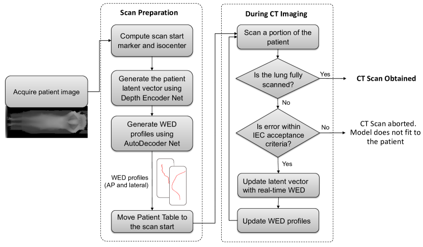
In addition to improving the accuracy of the WED profiles prediction, this approach can also help detect deviation from real data. After the latent vector has been optimized to fit the previously scanned data, a large deviation between the optimized prediction and the ground truth profiles may indicate that our approach is not able to find a point in the manifold that is close to the data. In this case, we may abort the scan, which further reduces safety risks. Overall flowchart of the proposed approach is shown in Figure 1.
3 Results
3.1 Data
Our CT scan dataset consists of patients from different sites across North America, Asia and Europe. Our 3D Camera dataset consists of pairs of depth image and CT scan from patients from different sites across North America and Europe acquired using a ceiling-mounted Kinect 2 camera. Our evaluation set consists of pairs of depth image and CT scan from patients from a separate site in Europe.
3.2 Patient preparation
Patient positioning is the first step in lung cancer screening workflow. We first need to estimate the table position and the starting point of the scan. We propose to estimate the table position by regressing the patient isocenter and the starting point of the scan by estimating the location of the patient’s lung top.
3.2.1 Starting position
We define the starting position of the scan as the location of the patient’s lung top. We trained a DenseUNet [7] taking the camera depth image as input and outputting a Gaussian heatmap centered at the patient’s lung top location. We used 4 dense blocks of 4 convolutional layers for the encoder and 4 dense blocks of 4 convolutional layers for the decoder. Each convolutional layer (except the last one) is followed by a batch normalization layer and a ReLU activation. We trained our model on patients using Adaloss [14] and the Adam [6] optimizer with a learning rate of and a batch size of for 400 epochs. Our model achieves a mean error of 12.74mm and a percentile error of 28.32mm. To ensure the lung is fully visible in the CT image, we added a offset on our prediction towards the outside of the lung. We then defined the accuracy as whether the lung is fully visible in the CT image when using the offset prediction. We report an accuracy of 100% on our evaluation set of patients.
3.2.2 Isocenter
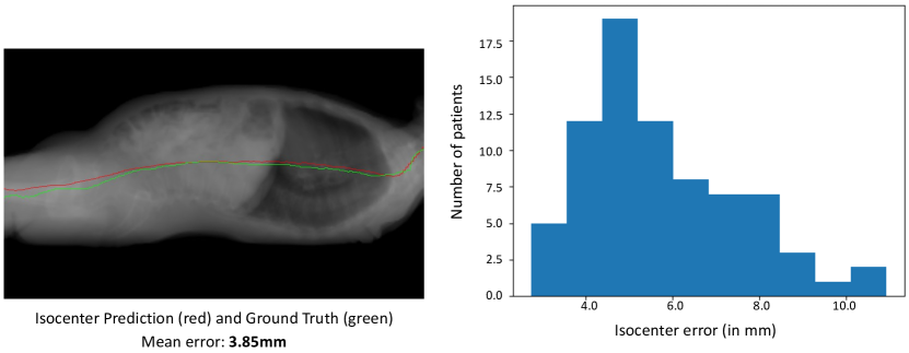
The patient isocenter is defined as the centerline of the patient’s body. We trained a DenseNet [1] taking the camera depth image as input and outputting the patient isocenter. Our model is made of 4 dense blocks of 3 convolutional layers. Each convolutional layer (except the last one) is followed by a batch normalization layer and a ReLU activation. We trained our model on patients using Adadelta [16] with a batch size of for 300 epochs. On our evaluation set, our model outperforms the technician’s estimates with a mean error of 5.42mm and a percentile error of 8.56mm compared to mm and mm respectively. Results can be seen in Figure 2.
3.3 Water Equivalent Diameter
| Method (lateral) | Mean error | 90th perc error | Max error |
|---|---|---|---|
| Direct Regression | |||
| Proposed (initial) | |||
| Proposed (refined, ) | |||
| Proposed (refined, ) | 15.93 | 35.93 | 61.68 |
| Method (AP) | |||
| Direct Regression | |||
| Proposed (initial) | |||
| Proposed (refined, ) | |||
| Proposed (refined, ) | 10.40 | 22.44 | 33.85 |
We trained our AutoDecoder model on our unpaired CT scan dataset of patients with a latent vector of size 32. The encoder was trained on our paired CT scan and depth image dataset of patients. We first compared our method against a simple direct regression model. We trained a DenseUNet [7] taking the camera depth image as input and outputting the Water Equivalent Diameter profile. We trained this baseline model on patients using the Adadelta [6] optimizer with a learning rate of and a batch size of . We then measured the performance of our model before and after different degrees of real-time refinement, using the same optimizer and learning rate. We report the comparative results in Table 1.
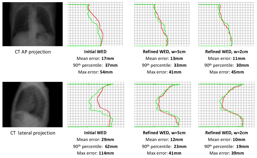
We observed that our method largely outperforms the direct regression baseline with a mean lateral error 40% lower and a percentile lateral error over 30% lower. Bringing in real-time refinement greatly improves the results with a mean lateral error over 40% and a percentile lateral error over 20% lower than before refinement. AP profiles show similar results with a mean AP error improvement of nearly 40% and a percentile AP error improvement close to 30%. When using our proposed method with a window refinement, our proposed approach outperforms the direct regression baseline by over 60% for lateral profile and nearly 80% for AP.
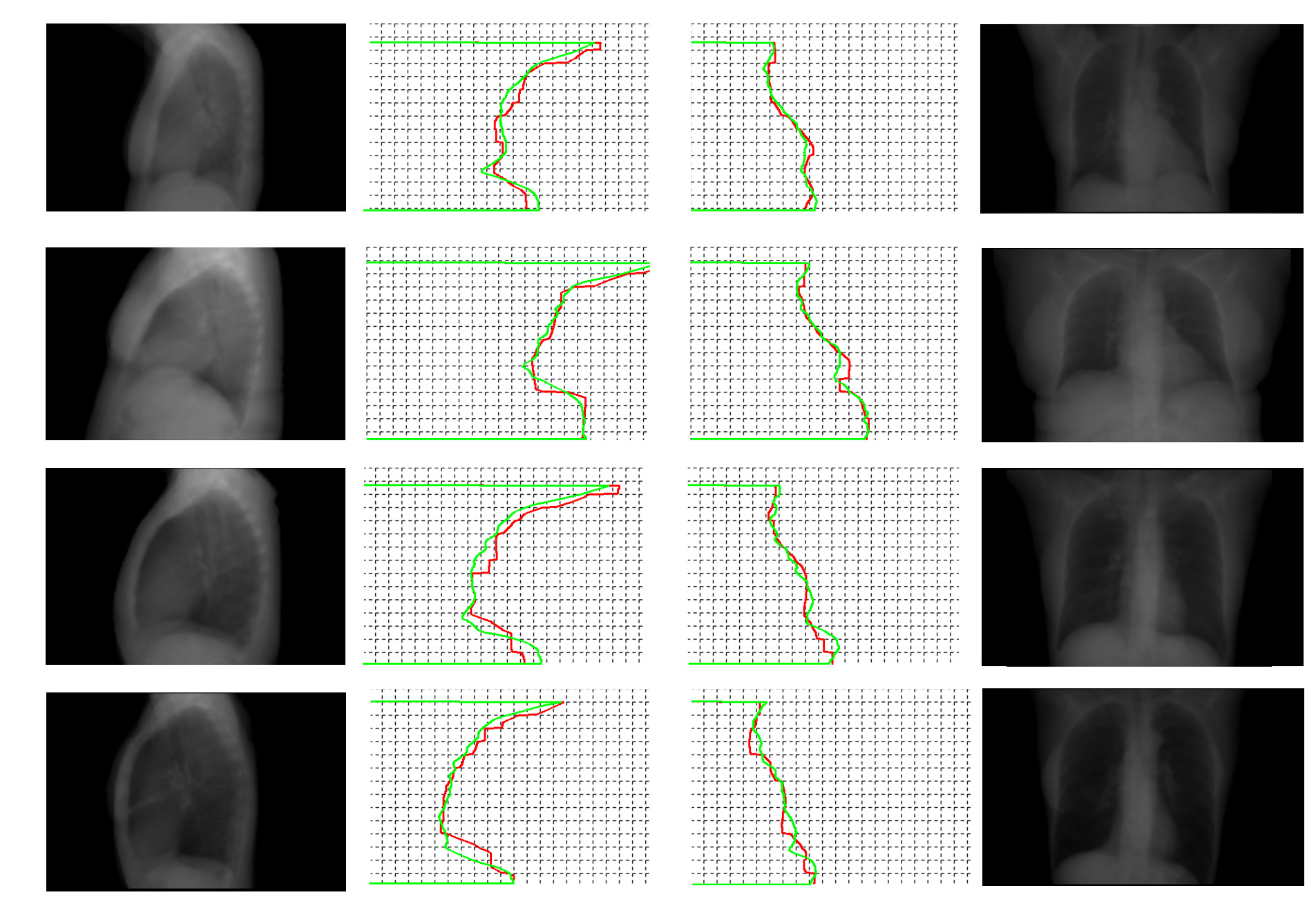
Figures 3 highlights the benefits of using real-time refinement. Overall, our approach shows best results with an update frequency of mm, with a mean lateral error of 15.93mm and a mean AP error of 10.40mm. Figure 4 presents a qualitative evaluation on patients with different body morphology.
Finally, we evaluated the clinical relevancy of our approach by computing the relative error as described in the International Electrotechnical Commission (IEC) standard IEC 62985:2019 on Methods for calculating size specific dose estimates (SSDE) for computed tomography [2]. The metric is defined as:
| (1) |
Where:
-
•
is the predicted water equivalent diameter
-
•
is the ground truth water equivalent diameter
-
•
is the position along the craniocaudal axis of the patient.
IEC standard states the median value of the set of along the craniocaudal axis (noted ) should be below 0.1. Our method achieved a mean lateral error of 0.0426 and a mean AP error of 0.0428, falling well within the acceptance criteria.
4 Conclusion
We presented a novel 3D camera based approach for automating CT lung cancer screening workflow without the need for a scout scan. Our approach effectively estimates start of scan, isocenter and Water Equivalent Diameter from depth images and meets the IEC acceptance criteria of relative WED error. While this approach can be used for other thorax scan protocols, it may not be applicable to trauma (e.g. with large lung resections) and inpatient settings, as the deviation in predicted and actual WED would likely be much higher. In future, we plan to establish the feasibility as well as the utility of this approach for other scan protocols and body regions. 111Disclaimer: The concepts and information presented in this paper are based on research results that are not commercially available. Future commercial availability cannot be guaranteed.
References
- [1] Huang, G., Liu, Z., Weinberger, K.Q.: Densely connected convolutional networks. CoRR (2016)
- [2] International.Electrotechnical.Commission: Iec 62985:2019 (2019)
- [3] Kalra, M.K., Maher, M.M., Toth, T.L., Schmidt, B., Westerman, B.L., Morgan, H.T., Saini, S.: Techniques and applications of automatic tube current modulation for CT. Radiology (Dec 2004)
- [4] Karanam, S., Li, R., Yang, F., Hu, W., Chen, T., Wu, Z.: Towards contactless patient positioning. IEEE Trans. Medical Imaging (2020)
- [5] Keller, M., Zuffi, S., Black, M.J., Pujades, S.: Osso: Obtaining skeletal shape from outside (2022)
- [6] Kingma, D.P., Ba, J.: Adam: A method for stochastic optimization. In: ICLR (2015)
- [7] Li, X., Chen, H., Qi, X., Dou, Q., Fu, C., Heng, P.: H-denseunet: Hybrid densely connected unet for liver and liver tumor segmentation from CT volumes. CoRR (2017)
- [8] of Physicists in Medicine, A.A.: Use of water equivalent diameter for calculating patient size and size-specific dose estimates (ssde) in ct (2014)
- [9] Mihailidis, D., Tsapaki, V., Tomara, P.: A simple manual method to estimate water-equivalent diameter for calculating size-specific dose estimate in chest computed tomography. The British Journal of Radiology (2021)
- [10] Park, J.J., Florence, P., Straub, J., Newcombe, R.A., Lovegrove, S.: Deepsdf: Learning continuous signed distance functions for shape representation. CoRR (2019)
- [11] Rajaraman, V., Ponnusamy, M., Halanaik, D.: Size specific dose estimate (ssde) for estimating patient dose from ct used in myocardial perfusion spect/ct. Asia Oceania Journal of Nuclear Medicine and Biology (2020)
- [12] Singh, V., Ma, K., Tamersoy, B., Chang, Y.J., Wimmer, A., O’Donnell, T., Chen, T.: Darwin: Deformable patient avatar representation with deep image network (2017)
- [13] Teixeira, B., Singh, V., Chen, T., Ma, K., Tamersoy, B., Wu, Y., Balashova, E., Comaniciu, D.: Generating synthetic x-ray images of a person from the surface geometry. In: IEEE Conference on Computer Vision and Pattern Recognition (CVPR) (2018)
- [14] Teixeira, B., Tamersoy, B., Singh, V.K., Kapoor, A.: Adaloss: Adaptive loss function for landmark localization. CoRR (2019)
- [15] Wu, Y., Singh, V., Teixeira, B., Ma, K., Tamersoy, B., Krauss, A., Chen, T.: Towards generating personalized volumetric phantom from patient’s surface geometry (2018)
- [16] Zeiler, M.D.: Adadelta: An adaptive learning rate method (2012)
- [17] Zhang, D., Liu, X., Duan, X., Bankier, A.A., Rong, J., Palmer, M.R.: Estimating patient water equivalent diameter from ct localizer images – a longitudinal and multi-institutional study of the stability of calibration parameters. Medical Physics (2020)
- [18] Zhang, D., Mihai, G., Barbaras, L.G., Brook, O.R., Palmer, M.R.: A new method for ct dose estimation by determining patient water equivalent diameter from localizer radiographs: Geometric transformation and calibration methods using readily available phantoms. Medical Physics (2018)