Task-Oriented Grasping with Point Cloud Representation of Objects
Abstract
In this paper, we study the problem of task-oriented grasp synthesis from partial point cloud data using an eye-in-hand camera configuration. In task-oriented grasp synthesis, a grasp has to be selected so that the object is not lost during manipulation, and it is also ensured that adequate force/moment can be applied to perform the task. We formalize the notion of a gross manipulation task as a constant screw motion (or a sequence of constant screw motions) to be applied to the object after grasping. Using this notion of task, and a corresponding grasp quality metric developed in our prior work, we use a neural network to approximate a function for predicting the grasp quality metric on a cuboid shape. We show that by using a bounding box obtained from the partial point cloud of an object, and the grasp quality metric mentioned above, we can generate a good grasping region on the bounding box that can be used to compute an antipodal grasp on the actual object. Our algorithm does not use any manually labeled data or grasping simulator, thus making it very efficient to implement and integrate with screw linear interpolation-based motion planners. We present simulation as well as experimental results that show the effectiveness of our approach. Website: https://irsl-sbu.github.io/Task-Oriented-Grasping-from-Point-Cloud-Representation/
I Introduction
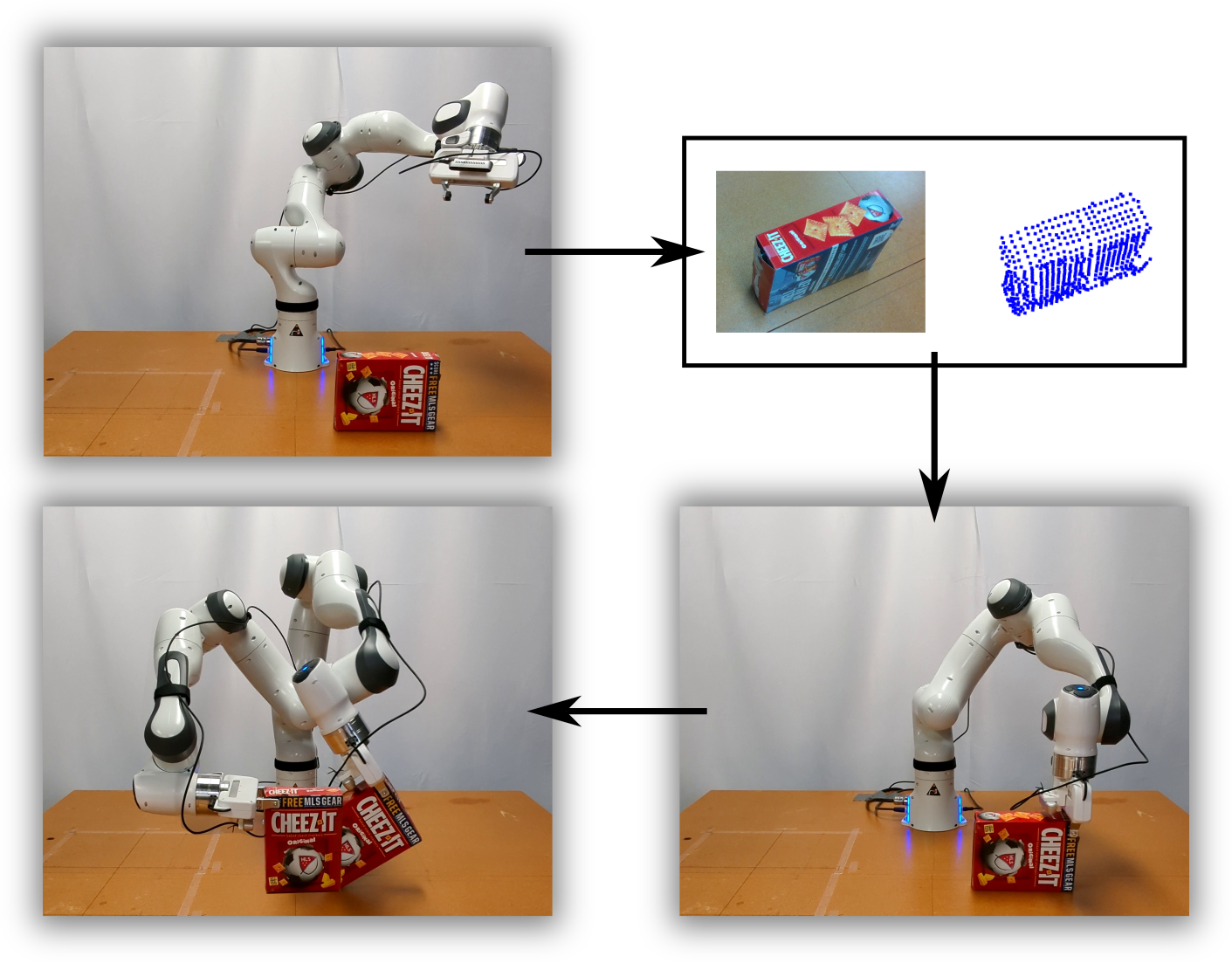
Grasp synthesis, in particular, sensor driven grasp synthesis is a fundamental problem in robotic manipulation. The extant literature on grasp synthesis has predominantly focused on pick and place tasks where the goal is to synthesize a grasp such that the grasp is not lost during movement (i.e., force closure conditions are satisfied). However, pick and place is just one type of manipulation task. In general, we grasp objects to give them a motion or apply a force (and/or moment) along (about) an axis. Figure 1 shows an example task of pivoting an object to give it a motion so as to set it upright. Other examples include grasping a screw driver to use it for fastening/unfastening a screw, grasping a spatula to use it, grasping a box of sugar to pour from it. Thus, task-oriented grasping is a key capability for robots to have to expand their usage beyond pick-and-place tasks. Furthermore, for a robot to operate in environments that are not specifically engineered for it, it has to sense the objects to be grasped and may not have a priori knowledge about the geometry of the objects (i.e., CAD models of the objects may not be available). Therefore, the goal of this paper is to develop an algorithm for task-oriented grasp synthesis with partial point cloud information about the objects.
Extant literature on sensor-based task-oriented grasp synthesis has focused on affordance-based grasping [1, 2], where human intuition about good regions to grasp for a task label is used to create datasets, and deep learning-based techniques are used to generate a grasp. However, the motion (or force/moments) to be applied to the object after grasping, which is also key for selecting a grasp region for many tasks, is usually not considered. For example, for the pivoting task shown in Figure 1, the region where the object should be grasped depends on the axis of pivot after grasping. Even if multiple grasps are provided as examples, the suitability of the grasp depends on the pivoting axis, and good grasps for one pivoting axis is a bad grasp for another axis. Similarly, in tasks like pouring from a symmetric object, the region of grasping depends on the axis about which the object should be rotated for pouring.
Therefore, in this paper, we focus on using motion to formalize the notion of task and present an algorithm for grasp synthesis to generate a desired motion. Following [3], we define a task as a unit screw about which the robot should generate a desired motion after grasping. More generally, we can think of a task as a sequence of unit screws about which the fingers/manipulators need to generate a desired motion after grasping. Although there are several formalizations of a task in the literature on computing metrics for task-oriented grasping [4, 5, 6, 7, 8], we use the screw geometry-based approach, as it allows us to directly connect our grasp planning to motion planning after the grasp [9, 10].
Given the gripper contact locations, and a task specified by a unit screw, one can evaluate the suitability of the locations for performing the task by computing a grasp quality metric using a convex optimization problem, namely a second order cone program [3]. However, solving the inverse problem of computing the contact locations given the task is much more challenging, even with the knowledge of the object geometry, since technically the problem becomes a non-convex optimization problem [11]. Furthermore, the potential presence of environmental contacts during manipulation, as well as partial knowledge of the object geometry, say, in the form of a point cloud, makes the problem more challenging. Therefore, more precisely, we have to solve the following problem: Given a partial point cloud representation of an object and a task defined by a unit screw, compute an antipodal grasp for manipulating the object, where manipulation may also require environmental contact with the object.
We present a novel grasp synthesis algorithm that uses a bounding box approximation of an object to generate grasps to provide a motion to the object after grasping. We assume that the object is being sensed with a RGBD camera, from which the partial point cloud is extracted. A key step in our approach is to learn a function that takes in a task screw and contact locations as input, and outputs a metric denoting the suitability of the contacts for manipulating a cuboid shape. We show that by using this function on the simplest possible geometric representation of the partial point cloud, namely, a bounding box, we can generate a good grasping region on the actual object. Experimental results are provided to validate our approach and show that it can be combined with a motion planner [9, 10] to generate a grasp for performing tasks like pouring and pivoting on different objects. Note that in pivoting there are contacts of the object with the environment apart from the gripper object contact, while in pouring there is no object environment contact. Our method can generate grasps for both of these categories of manipulation tasks. The neural network we learn uses data generated from the grasping force optimization algorithm [3] on cuboids. Therefore, we do not need CAD models of objects or example grasps from a dataset to generate the grasps.
For example, to pour from a cup, one should not hold the inside surface of the cup is The notion of task-oriented or task-relevant grasping has been discussed in the extant literature in the context of developing grasp quality metrics [4, 5, 6, 7, 8] as well as approaches for sensor-based grasp synthesis (e.g., [1, 2]). Whereas the grasp quality metric literature formalize the notion of task-relevance, the literature on dataset driven task-oriented grasp computation do not use these formal notions. The notion of task-relevance is based on (usually) human provided labels in datasets associating a degree-of-freedom (DOF) gripper pose or contact regions on objects to a task label (verb). While such labels or task affordances can be useful, especially when the object has a region meant to hold it, they do not capture the actual motion to be performed after the task. For example for the pivoting task shown in Figure 1, the region where the object should be grasped depends on the axis of pivot after grasping. Even if multiple grasps are provided as examples, the suitability of the grasp depends on the pivoting axis, and good grasps for one pivoting axis is a bad grasp for another axis. Similarly, in tasks like pouring from a symmetric object, where the grasp should be depends on the axis about which the object should be rotated for pouring. Thus, in the extant literature on task-oriented grasping, most work (exceptions include ) do not consider the motion to be performed after grasping, which is key for selecting a proper grasp. Therefore, in this paper, following [3], we define a task as a unit screw about which the robot should generate a desired motion after grasping. More generally, we can think of a task as a sequence of unit screws about which the fingers/manipulators need to generate a desired motion after grasping.
Much of the sensor-based task-oriented grasp synthesis literature has focused on affordance-based grasping, where human intuition about good regions to grasp for a task label is used to create datasets and deep learning based techniques are used to generate a grasp.
-
•
A well defined mathematical notion of a task in terms of the task screw, , that allows us to connect our grasp planning algorithm to a motion planning algorithm seamlessly.
-
•
The task screw, , is part of the input to our neural network for approximating the ideal grasping region, , for the bounding box of a partial point cloud . We then use to compute , that is the ideal grasping region corresponding to the partial point cloud of the object, .
-
•
The same task screw, , which is used for computing the ideal grasping region, , is also used for motion planning to perform tasks and vice-versa. This allows us to establish a natural link between task-based grasping and motion planning. To the best our knowledge, we are the only ones to do so using partial point clouds obtained from a ’eye-in-hand’ perception system and with a neural network at the heart of our algorithm.
-
•
This makes our proposed approach independent of object category and rather more inherently related to the motion imparted to an object about the task screw, . We reinforce this claim by performing real-world experiments using a robot for objects belonging to different categories. However, the underlying objective of the tasks is the same i.e. imparting a constant screw motion to the object about the associated task screw .
-
•
Since we assume that a bounding box can be used as the simplest geometrical representation of a partial point cloud for grasping, we first explain the process of computing the ideal grasping region for a cuboid where the objective is to generate the desired motion about the task screw, . We use our task-dependent grasp metric formulated as a SOCP in our previous work [3] to compute the ideal grasping region for pivoting a cuboid in simulation for the same. This serves as the basis for our data generation process elevating the need for using CAD models of category specific objects making sim-to-real transfer easier.
-
•
Our technique also allows us to perform grasp synthesis for tasks like pivoting objects using the environment where it is necessary to leverage the object-environment contact and compute the object-robot grasps accordingly.
II Related Work
Sensor driven grasp synthesis has been studied primarily for pick and place tasks, although recent efforts have also focused on task-oriented or task-relevant grasping. Since this paper is about task-oriented grasping we will limit our discussion to the task-oriented grasping literature. A more detailed discussion on grasp synthesis can be found in the excellent review article [12].
There are two key aspects to task-oriented or task-relevant grasp synthesis, namely, (a) the knowledge of the regions of an object that can/cannot be grasped for performing a particular task, and (b) the motion (or forces/moments) to be applied to the object to accomplish the task. As stated before, the sensor-driven grasp synthesis literature [13, 14, 15, 16, 17, 18] primarily focuses on the aspect (a) above. The notion of task-relevance is based on (usually) human provided labels in datasets [19, 20] associating a degree-of-freedom (DOF) gripper pose or contact regions on objects to a task label (verb). Such labels or task affordances are sufficient for some tasks like handover, or for moving objects that has a handle to hold it. However, there are other tasks like pivoting, pouring, turning a handle, etc., where the grasp selection also depends on the motion to be performed after grasping. Our paper focuses on these type of tasks where the motion to be performed after grasping is key to the successful accomplishment of the task.
In [18], the authors present a deep-learning based algorithm for grasp selection as well as a policy for motion after the grasp selection for two types of tasks, namely, hammering and sweeping. The focus is on using the same object for these two types of tasks and it was assumed that the sensor data is a depth image data from a fixed overhead camera. This approach does not easily generalize to our scenarios where we have partial point cloud data from a eye-in-a-hand configuration. Further generalization to tasks like pivoting where the objects can be in contact with the ground during manipulation after grasping is also not clear. As such there are no approaches or datasets for task-oriented grasping that has data for performing tasks where there may be contacts other than finger object contact which constrains the motion during manipulation and has to be taken into consideration for grasp synthesis.
In contrast, we take an alternate route for sensor-driven grasp synthesis, where we first formalize the notion of a task using the screw geometry of motion. Further, we use task-oriented grasp metrics to learn a function to evaluate the suitability of an antipodal grasping region for a given task specified by a unit screw. Grasp metrics like the Ferrari-Canny metric [21] has been used for pick-and-place tasks [22, 23, 24, 25, 26, 27, 28] and our idea of using the task-oriented grasp metric for grasp synthesis was inspired from these works.
Metrics to Evaluate Grasp Quality: Grasp quality metrics are used during grasp synthesis to evaluate the possible grasps. Grasp metrics can be broadly categorized into task-independent grasp metrics [21, roa2015grasp, kirkpatrick1992quantitative] which do not take into consideration any information pertaining to the task or task-dependent grasp metrics [roa2015grasp] which use a well defined notion of a task [4, 5, 6, 7, 8]. Most commonly used grasp metrics consider the wrenches applied by the end-effector on the object while evaluating grasps. These wrenches are characterized in terms of the Grasp Wrench Space (GWS), which is the set of all wrenches, including contact wrenches acting on the object [roa2015grasp, 21, 4]. Task-dependent grasp metrics have defined a task in terms of a unique set of wrenches, acting on the object that need to resisted, known as the Task Wrench Space (TWS) [4, 5]. The task associated with a task-dependent metric has been defined, more recently, as a unit wrench acting in a particular direction in the TWS [6, 7, krug2018evaluating]. As studied in [roa2015grasp, krug2018evaluating, lin2016task], it is diffcult to compute the TWS or GWS. In our previous work, we defined a task-dependent grasp metric as the maximum magnitude of wrench that can be exerted along a screw axis [3]. The grasp quality metrics described above are more commonly known as physics-based metrics. Rubert et. al analyzed 7 different grasp quality metrics, along with the Ferrari & Canny metric, for predicting whether a grasp can be successful [rubert2017relevance]. Task-independent grasp metrics like the Ferrari & Canny metric [21] have been used widely in deep learning-based approaches for grasp synthesis [12], more recently in [24]. To the best of our knowledge, we have not come across deep learning-based techniques for grasp synthesis that use task-dependent grasp metrics for evaluating grasp ‘quality’.
Task-Oriented Grasping Techniques: Task-oriented grasping is inherently dependent on the definition of a task. Based on the definition of a task, grasps can be evaluated for their task relevance as well as stability. Recent deep learning-based approaches for task-oriented grasping do not use a mathematically defined notion of a task. Some works use semantic labels, like “pouring” or “handover”, for tasks corresponding to suitable grasping regions on the object. They aim at modelling the relationship between the semantic label of a task, object and a grasp using the notion of affordance [13, 14, 15, 16, 17, 18]. Another approach is to generate a number of predefined grasps on objects corresponding to a particular task label, thereby establishing task relevance [murali2020same]. Instead of using semantic task labels, the authors in [1, 2] focus on computing suitable grasping regions on category specific objects such that their primary functionality is not affected. Wen et. al [2] propose a method which transfers task-relevant grasps to novel object instances of three categories namely nuts, screws and HMNs. Their proposed method computes grasps such that the functionality of the object for a placement task is not affected. For example, grasping a screw at the thread region would not be suitable if our goal is to place it in a hole. A similar category-based approach has been adopted by Kokic et. al in [1] for computing grasps on bottles, spoons and knives using human activity datasets.
Existing methods try to find the right trade-off between a grasp’s stability and its task relevance [1]. Please note that task relevance of a grasp depends on the definition of a task. The ability of a grasp to resist external wrenches acting on the object is considered as a good measure of grasp stability [Murray1994, bicchi2000robotic]. Without a mathematical notion for a task, which considers the motion of the object and/or the wrenches required to generate the motion, it is difficult to couple a grasp’s task relevance with its stability. Therefore, separate techniques are used to analyze a grasp’s stability and its task relevance. Wen et. al [2] use the Grasping Q Net for predicting grasp quality based on its stability. Category specific hand-object contact heatmaps, generated in simulation, are used along with the predicted stability score to compute the task-relevance of grasps on novel object instances. Kokic et. al use their TOG-S network [antonova2018global] to predict grasp stability and the TOG-T network [1] for predicting the task relevance of a grasp for objects of a specific category.
In this work, we define a task as a unit screw about which the end-effector needs to apply a wrench in order to generate the desired motion. Using our task-dependent grasp metric [3], we can compute the magnitude of the wrench associated with
III Task-Oriented Grasping
In this section we formalize the notion of a task and present our problem formulation of sensor-driven task-oriented grasping. Our formalization is based on the fact that, in the analysis of rigid body motion, a screw is the underlying geometric entity for both twists (i.e., linear and angular velocity pairs) as well as wrenches (i.e., force/moment pairs).
We define a task as a unit screw about (along) which a desired motion has to be generated for an object by using a robotic hand that has to apply a wrench to generate the desired motion. Henceforth, we will refer to this unit screw as the task screw, , which is a line in space. We represent using its Plucker coordinates , where, is a unit vector along and is the moment with being any point on . We assume that the gripper to be used is a parallel jaw gripper and thus the grasp is antipodal.
Problem Statement: Given a point cloud representation, , of a single object and a task screw, , in terms of its Plucker coordinates , compute a grasping region for an antipodal grasp, such that the grippers after grasping the object can apply the desired motion on the object specified by the task screw .
Note that both and are expressed with respect to a fixed object reference, . The ideal grasping region, , can be used to compute a set of -DOF end-effector poses, , such that upon closing the parallel jaw gripper at any one of the poses we would be able to apply the necessary contact wrenches thereby imparting the desired motion on the object and accomplishing the task.
III-A Definition of Task and Task-Dependent Grasp Metric:
We define a task as a unit screw about which the end-effector/manipulator has to apply a wrench in order to generate the desired motion. Explain with examples and remove it from the next section?. Henceforth, we will refer to this screw as the task screw, , and define it in terms of its Plucker coordinates , which are a unit vector, , along and a moment, where is any point on . The task screw, , can be used to characterize a constant screw motion or wrench along it. This is in accordance with Poinsot’s theorem which states that every wrench applied to a rigid body is equivalent to a force applied along a fixed screw axis and a torque about the same axis [Murray1994]. We want to compute a wrench , equivalent to a wrench along . It is important to note that will be generated/applied by the grasp on the object and it can be mathematically represented as
| (1) |
where is a force along the axis and is the torque about . The screw pitch, , can be computed by . The term , where is any point on , represents the moment of the force about the origin of the reference frame. Using the definition of a task as a constant screw motion or wrench along a axis, , with a given pitch , we define our task-dependent grasp metric as the maximum magnitude of a wrench that a grasp can generate along .
III-B SOCP-based Formulation for Task-Dependent Grasp Metric:
The task-dependent grasp metric, , can be computed using the following second order cone program (SOCP)
| (2) | ||||||
| subject to | ||||||
where when and when . Please note that the optimization variables in the above formulation are , and . The task screw is assumed to be known for a specific task. For a detailed description of (2) we urge the readers to refer to [3].
Our objective is to perform task-oriented grasping using point cloud representation of objects. We aim to synthesize grasps that can be used to execute tasks, directly from point cloud data. However, there are some issues with implementing the optimization formulation described in (2) directly for grasp synthesis on point cloud data. Firstly, our optimization formulation is used to evaluate grasps for executing a specified task. Given a grasp i.e. the contact locations and a task specified by , our metric determines the quality of the grasp for performing the task. The contact locations need to be known beforehand in order effectively compute the value of the metric, . Secondly, the formulation implicitly assumes that the complete geometry of the object being grasped is known. A key challenge in grasping using sensor data is that it is inherently noisy and incomplete due to occlusion. Since sensor data is noisy and incomplete leading to uncertain geometric model of an object, a question that arises is: What is the simplest geometric model of an object that can be used for grasp planning? Our answer is a bounding box.
IV Problem Statement
Given a point cloud representation, , of a single object and a task screw, , in terms of its Plucker coordinates , compute a grasping region, such that the grippers can apply adequate wrench to impart a desired motion on the object. Both and are expressed with respect to a fixed object reference, . In this work we only consider tasks where the grasp needs to generate a moment about the task screw i.e. and . For example, tasks like pivoting cuboidal objects require a moment to be applied by the end-effector of the robot about some task screw in order to generate the desired motion. The ideal grasping region, , can be used to compute a set of 6-DOF end-effector poses, , such that upon closing the parallel jaw gripper at any one of the poses we would be able to apply the necessary contact wrenches thereby imparting the desired motion on the object and accomplishing the task.
V Task Oriented Grasping From Point Clouds
Our overall grasp computation strategy can be divided into the following steps: (1) Compute a bounding box of the partial point cloud data, (2) Evaluate the grasp metric on the bounding box, , to (implicitly) find the ideal grasping region on , (3) Convert to an ideal grasping region on the object surface. The computation of the bounding box of a point cloud data is a classical problem in computer vision and we use off-the-shelf algorithms for step (please see the results section for more details). The steps , and are described below and forms the bulk of the technical contribution of this paper.
V-A Computing Ideal Grasping Region on Cuboids
Since the bounding box of an object is a cuboid, we first present a solution for computing antipodal grasps on a cuboid object. To compute an antipodal grasp on a cuboid to give a constant screw motion about/along a given screw axis, a naive strategy is to discretize the faces of the cuboids, compute the grasp metric for antipodal grasps using the formulation in our previous work [3], and then select the grasp with the maximum value. However, the grasp metric computation for each antipodal grasp involves solution of a second order cone program (SOCP). Thus, the time taken for performing this computation would not allow real-time grasp computation. Therefore, we train a neural network that allows for a fast approximation of the grasp metric value for a given antipodal contact location and task screw.
V-A1 Approximating the Grasp Quality Metric
The neural network to approximate the grasp quality metric approximates the target function : . Each element, , is of the form: , where the vectors, and , are a pair of antipodal contact locations sampled from the two opposite faces, and , of the cuboid, . The last two elements are the Plucker coordinates of the task screw, . The output of the neural network, , is the value of the normalized task-dependent grasp metric, . The output space can be defined as . All parameters of the input vector, , are expressed with respect to . A key aspect of learning the function is generating the training data, which we discuss next.
V-A2 Training Data Generation
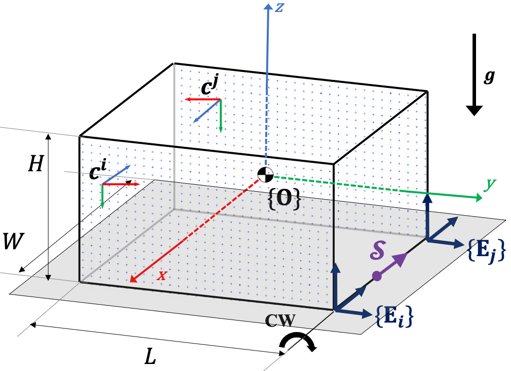
To generate training data, we select the task of pivoting a cuboid about one of its edges, in simulation, as shown in Fig. 3(a). The objective is to generate a constant screw motion about the task screw, , which lies along the pivoting edge. A key reason for selecting the pivoting task for data generation is that it includes object-environment contact, and by setting the environmental contact force to zero, we can consider situations with no object-environment contact. Each pair of antipodal contact locations, and along with the object-environment contacts at and and the task screw, , form one instance of the optimization formulation in [3]. Upon solving the formulation for each grasp, (, ), we have an associated metric value, , which denotes the maximum magnitude of moment that can be generated about .
The parameters that affect the value of , in addition to the locations of the antipodal and object-environment contacts, are the weight of the object, the location of the task screw, , and the contact friction. The weight of the object is kept constant for all instances because varying the weight only changes the magnitude of and not the actual order of (, ) imposed by . For the friction coefficient at and , we randomly sample values from a normal distribution, and compute by solving the optimization formulation in [3]. The final value of associated with (, ) is the average of these values. For each grasp, the coefficient of friction is kept the same for both object-robot contacts, i.e. . The coefficient of friction at both the object-environment contacts is kept constant, .
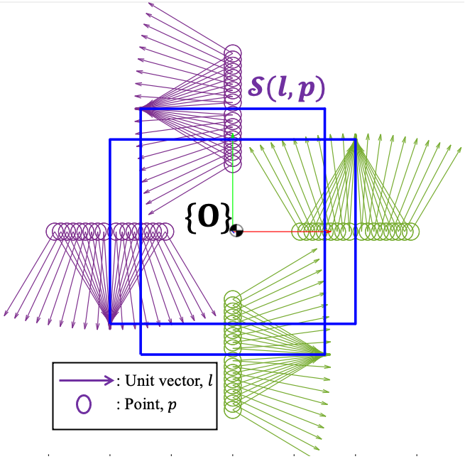
To capture the variation in the task screw, , and its effect on the value of , we vary the length, , of one of the two faces, or , by a positive scalar . This allows us to generate different cuboids where the length, , of one face is different from the length, , of its parallel face. The variation in the unit vector, , and the point, , corresponding to the task screw, , in our dataset is shown Fig.3. Each unit vector, , and point, , correspond to the pivoting edge of a cuboid where the lengths of the parallel faces have been varied and lies at the center of the pivoting edge. In our dataset we have a total such cuboids. We sample antipodal contacts, and along min, while keeping the width and height constant for all the cuboids. The metric values are normalized for each cuboid separately before being used for training. To summarize, for each cuboid, we sample along the faces perpendicular to the task screw, , and solve multiple instances of the optimization formulation [3], thereby computing the normalized metric value, , associated with each datapoint, . For generating the dataset the optimization formulation has been implemented using the CVX toolbox[29] in MATLAB with the SDPT3 solver.
V-A3 Feature Vector Design
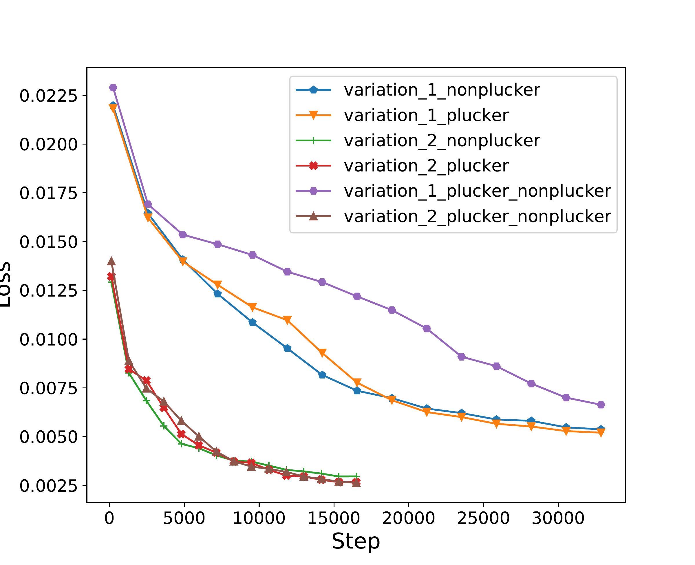
We will now discuss the different variations of feature vector input and datapoints used to train our neural network architecture. Using different representations of the task screw, , along with , we generate different input feature vectors with Plucker coordinates, , non-Plucker coordinates, and a combination of both, . Note that the and feature vectors are dimensional and the is dimensional. The antipodal contacts, , and the location of the task screw, , influence the value of the task-dependent grasp metric . Therefore, as additional features, we include the magnitude of the moment arms between -, - and -. The moment arms along with the antipodal contact locations and the task screw representation form our fourth and final input feature vector . We would like to highlight the fact that there is no change in the normalized metric values, , for the different variations of the input feature vector, as it is calculated using our optimization formulation [3]. In terms of the number of datapoints used for training, we use two variations, as shown in Fig. 3. The first variation (shown in green) consists of 46,512 datapoints from 72 cuboids. For the second variation, we include additional datapoints (shown in purple) bringing the total to 93,043 datapoints and 144 cuboids.
V-A4 Neural Network Ablation Study
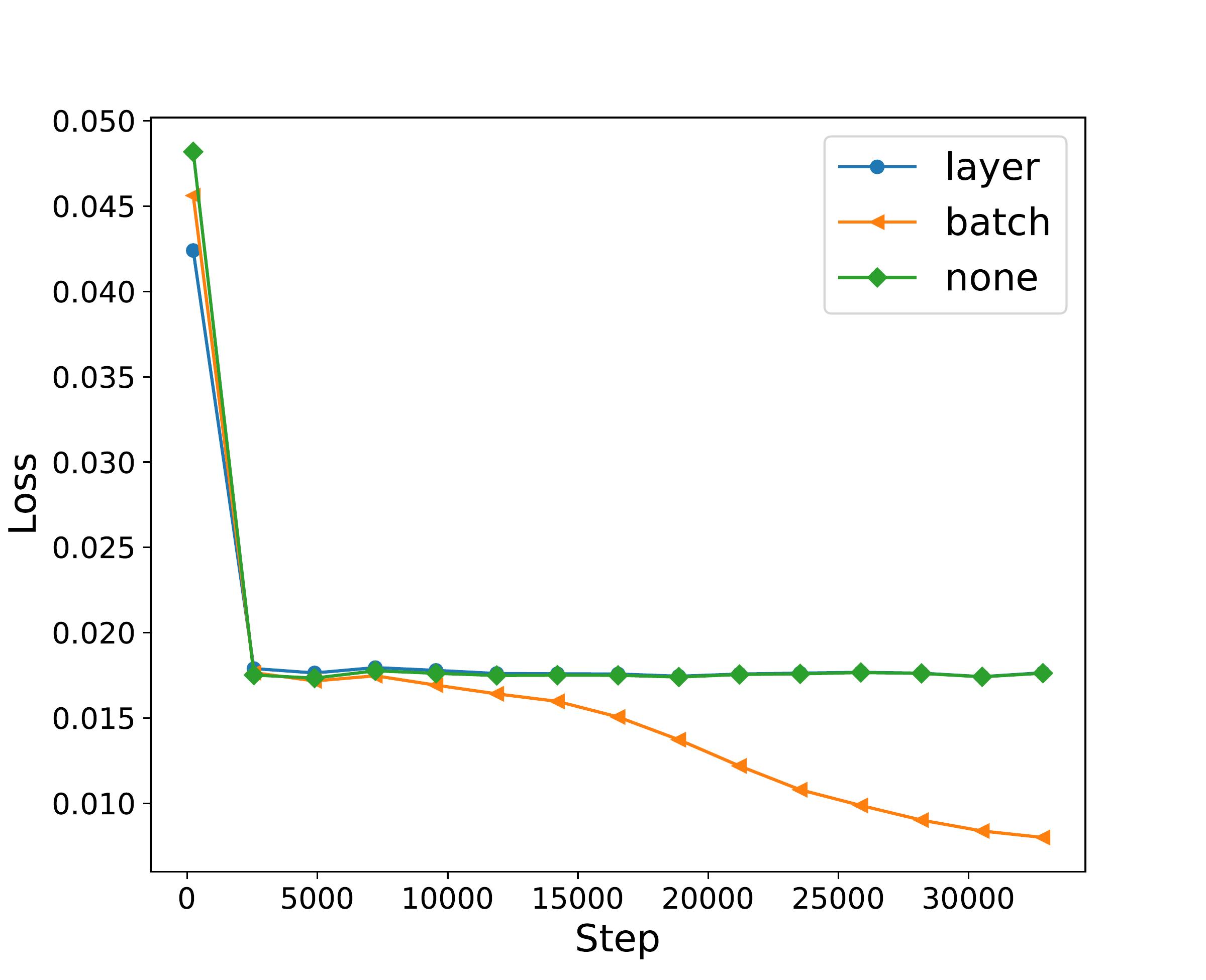
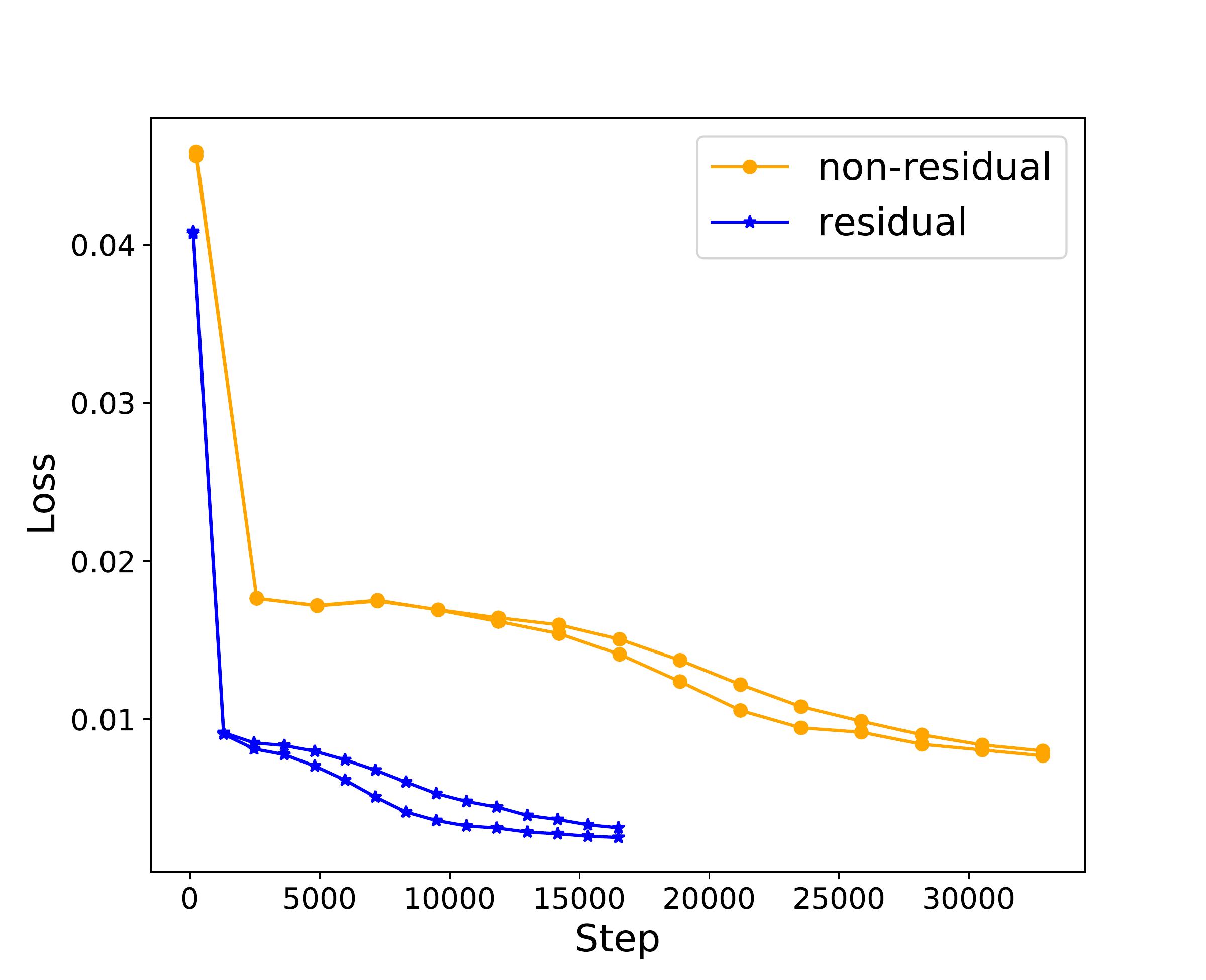
To approximate our task-dependent grasp metric, we use a fully connected Multilayer Perceptron (MLP) implemented using PyTorch. We experimented with all the feature vectors described above as input and obtained the lowest training loss using an input feature vector with Plucker coordinates when trained with the first variation of our data. This is shown in the leftmost graph of Fig. 2. Thus, for our input, we choose a feature vector using Plucker coordinates. Increasing the number of hidden layers in the MLP beyond eight layers does not significantly reduce training loss. We also observed that the ReLU activation function significantly reduces the training loss. Additionally, we experimented with the usage of skip-connections. Skip connections were introduced by [30] for convolutional neural networks (CNN) to gain accuracy with increasing depth. Our tests have shown that the addition of skip-connections also drastically lowers the training loss, and this is shown in the rightmost graph in Fig.2. To determine the type of normalization to use for our network, we experimented with BatchNorm [31] and LayerNorm [32]. We found that BatchNorm yielded significantly lower training loss compared to layer normalization or when normalization was not applied. This comparison is shown in the middle graph in Fig. 2. Based on the observations made above, our MLP comprises of eight hidden layers that uses the ReLU activation function, normalized by BatchNorm and with added skip-connections. Our network is trained using the Stochastic Gradient Descent algorithm and the Mean Squared Error (MSE) loss function on a desktop with NVIDIA RTX 3060. We set our learning rate to and train our model for epochs using a batch size of .
Computation of grasp metric on bounding box: We use the neural network above, which is trained to approximate the grasp quality metric, with the bounding box of the partial point cloud of the object to form an implicit representation of the ideal grasping region . Algorithm 1, lines - explains this. In line of Algorithm 1 we generate a grid on two parallel faces, and , of the bounding box and select antipodal contact locations, from the same. The faces are selected according to the dimensions of the bounding box and maximum allowable width of the gripper opening, . The output of our neural network provides an order for each pair of antipodal contacts, , , based on their corresponding metric value , forming an implicit representation of the ideal grasping region corresponding to the bounding box, .
V-B Computing the Ideal Grasping Region on Objects
Our goal now is to use , to obtain an ordering of the actual points in that is described by lines - of Algorithm 1. The point cloud, , is projected on either of the two parallel faces, or , of the bounding box . Let us denote the point cloud projected on the face as . We create a grid, , along using the corresponding contacts as the vertices of each element. These elements are assigned a metric value , which is the average of the metric values corresponding to the contacts at the vertices of the element. Essentially, we have converted a vertex-based representation of approximated metric values along , to an element-based one. Next, we check which points of lie in a particular element of , and the metric value, , associated with that element is assigned to the points occupying it. Each point in and their corresponding metric value, , is projected back to its original location in . Using a threshold, , we extract the points with as explained in lines - of Algorithm 1. These points would correspond to the ideal grasping region . Thus, we now have a set of points, , where if the object is grasped then the manipulator would be able to generate the necessary moment about the task screw, .
V-C Computing -DOF End-Effector Poses
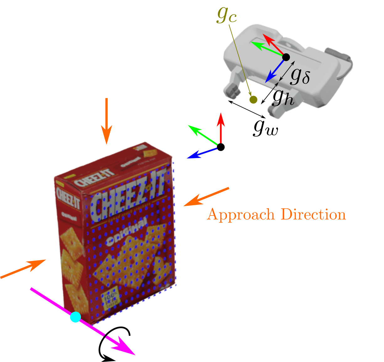
In order to provide the necessary screw motion to an object using a robotic manipulator, we need to compute a set of 6-DOF end-effector poses corresponding to the ideal grasping region, . We use 2 heuristic-based algorithms depending upon our choice of the object–end-effector contact locations, . The dimensions of the bounding box and the gripper width are used to we select two parallel faces and for approximating . The algorithm uses the elements of the grid generated along, or , where . Note that only the elements which are occupied by the points of the projected point cloud, are selected. The element centers are used as the contact locations, and their normals are unit vectors perpendicular to the faces and , pointing inwards. The grasp center, , which lies halfway along the line joining and , is computed using the dimensions of the bounding box . The algorithm randomly select a point, , as one of the contact location, . The orientation of its corresponding normal and dimensions of the bounding box are used to compute the location of the other antipodal contact, , along with the grasp center, . Out of the possible approach directions we select the ones which do not result in collisions between the object and the end-effector. This is done by checking the distance from the grasp center, , to the faces of the bounding box corresponding to the approach directions. The gripper geometry is then used to check the feasibility of grasping at from a particular direction as shown in Fig.4. As stated previously for the 2 algorithms, the end-effector orientation is fixed based on the approach direction as shown in Fig 4 (a).
VI Experimental Evaluation
We evaluate the performance of our proposed grasp synthesis approach using (a) simulated partial point clouds (b) data obtained from a RGBD camera and (c) real world experiments with a robot where the objective is to impart a constant screw motion to an object about an associated task screw, . To evaluate the quality of the grasps, we propose a metric which we call the final grasp evaluation (FGE) metric. Although, our training data has been generated using the task of pivoting an ideal cuboidal object, we show that the proposed neural network-based approach can be used to compute ideal grasping region for objects which are not necessarily cuboidal in shape. Thus, our approach is not limited to a particular category, like boxes or bottles, rather it is inherently related to the motion imparted to the object by generating a moment about a particular task screw . This key point influences our choice of tasks to be used for performing experiments using sensor data.
Final Grasp Evaluation (FGE): To evaluate the ideal grasping region, , computed using our neural network based approach, we devise a metric to compare it with the output from the algorithm to compute the optimal value of the task-oriented grasp metric in [3]. The goal is to check how well our computed regions match with the optimal grasping region that can be computed using [3], but is computationally expensive. The same point cloud and task screw is used for both computations by varying the step of the Algorithm 1. We refer to the ideal grasping region computed using [3] as and the one approximated using our neural network as . Since the metric value computed by our NN is scaled between and , whereas the output of [3] is not scaled, for comparison we need to put them on a common scale. We select the top antipodal contact locations from and top antipodal contact locations from such that . The optimization formulation is used again to evaluate these antipodal contact locations by computing their corresponding value of the task-dependent grasp metric, . Upon normalizing the values of for the contacts, we extract the maximum normalized value, , corresponding to the contact locations from our NN. Higher the value of , the closer the antipodal contact locations are to the optimal grasp.
VI-A Evaluating Grasp Synthesis with Simulated Data
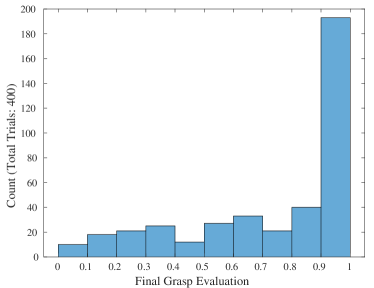
We consider a total of different objects in our experiments. The CAD and URDF models of the objects are sourced from [33, 34] and the PyBullet simulation environment is used to extract the partial point clouds. For each object we randomly select task screws different from the ones in our training data. Thus, we have a total of trials. For each trial, we compute the ideal grasping region using our neural network-based approach and evaluate it using our proposed FGE metric. We set and , for computing the FGE metric, .
Results and Discussion: Figure 5 shows our experimental results displayed as a histogram with the FGE metric as the -axis. As seen from the figure, was observed most number of times. This indicates the ability of our neural network-based approach to compute the ideal grasping region effectively as compared to our optimization formulation.
VI-B Evaluating Grasp Synthesis with Real Point Clouds
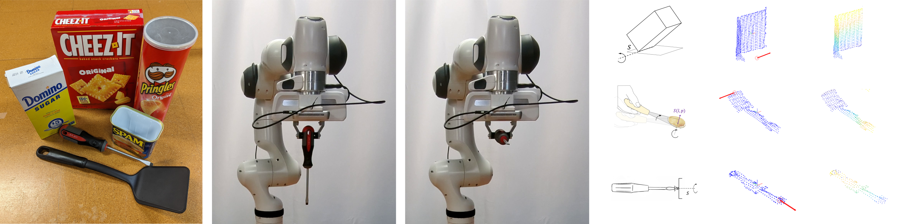
Here, we evaluate our approach for computing the ideal grasping region, , on actual sensor data. The data is collected using an Intel Realsense D415 camera mounted on a Franka Emika Panda. Point cloud segmentation is performed using pretrained DeepLab [35] on RGB images and the corresponding semantic segmentation is used along with the depth channel to get the points. We use off-the-shelf algorithms for point cloud processing, normal computation, and computing the bounding box. Vertices of the bounding box are used to compute a fixed object reference frame , and the bounding box, , the object point cloud, and the task screw, , are all expressed with respect to . Thus our results do not depend on the absolute pose of the objects in the world frame. The objects used for this experiment are shown in Figure 6(left). Each object is placed at different poses, and for each pose, different camera poses are used giving us a total of partial point clouds per object. Note that all the objects associated with the tasks above are novel to our grasp synthesis algorithm. However, they are known to the semantic segmentation algorithm of our perception system.
| Object (Task) | Trials | Mean FGE |
|---|---|---|
| Screwdriver (Screwing Motion) | 9 | 0.931 |
| Spatula (Pivoting) | 9 | 0.928 |
| CheezIt (Pivoting) | 9 | 0.99 |
| Domino Sugar (Pivoting) | 9 | 0.784 |
| Pringles (Pouring) | 9 | 0.967 |
| Spam Tuna (Pouring) | 9 | 0.835 |
We choose three different tasks, namely, screwing motion, pivoting, and pouring as shown in Table I. For each task, the task screw, , is specified. For pivoting, we know the specific edge about which to pivot the CheezIt box and for the screwdriver we know the motion is about an axis along the shank. However, for any given object pose, it is difficult to know the exact location of the task screw , and in our implementation we use the bounding box to approximate its location i.e. the point, , and its direction, . For tasks like pouring, it is difficult to define the task-related constraints imposed on the motion. We leverage an algorithm proposed in [9] and extract the task screw from a single kinesthetic demonstration of pouring. Recall that computing requires us to solve multiple instances of the optimization formulation [3]. To accurately reflect the conditions of the task, we need to take into consideration any object-environment contacts if necessary. This is being done for the task of pivoting with all the objects. In this set of experiments, for each trial we set and while computing FGE.
Results and Discussion: The results of the experiments are displayed in table I. The first column specifies the object and its associated task and the second column shows the number of trials conducted for each object. The third column shows the mean value of the final grasp evaluation, , for each of the 9 trials. The mean values of FGE for all the objects are closer to which is desirable. This shows that we can sample antipodal contact locations, , from the ideal grasping region that can generate the desired magnitude of moment about the task screw even for partial point clouds obtained from a RGBD camera.
VI-C Task Oriented Grasping with a Robot
We evaluate our method using three different tasks (1) operating a screwdriver (2) pivoting a box about its edge and (3) pouring using the same hardware setup as above, where the robot grasps the objects and performs the motion (please see companion video).
| Object (Task) | Trials | Successful | Mean FGE |
|---|---|---|---|
| Pringles (Pouring) | 5 | 5 | 0.91 |
| CheezIt (Pivoting) | 8 | 6 | 0.99 |
| Domino Sugar (Pivoting) | 8 | 7 | 0.96 |
| Spam Tuna (Pouring) | 6 | 5 | 0.892 |
| Screwdriver | 15 | 5 | 0.891 |
Similar to the previous set of experiments, we assume that the task screws are known beforehand. After computing the ideal grasping region, , we use the algorithm in Section V-C to compute the corresponding set of end-effector poses, , and randomly select one end-effector pose for grasping. For the pivoting and screwing motion, apart from computing the ideal grasping region, , their corresponding task screw to compute the final pose using Screw linear interpolation (ScLERP) [36]. A ScLERP-based motion planner [10] is then used to generate a motion plan from the initial end-effector pose. For the task of pouring, the sequence of constant screw segments extracted from a kinesthetic demonstration is used along with the ScLERP-based motion planner to generate motion plans [9]. Note that we use position control for executing the motion and set a fixed upper limit for the maximum force that can be applied by the grippers. The grasp computation takes approximately seconds on an Intel processor with GB RAM and all the experiments are done with real-time grasp computation and planning.
Results and Discussion: The results are shown in Table II. The column shows the total number of trials conducted for each task and the column shows the number of successful trials. The last column shows the mean value of the final grasp evaluation metric for all the trials. The mean value of FGE is close to indicating that upon sampling contact locations from the ideal grasping region, , we can get good grasps. But this does not necessarily translate to successful task execution as we use a different criteria for evaluating the success for each task. For example, in the case of a screwdriver, keeping the orientation constant throughout the motion after grasping, is desirable. Although the screwdriver was grasped and picked up for every trial, its orientation was not maintained at all times (see Figure 6, 2nd and 3rd panels from left). We classified a trial as failure if the screwdriver was not horizontal after picking up. The key reason for the failures is that the screwdriver has a slightly curved end and we are not controlling the gripper force directly, which makes it difficult for the parallel jaw grippers to maintain the contact force to prevent the rotational slip.
For pivoting, in trials (out of ), the robot was able to successfully pivot the objects The failures were due to error in computing the task screw from the partial point cloud data thereby introducing inaccuracies in the motion plan. This causes the box to slip at the object-environment contact or it is pushed against the surface triggering the robot’s collision detection mechanism. For pouring, there was successful trials and failures. The one failure was due to failure in grasp due to slipping.
VII Conclusion and Future Work:
In this paper we present a novel grasp synthesis approach for task-oriented grasping from partial point cloud data of objects, where we want to give a motion to the objects after grasping. Many high level tasks like pivoting, pouring, and turning a handle are tasks where the goal of manipulation after grasping is to give a particular motion to the object. Our approach of exploiting the screw geometry of motion to define a task allows us to integrate the grasp synthesis algorithm with a class of ScLERP based motion planning approaches [10]. Furthermore, since we use a very simple geometric representation of the partial point cloud as a cuboid to compute the grasping region on the object, we do not need any prior knowledge about the objects to generate the grasps. We present both simulation and experimental results to show the validity of our approach for realistic manipulation tasks with real sensor data.
Our approach is complementary to the approaches of task-oriented grasping where human knowledge is used to label the good grasping regions. In the future we plan to combine labels on good grasping regions along with the bounding boxes on partial point clouds of the objects to incorporate human intuition and knowledge within our framework. This will enable the robot to grasp at handles of cups or places meant to hold objects to which our current approach is agnostic. This will also potentially allow the robot to exploit human knowledge about tasks as well as the geometric structure of motion that constrains manipulation, and is difficult to obtain from human labeling.
References
- [1] M. Kokic, D. Kragic, and J. Bohg, “Learning task-oriented grasping from human activity datasets,” IEEE Robotics and Automation Letters, vol. 5, no. 2, pp. 3352–3359, 2020.
- [2] B. Wen, W. Lian, K. Bekris, and S. Schaal, “Catgrasp: Learning category-level task-relevant grasping in clutter from simulation,” in 2022 International Conference on Robotics and Automation (ICRA). IEEE, 2022, pp. 6401–6408.
- [3] A. Fakhari, A. Patankar, J. Xie, and N. Chakraborty, “Computing a task-dependent grasp metric using second-order cone programs,” in 2021 IEEE/RSJ International Conference on Intelligent Robots and Systems (IROS). IEEE, pp. 4009–4016.
- [4] C. Borst, M. Fischer, and G. Hirzinger, “Grasp planning: how to choose a suitable task wrench space,” in IEEE International Conference on Robotics and Automation (ICRA), vol. 1, 2004, pp. 319–325.
- [5] N. S. Pollard, “Synthesizing grasps from generalized prototypes,” in IEEE International Conference on Robotics and Automation (ICRA), vol. 3, 1996, pp. 2124–2130.
- [6] R. Haschke, J. J. Steil, I. Steuwer, and H. Ritter, “Task-oriented quality measures for dextrous grasping,” in International Symposium on Computational Intelligence in Robotics and Automation. IEEE, 2005, pp. 689–694.
- [7] R. Krug, A. J. Lilienthal, D. Kragic, and Y. Bekiroglu, “Analytic grasp success prediction with tactile feedback,” in IEEE International Conference on Robotics and Automation (ICRA), 2016, pp. 165–171.
- [8] S. Song, A. Zeng, J. Lee, and T. Funkhouser, “Grasping in the wild: Learning 6dof closed-loop grasping from low-cost demonstrations,” IEEE Robotics and Automation Letters, vol. 5, no. 3, pp. 4978–4985, 2020.
- [9] D. Mahalingam and N. Chakraborty, “Human-guided planning for complex manipulation tasks using the screw geometry of motion,” in 2023 International Conference on Robotics and Automation (ICRA), 2023.
- [10] A. Sarker, A. Sinha, and N. Chakraborty, “On screw linear interpolation for point-to-point path planning,” in 2020 IEEE/RSJ International Conference on Intelligent Robots and Systems (IROS). IEEE, 2020, pp. 9480–9487.
- [11] A. Patankar, A. Fakhari, and N. Chakraborty, “Hand-object contact force synthesis for manipulating objects by exploiting environment,” in 2020 IEEE/RSJ International Conference on Intelligent Robots and Systems (IROS). IEEE, 2020, pp. 9182–9189.
- [12] R. Newbury, M. Gu, L. Chumbley, A. Mousavian, C. Eppner, J. Leitner, J. Bohg, A. Morales, T. Asfour, D. Kragic et al., “Deep learning approaches to grasp synthesis: A review,” arXiv preprint arXiv:2207.02556, 2022.
- [13] M. Kokic, J. A. Stork, J. A. Haustein, and D. Kragic, “Affordance detection for task-specific grasping using deep learning,” in 2017 IEEE-RAS 17th International Conference on Humanoid Robotics (Humanoids). IEEE, 2017, pp. 91–98.
- [14] R. Detry, J. Papon, and L. Matthies, “Task-oriented grasping with semantic and geometric scene understanding,” in 2017 IEEE/RSJ International Conference on Intelligent Robots and Systems (IROS). IEEE, 2017, pp. 3266–3273.
- [15] T.-T. Do, A. Nguyen, and I. Reid, “Affordancenet: An end-to-end deep learning approach for object affordance detection,” in 2018 IEEE international conference on robotics and automation (ICRA). IEEE, 2018, pp. 5882–5889.
- [16] P. Ardón, E. Pairet, Y. Petillot, R. P. Petrick, S. Ramamoorthy, and K. S. Lohan, “Self-assessment of grasp affordance transfer,” in 2020 IEEE/RSJ International Conference on Intelligent Robots and Systems (IROS). IEEE, 2020, pp. 9385–9392.
- [17] S. Deng, X. Xu, C. Wu, K. Chen, and K. Jia, “3d affordancenet: A benchmark for visual object affordance understanding,” in Proceedings of the IEEE/CVF Conference on Computer Vision and Pattern Recognition, 2021, pp. 1778–1787.
- [18] K. Fang, Y. Zhu, A. Garg, A. Kurenkov, V. Mehta, L. Fei-Fei, and S. Savarese, “Learning task-oriented grasping for tool manipulation from simulated self-supervision,” The International Journal of Robotics Research, vol. 39, no. 2-3, pp. 202–216, 2020.
- [19] A. Murali, W. Liu, K. Marino, S. Chernova, and A. Gupta, “Same object, different grasps: Data and semantic knowledge for task-oriented grasping,” in Conference on Robot Learning. PMLR, 2021, pp. 1540–1557.
- [20] M. Sun and Y. Gao, “Gater: Learning grasp-action-target embeddings and relations for task-specific grasping,” IEEE Robotics and Automation Letters, vol. 7, no. 1, pp. 618–625, 2021.
- [21] C. Ferrari and J. F. Canny, “Planning optimal grasps.” in ICRA, vol. 3, no. 4, 1992, p. 6.
- [22] J. Mahler, J. Liang, S. Niyaz, M. Laskey, R. Doan, X. Liu, J. A. Ojea, and K. Goldberg, “Dex-net 2.0: Deep learning to plan robust grasps with synthetic point clouds and analytic grasp metrics,” In: Proceedings of Robotics: Science and Systems (RSS), 2017.
- [23] A. ten Pas, M. Gualtieri, K. Saenko, and R. Platt, “Grasp pose detection in point clouds,” The International Journal of Robotics Research, vol. 36, no. 13-14, pp. 1455–1473, 2017.
- [24] A. Alliegro, M. Rudorfer, F. Frattin, A. Leonardis, and T. Tommasi, “End-to-end learning to grasp via sampling from object point clouds,” IEEE Robotics and Automation Letters, vol. 7, no. 4, pp. 9865–9872, 2022.
- [25] X. Lou, Y. Yang, and C. Choi, “Collision-aware target-driven object grasping in constrained environments,” in 2021 IEEE International Conference on Robotics and Automation (ICRA). IEEE, 2021, pp. 6364–6370.
- [26] ——, “Learning to generate 6-dof grasp poses with reachability awareness,” in 2020 IEEE International Conference on Robotics and Automation (ICRA). IEEE, 2020, pp. 1532–1538.
- [27] H. Kasaei and M. Kasaei, “Mvgrasp: Real-time multi-view 3d object grasping in highly cluttered environments,” arXiv preprint arXiv:2103.10997, 2021.
- [28] A. Mousavian, C. Eppner, and D. Fox, “6-dof graspnet: Variational grasp generation for object manipulation,” in Proceedings of the IEEE/CVF International Conference on Computer Vision, 2019, pp. 2901–2910.
- [29] M. Grant and S. Boyd, “Cvx: Matlab software for disciplined convex programming, version 2.1,” 2014.
- [30] K. He, X. Zhang, S. Ren, and J. Sun, “Deep residual learning for image recognition,” in Proceedings of the IEEE conference on computer vision and pattern recognition, 2016, pp. 770–778.
- [31] S. Ioffe and C. Szegedy, “Batch normalization: Accelerating deep network training by reducing internal covariate shift,” in International conference on machine learning. pmlr, 2015, pp. 448–456.
- [32] J. L. Ba, J. R. Kiros, and G. E. Hinton, “Layer normalization,” arXiv preprint arXiv:1607.06450, 2016.
- [33] Z. Liu, W. Liu, Y. Qin, F. Xiang, M. Gou, S. Xin, M. A. Roa, B. Calli, H. Su, Y. Sun, and P. Tan, “Ocrtoc: A cloud-based competition and benchmark for robotic grasping and manipulation,” 2021.
- [34] B. Calli, A. Singh, A. Walsman, S. Srinivasa, P. Abbeel, and A. M. Dollar, “The ycb object and model set: Towards common benchmarks for manipulation research,” in 2015 international conference on advanced robotics (ICAR). IEEE, 2015, pp. 510–517.
- [35] L.-C. Chen, G. Papandreou, F. Schroff, and H. Adam, “Rethinking atrous convolution for semantic image segmentation,” arXiv preprint arXiv:1706.05587, 2017.
- [36] A. Fakhari, A. Patankar, and N. Chakraborty, “Motion and force planning for manipulating heavy objects by pivoting,” in 2021 IEEE/RSJ International Conference on Intelligent Robots and Systems (IROS). IEEE, 2021, pp. 9393–9400.