Fault-Tolerant One-Bit Addition with the Smallest Interesting Colour Code
Abstract
Fault-tolerant operations based on stabilizer codes are the state of the art in suppressing error rates in quantum computations. Most such codes do not permit a straightforward implementation of non-Clifford logical operations, which are necessary to define a universal gate set. As a result, implementations of these operations must either use error-correcting codes with more complicated error correction procedures or gate teleportation and magic states, which are prepared at the logical level, increasing overhead to a degree that precludes near-term implementation. In this work, we implement a small quantum algorithm, one-qubit addition, fault-tolerantly on the Quantinuum H1-1 quantum computer, using the colour code. By removing unnecessary error-correction circuits and using low-overhead techniques for fault-tolerant preparation and measurement, we reduce the number of error-prone two-qubit gates and measurements to 36. We observe arithmetic errors with a rate of for the fault-tolerant circuit and for the unencoded circuit.
I Introduction
Quantum computers have a large and growing number of potential applications [1], and quantum computers of increasing size are being constructed [2, 3]. Owing to the effects of noise and physical imperfections, these devices continue to have large physical error rates, on the order of [4] for a typical two-qubit entangling gate or measurement, preventing the direct implementation of large-scale algorithms with physical qubits. Therefore, it is necessary to carry out a quantum computation fault-tolerantly to lessen the effective error rate.
One straighforward way to construct a fault-tolerant circuit is to select a quantum error-correcting code together with a corresponding set of fault-tolerant operations, and replace the individual operations of a given non-fault-tolerant circuit with their fault-tolerant counterparts [5]. Error-correction gadgets designed for the code in question are then inserted between these fault-tolerant operations to prevent the effect of errors building up over time. Indeed, proofs of the threshold theorem often provide an explicit construction of such a procedure [6]. However, this procedure often involves a large overhead in terms of both gate count and number of qubits required, which limits the suitability of such circuits to be implemented on experimental hardware. One consequence of this overhead is that although the ingredients of fault tolerant computation including memory gadgets [7], entangling gates [8] and preparation of magic states [9] have been demonstrated individually, they have generally not yet been implemented at the same time.
Reducing the size of a fault-tolerant circuit (in terms of gate and qubit count) can make implementation easier. Smaller circuits are also preferable as there is reason to expect that they result in lower logical error rates. Consider two fault-tolerant circuits and that act identically on all inputs, where the circuit is shorter than the circuit , and both circuits can detect or correct faults. contains more locations at which faults may occur and, therefore, has a higher likelihood of experiencing at least faults, which may be undetectable/uncorrectable and contribute to the logical error rate, provided all other factors are equal. This is another reason why smaller fault-tolerant circuits are to be preferred over larger ones.
Much previous work employs a conventional approach to implementing fault-tolerant algorithms. One starts with a code in which it is straightforward to implement Clifford gates directly. For instance, this can be done with surface code patches via lattice surgery [10], and we note that an instance of Grover’s algorithm not containing non-Clifford gates has already been implemented fault-tolerantly on two qubits [11] using the code. Then, to obtain a universal gate set, a single non-Clifford gate such as the t gate is implemented by gate teleportation [12], which may require magic state distillation [13].
A recent proposal [14] turns this scenario on its head. One may instead start with codes which possess transversal (and hence fault-tolerant) non-Clifford gates. The Clifford gates are then implemented by gate teleportation with Pauli eigenstates as the ancillary inputs, requiring no expensive distillation to prepare.
In this paper, we realise a small instance of this proposal. We implement a one-qubit addition circuit using the colour code, which allows a transversal non-Clifford ccz gate. Although this algorithm is simple, it computes the answer to a mathematical problem and contains both Clifford and non-Clifford gates.
The one-bit adder circuit is also a simple application of the Toffoli gate, which is a universal gate for reversible classical computing. It can be used to construct oracles for Grover’s algorithm [15, 11] as well as the modular exponentiation circuits employed within Shor’s algorithm. As a result, the fault-tolerant realisation of a one-bit adder circuit has practical implications for the realisation of more substantial quantum algorithms, as well as pushing forward the state-of-the-art in the realisation of fault tolerant algorithms on contemporary quantum computers.
II One-Bit Addition
At the logical level, adding two bits (potentially in superposition), may be carried out using the circuit in Figure 1. Note that a classical one-bit addition requires only two bits of memory, as two bits are sufficient to store both the input bits and the output, which may be a two-bit number. However, the resulting circuit is not reversible, as the input bits cannot be recovered from their sum. To implement the one-bit adder on a quantum computer, a reversible classical circuit is needed. The one-bit adder can be made reversible at the cost of requiring three bits or qubits.
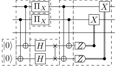
Implementing the circuit in Figure 1 with computational basis states as inputs would not be a good demonstration of quantum computing, as the state would not exhibit superposition or entanglement throughout the computation. In order to remedy this, we input the state , thus preparing the equal superposition of all four two-bit sums, and obtaining the result of one of them at measurement time. We also replace the Toffoli gate with a ccz gate conjugated by Hadamards, which, after simplification, gives the circuit of Figure 2, which is the logical circuit we use in the remainder of this work.
In the following section, we review the error-detecting code selected for this work (the colour code). We express the logical circuit in terms of simple, low-overhead fault-tolerant operations in Section IV. We then implement the resulting circuit in an ion-trap quantum computer, comparing the arithmetic error rates achieved using fault-tolerant and non-fault-tolerant circuits, as well as simulations, in Section V. We discuss the resource overhead required for a variety of implementations of one-bit addition in Section VI, and conclude in Section VII.
III colour code
To encode the three logical qubits necessary for one-bit addition and gain access to a transversal ccz, we select the colour code [16].
To prepare a uniform superposition of valid one-bit sums, we first fault-tolerantly prepare the state. We then perform the transversal ccz, and a cnot between qubits and , then measure qubit in the basis, and finally measure qubits and in the basis. While the transversal ccz of the code is already well understood, the state preparation, Clifford gates and measurements used here have not been described in the prior literature to our knowledge. We explain their derivation below, in order of execution in the experiment.
IV Construction of the circuit
IV.1 Preparation
There is a well-known procedure for fault-tolerant preparation of states in CSS codes of distance involving measuring stabilisers with the state as input. The first round of measurement will result in random outcomes, so multiple rounds (two for codes with ) would be necessary to detect errors. For the code, this requires cnots and 8 measurements.
To reduce the size of this circuit, we use the Goto circuit design technique [17], first writing out a non-fault-tolerant circuit with the minimum number of two-qubit gates, then measuring a limited set of stabilizers that detect high-weight errors resulting from error propagation through the initial circuit. We find the non-fault-tolerant stage of the circuit by inspection, beginning from the desired final state and using cnot gates to break the state’s entanglement, until arriving at a state consisting of four Bell pairs, which can be prepared fault-tolerantly using cnots on bare qubits. We confirm that this circuit contains the minimum number of cnots using breadth-first search over an implicit graph whose vertices are canonical stabilizer states (see [18], [19]).
Gottesman-Knill simulation reveals that all high-weight propagated errors can be detected by fault-tolerant measurement of two weight-four stabilisers, and . This can be accomplished using an appropriately interleaved circuit designed by Reichardt [20]. The final preparation circuit requires 18 cnots and two measurements, halving the number of relatively error-prone gates with respect to the generic technique.
IV.2 Destructive Measurement
Similarly to state preparation, there is also a generic protocol for measuring the logical observables of CSS codes. In this protocol, all data qubits are measured in the or basis, and the eigenvalues of stabilisers and logical operators in that basis are then reconstructed by calculating classical parities, allowing a final round of classical error correction to be performed. In this way, any set composed only of tensor products of or operators can be measured, but we cannot simultaneously measure and using this protocol.
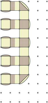
Typically, whenever we wish to measure a subset of logical qubits in a different basis, we use an ancilla-based circuit to measure the relevant operators in a non-destructive, fault-tolerant way (similarly to stabilizer measurements) or synthesize the logical measurement by transferring the relevant subset of logical qubits to a new code block, which may subsequently be measured destructively. The colour code allows an alternative to such a protocol; a logical operator supported on a face may be measured destructively by measuring the four qubits on that face in the basis. The remaining operators are reduced to weight two, and the weights of the operators not supported on the measured face are preserved, leaving the remaining two logical qubits encoded in the code, see Figure 4.
This destructive measurement is not fault-tolerant because no stabiliser eigenvalue can be reconstructed from the measurement outputs. To reconstruct , we use a flag-based circuit to non-destructively measure on the opposite face and take the parity of the five measurement outputs to reconstruct the stabilizer eigenvalue.
IV.3 Logical CNOT by Permutation
With CSS codes that encode a single logical qubit, such as surface code patches, entangling operations are implemented across different code blocks, usually using transversal gates or lattice surgery [21]. For codes such as the code, which possess logical qubits, there is no general protocol for performing logical entangling operations within a single code block (though architectures which use codes with have been explored [22]).
However, the colour code possesses a logical cnot gate which can be implemented by permuting or relabelling the physical qubits. This is due to a spatial symmetry of the stabilizer group which the logical operators do not obey. The QCCD architecture [23, 2] allows us to transport physical qubits from one area of a device to another if necessary. As a result, the cnot gate given in Figure 2 can be implemented with near-unit fidelity using only transport operations, see Figure 5.
V Experimental Results
V.1 Experimental details
The circuit given in Figure 6, which is a fault-tolerant implementation of the one-bit adder circuit, was submitted to both the Quantinuum H1-1 quantum computer and the Quantinuum H1-1E emulator. Upon submission, a compiler transforms the circuit into one corresponding to the native gate set of the quantum computer. For comparison, a non-fault tolerant circuit acting on three physical qubits, given in Figure 7, was also submitted to the device. The resulting circuits were executed 10,000 times on the quantum computer and 100,000 times on the emulator, and the results presented in Table 1.
| Shot frequencies | Non-fault-tolerant | Fault-tolerant | ||
|---|---|---|---|---|
| Device | Emulator | Device | Emulator | |
| 000 | 25.18% | 24.64% | 24.49% | 24.98% |
| 001 | 0.14% | 0.30% | 0.03% | 0.01% |
| 010 | 25.23% | 24.86% | 25.52% | 25.15% |
| 011 | 0.07% | 0.19% | 0.02% | 0.008% |
| 100 | 0.41% | 0.46% | 0.02% | 0.012% |
| 101 | 24.52% | 24.58% | 24.75% | 24.87% |
| 110 | 24.14% | 24.70% | 25.15% | 24.95% |
| 111 | 0.31% | 0.27% | 0.01% | 0.01% |
| Shot total | 10000 | 100000 | 8998 | 88537 |
| Arithmetic error rate | 0.95±0.19% | 1.22±0.07% | 0.11±0.07% | 0.04±0.014% |
The implementations of logical operations discussed in the previous section allow us to write a fault-tolerant implementation of one-bit addition in the colour code using 24 cnots and 12 measurements 111Single-qubit operations are not counted for the purpose of estimating the final logical error rate, due to their much lower error rates., see Figure 6. For comparison, decomposing the one-qubit adder into cnots and single-qubit gates on bare qubits results in five cnots and three measurements, see Figure 7.
To completely characterize the logical errors which occur in a fault-tolerant one-qubit addition, performing three-qubit logical process tomography would be necessary. However, process tomography results in prohibitively high sampling overhead and introduces the challenge of distinguishing state preparation and measurement (SPAM) errors from those occurring in the unitary of interest. For these reasons, we instead execute a complete protocol consisting of state preparation, unitary operations and measurements, and calculate an operationally-defined error rate which is affected by all steps of the process. At the end of each summation, we measure the register in the computational basis, at which point we learn classical values for the one-bit number , and the two-bit number . If
| (1) |
we can infer that a logical error has occurred. We call these events arithmetic errors and compare the rates at which they occur in Table 1.
In order to evaluate the effectiveness of the arithmetic error rate as a measure of the true error rate, we attempt to estimate the true error rate. This cannot be done directly from the data presented in Table 1. Therefore, we carry out a density-matrix-based simulation of the circuit, using a noise model motivated by that of the Quantinuum H1-1 emulator, and attempt to quantify the effect of noise on the state obtained at the end of the circuit. We obtain an arithmetic error rate of 0.39%, which is of comparable magnitude to that observed in Table 1. The fidelity of the simulated state with the ideal error-free state 99.7%, which implies that the use of the arithmetic error rate does not conceal significant logical errors in other bases.
VI Comparison With Planar Architectures
To understand the overhead reduction achieved in this implementation, we investigate a surface-code-based implementation of a one-bit addition for surface code patches with distance . Similar to [25], logical qubits are realised in independent code blocks, logical Clifford gates are implemented using lattice surgery, and the logical Hadamard is propagated forward, resulting in an measurement on the third qubit at the end of the circuit. We can lower the overhead of this implementation by generating the state using a magic state factory [26], and computing with it directly, rather than using it for gate teleportation. At distance , the factory can detect any single-qubit error during the production of the state.
The overhead of this implementation is dominated by the ccz magic state factory. It requires 18 surface code patches to implement, which at distance implies physical qubits. This figure is over an order of magnitude higher than that of the code implementation discussed above and is too large to be executed on a Quantinuum H-series device at time of writing.

The relative logical error rates resulting from the use of such different state factories can be estimated by counting pairs of faults that result in logical errors (larger sets of independent faults being much less likely). We carry this estimation out using QuantumClifford.jl [19], resulting in 84873 fault pairs for the surface code, and 1116 for the code. While a more detailed comparison would not apply to devices of either architecture, we can see that the number of malicious pairs is far greater than the number of malicious pairs for the -code-based implementation, which suggests that higher code distance (and greater overhead) would be necessary to match the logical error rate obtained in this work.
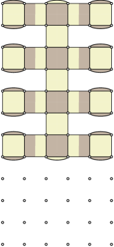
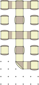
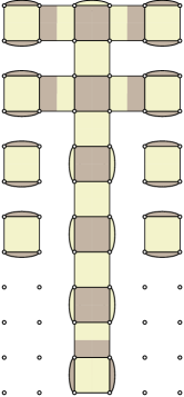
By contrast, implementing one-qubit addition using the colour code on a device with square-lattice connectivity can be accomplished with moderate overhead using the qubit layouts in Figure 9. The initial layout is used for non-fault-tolerant state preparation, and four cnots are then required to change the layout so that the remainder of the experiment can be carried out. After non-fault-tolerant state preparation, the stabilizer measurement requires an additional six cnots, since the swap gates must be decomposed into cnots rather than replaced with transport operations. While these additional cnots represent a significant increase in the overall size of the circuit without increasing its ability to tolerate errors, the induced overhead is not as significant as implementing the computation with surface-code-based logical qubits.
VII Discussion & Conclusion
The fault-tolerant implementation of one-bit addition demonstrates the combined effect of transversal non-Clifford gates, logical Cliffords by permutation, post-selected state preparation, and omission of error-correction gadgets in a fault-tolerant computation. While we cannot expect each of these techniques to result in the same logical error rate reduction in all fault-tolerant computations, we believe that each of them will contribute to lower logical error rates and overheads in some future fault-tolerant computations. This result also highlights the peculiar ‘inversion of difficulty’ in fault-tolerant quantum computing. That is, the operations that induce the most error at the physical level (cnot and ccz) can be carried out fault-tolerantly using high-fidelity transport and transversal single-qubit gates. In contrast, state preparation (which is comparatively simple and reliable at the physical level) comprises most of the fault-tolerant circuit, causing a large fraction of logical errors.
This demonstration also highlights several open problems to address in future work. For instance, this experiment uses post-selection rather than correction and achieves a low conditional probability of error with moderate () post-selection overhead. Full post-selection (i.e. accepting the output only if no syndrome is observed) on every fault-tolerant gadget would result in an exponentially decaying acceptance probability. Still, the effect of partial post-selection (accepting syndromes that indicate an error with weight on selected gadgets within a larger algorithm) has yet to be explored.
In addition, the placement of QEC gadgets between every adjacent pair of fault-tolerant operations is sufficient to prove the existence of thresholds in the ExRec formalism [6]. However, it is not necessary to do this to make a circuit fault-tolerant. Omitting QEC gadgets (or using partial QEC gadgets, as in Appendix A) between consecutive fault-tolerant operations can reduce logical error rates and overheads in a wide variety of protocols.
Finally, we note that the fault-tolerant protocol we have developed leverages all-to-all connectivity of the physical qubits, and exhibits relatively high pseudothresholds for certain quantum computing tasks, making it particularly suitable for other platforms with high qubit connectivity, such as neutral atoms [27, 28] and NV-based networks [29, 30]. A similar idea has recently been proposed to implement quantum low-density parity-check codes (qLDPC) using reconfigurable atom arrays [27]. By using the product structure inherent in many qLDPC codes to implement non-local syndrome extraction circuits via atom rearrangement, effectively constant overhead in practically relevant regimes can be achieved [27].
Acknowledgements.
The authors thank Andrew Landahl for inspiring this project, as well as Ross Duncan, Chris Self, Ciarán Ryan-Anderson, and David Hayes for helpful comments and insightful discussions during the preparation of this work, and Karl Mayer for illuminating discussions regarding the noise model used on the Quantinuum H1-1 emulator. This publication is part of the QuTech NWO funding 2020-2024 - Part I “Fundamental Research” with project number 601.QT.001-1, which is financed by the Dutch Research Council (NWO). Y. Wang would like to acknowledge the funding support from BMBF (Grant No. 16KIS1590K). Note added: We would like to bring the reader’s attention to a related work by Menendez at al., “Implementing fault-tolerant non-Clifford gates using the [[8, 3, 2]] color code”, which appears in the same arXiv posting.References
- Montanaro [2016] A. Montanaro, npj Quantum Information 2, 1 (2016).
- Pino et al. [2021] J. M. Pino, J. M. Dreiling, C. Figgatt, J. P. Gaebler, S. A. Moses, M. S. Allman, C. H. Baldwin, M. Foss-Feig, D. Hayes, K. Mayer, C. Ryan-Anderson, and B. Neyenhuis, Nature 592, 209 (2021).
- [3] IBM Newsroom, IBM Unveils Breakthrough 127-Qubit Quantum Processor, https://newsroom.ibm.com/2021-11-16-IBM-Unveils-Breakthrough-127-Qubit-Quantum-Processor.
- Qua [2022] Quantinuum System Model H1 Product Data Sheet. Version 5.20, https://www.quantinuum.com/hardware/h1 (2022).
- Shor [1996] P. Shor, in Proceedings of 37th Conference on Foundations of Computer Science (1996) pp. 56–65.
- Aliferis et al. [2005] P. Aliferis, D. Gottesman, and J. Preskill, (2005), arxiv:quant-ph/0504218 .
- Ryan-Anderson et al. [2021] C. Ryan-Anderson, J. G. Bohnet, K. Lee, D. Gresh, A. Hankin, J. P. Gaebler, D. Francois, A. Chernoguzov, D. Lucchetti, N. C. Brown, T. M. Gatterman, S. K. Halit, K. Gilmore, J. Gerber, B. Neyenhuis, D. Hayes, and R. P. Stutz, (2021), arxiv:2107.07505 [quant-ph] .
- Ryan-Anderson et al. [2022] C. Ryan-Anderson, N. C. Brown, M. S. Allman, B. Arkin, G. Asa-Attuah, C. Baldwin, J. Berg, J. G. Bohnet, S. Braxton, N. Burdick, J. P. Campora, A. Chernoguzov, J. Esposito, B. Evans, D. Francois, J. P. Gaebler, T. M. Gatterman, J. Gerber, K. Gilmore, D. Gresh, A. Hall, A. Hankin, J. Hostetter, D. Lucchetti, K. Mayer, J. Myers, B. Neyenhuis, J. Santiago, J. Sedlacek, T. Skripka, A. Slattery, R. P. Stutz, J. Tait, R. Tobey, G. Vittorini, J. Walker, and D. Hayes, (2022), arXiv:2208.01863 [quant-ph] .
- Postler et al. [2022] L. Postler, S. Heußen, I. Pogorelov, M. Rispler, T. Feldker, M. Meth, C. D. Marciniak, R. Stricker, M. Ringbauer, R. Blatt, P. Schindler, M. Müller, and T. Monz, Nature 605, 675 (2022).
- Litinski and von Oppen [2018] D. Litinski and F. von Oppen, Quantum 2, 62 (2018).
- [11] B. Pokharel and D. Lidar, arXiv:2211.04543 .
- Gottesman and Chuang [1999] D. Gottesman and I. L. Chuang, Nature 402, 390 (1999), arxiv:quant-ph/9908010 .
- Bravyi and Kitaev [2005] S. Bravyi and A. Kitaev, Physical Review A 71, 022316 (2005), arxiv:quant-ph/0403025 .
- Landahl [2022] A. Landahl, Personal communication (2022).
- [15] L. K. Grover, in Proceedings of the Twenty-Eighth Annual ACM Symposium on Theory of Computing, STOC ’96 (Association for Computing Machinery) pp. 212–219.
- Campbell [2016] E. T. Campbell, The smallest interesting colour code, https://earltcampbell.com/2016/09/26/the-smallest-interesting-colour-code/ (2016).
- Goto [2016] H. Goto, Scientific Reports 6, 19578 (2016).
- Scheinerman [2022] E. Scheinerman, ImplicitGraphs, https://github.com/scheinerman/ImplicitGraphs.jl (2022), commit 14459d3.
- Qua [2023] QuantumClifford.jl, Quantum Savory (2023).
- Reichardt [2020] B. W. Reichardt, Quantum Science and Technology 6, 015007 (2020), arxiv:1804.06995 [quant-ph] .
- Terhal [2015] B. M. Terhal, Reviews of Modern Physics 87, 307 (2015), arxiv:1302.3428 [quant-ph] .
- Brun et al. [2015] T. A. Brun, Y.-C. Zheng, K.-C. Hsu, J. Job, and C.-Y. Lai, (2015), arXiv:1504.03913 [quant-ph] .
- Kielpinski et al. [2002] D. Kielpinski, C. Monroe, and D. J. Wineland, Nature 417, 709 (2002).
- Note [1] Single-qubit operations are not counted for the purpose of estimating the final logical error rate, due to their much lower error rates.
- Litinski [2019] D. Litinski, Quantum 3, 128 (2019), arxiv:1808.02892 [cond-mat, physics:quant-ph] .
- Gidney and Fowler [2019] C. Gidney and A. G. Fowler, Quantum 3, 135 (2019).
- Xu et al. [2023] Q. Xu, J. P. B. Ataides, C. A. Pattison, N. Raveendran, D. Bluvstein, J. Wurtz, B. Vasic, M. D. Lukin, L. Jiang, and H. Zhou, (2023), arXiv:2308.08648 [quant-ph] .
- Evered et al. [2023] S. J. Evered, D. Bluvstein, M. Kalinowski, S. Ebadi, T. Manovitz, H. Zhou, S. H. Li, A. A. Geim, T. T. Wang, N. Maskara, H. Levine, G. Semeghini, M. Greiner, V. Vuletic, and M. D. Lukin, (2023), arXiv:2304.05420 [quant-ph] .
- Wang [2023] Y. Wang, Using spins in diamond for quantum technologies, Ph.D. thesis, Delft University of Technology (2023).
- Hermans et al. [2022] S. L. N. Hermans, M. Pompili, H. K. C. Beukers, S. Baier, J. Borregaard, and R. Hanson, Nature 605, 663 (2022).
- Shi [2003] Y. Shi, QIC 3, 84 (2003).
- Eastin and Knill [2009] B. Eastin and E. Knill, Phys. Rev. Lett. 102, 110502 (2009).
- Horsman et al. [2012] D. Horsman, A. G. Fowler, S. Devitt, and R. V. Meter, New Journal of Physics 14, 123011 (2012).
- Hastings and Haah [2018] M. B. Hastings and J. Haah, Phys. Rev. Lett. 120, 050504 (2018).
- Knill [2005] E. Knill, Nature 434, 39 (2005).
Appendix A Logical Hadamard gates on the code
The selection of the code is motivated by its transversal logical ccz gate, which is desirable for achieving fault-tolerant universal quantum computation. The set is known to be universal [31], but cannot be performed transversally in a distance-2 code [32]. In the one-bit addition circuit, the logical Hadamard gates can be assimilated into adjacent state preparation or measurement steps. However, we cannot expect this to be the case for an arbitrary circuit. In general, it is possible to implement a Hadamard gate, or other Clifford gate, by fault-tolerantly preparing a Pauli eigenstate, and non-destructively projecting onto eigenspaces of logical Pauli operators, similarly to lattice surgery [33].
Such a construction is likely to outperform state-of-the-art magic state distillation methods [34] in terms of overhead for a wide variety of codes. However, there exists an alternative construction for the code, using fewer qubits and gates overall. We describe this low-overhead fault-tolerant implementation of the logical Hadamard in the remainder of this appendix.
| Stabilizers | |||||||||||||
| Stabilizers | |||||||||||||
A.1 Interaction with the code
Due to the inherent difficulty in directly implementing logical Hadamard gates on the encoded qubits of the code, it is natural to explore an alternative approach. One potential solution involves teleporting quantum states from one code to another, where the implementation of logical Hadamard gates is easier. The resulting state can then be teleported back to the original code block, completing the process.
To serve as the target for the teleportation process, an advantageous choice is a error-detecting code, with its corresponding stabilizers and logical operators listed in Table 2. The selection of the code is motivated by two crucial factors. Firstly, the logical cnot between two encoded qubits of the code and the two encoded qubits of the is transversal (see Fig. 11). This transversal gate greatly facilitates teleportation between these two codes. Secondly, the code offers the advantage of easily preparing eigenstates of logical Pauli operators [35].
The presence of two logical qubits in the block allows the implementation of two simultaneous logical Hadamard gates through teleportation, we describe the circuit for this operation in the following subsection, before concluding with the implementation of a single logical Hadamard.
A.2 Double logical Hadamard
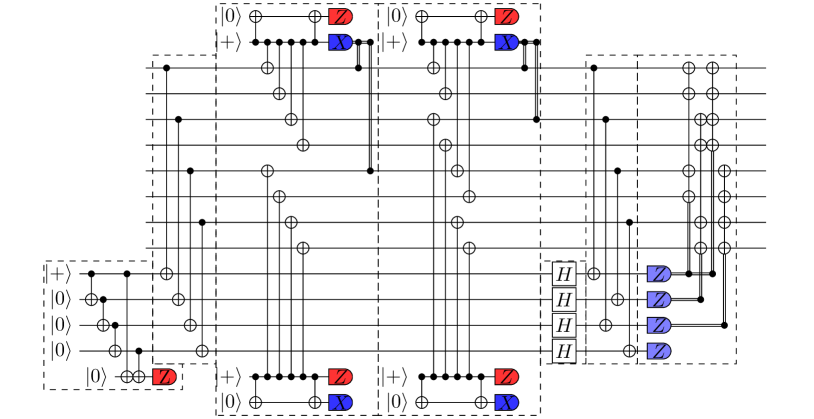
Here, we consider a logical Hadamard gate acting on logical qubits 1 and 2 of the code simultaneously. Note that, by symmetry, any other pair of logical qubits could be chosen, and the resulting circuit would be identical up to a permutation of physical qubits. At the logical level, this consists of preparing the state of the code, performing the transversal cnot, non-destructively projecting logical qubits 1 and 2 to the state , carrying out the logical Hadamard on the block, and teleporting the resulting states back to the block, using destructive logical measurement on the unneeded block (see Fig. 12). Each of these operations can be implemented at the physical level using transversal gates and flag circuits, without requiring a QEC gadget (see Fig. 13).
A.3 Single logical Hadamard
To implement a logical Hadamard gate on a single qubit, we change the initial state on the code to , and project only one logical qubit of the code into the state. Otherwise, the circuits implementing this gate are quite similar at both the logical and physical levels, see Fig. 14 and Fig. 15, respectively.