6G Radio Testbeds: Requirements, Trends, and Approaches
††footnotetext: This manuscript has been accepted for MTT-S TC-23 Wireless Communications Focus Issue of the IEEE Microwave Magazine.• Gilles Callebaut, Department of Electrical Engineering, KU Leuven, BE-9000 Ghent, Belgium, Email: gilles.callebaut@kuleuven.be, ORCID: 0000-0003-2413-986X. • Liang Liu, Department of Electrical and Information Technology, Lund University, SE-22100 Lund, Sweden, Email: liang.liu@eit.lth.se, ORCID: 0000-0001-9491-8821. • Thomas Eriksson, Department of Electrical Engineering, Chalmers University of Technology, SE-41296 Göteborg, Sweden, Email: thomase@chalmers.se, ORCID: 0000-0002-2087-7227. • Liesbet Van der Perre, Department of Electrical Engineering, KU Leuven, BE-9000 Ghent, Belgium, Email: liesbet.vanderperre@kuleuven.be, ORCID: 0000-0002-9158-9628. • Ove Edfors, Department of Electrical and Information Technology, Lund University, SE-22100 Lund, Ove.Edfors@eit.lth.se, ORCID 0000-0001-5966-8468. • Christian Fager, Department of Microtechnology and Nanoscience, Chalmers University of Technology, SE-41296 Göteborg, Sweden, Email: christian.fager@chalmers.se, ORCID: 0000-0001-8228-0736.
I Why 6G is wished for and needs new testbeds
The proof of the pudding lies in eating, that is why 6G testbeds are essential in the progress towards the next generation of wireless networks. Theoretical research towards 6G wireless networks proposes advanced technologies to serve new applications and drastically improve the energy performance of the network. Testbeds are indispensable to validate these new technologies under more realistic conditions. This paper clarifies the requirements for 6G radio testbeds, reveals trends, and introduces approaches toward their development.
The sixth-generation of mobile networks is expected to be introduced starting 2030. Research and development toward this novel generation of networks started several years ago in different regions of the world, e.g., [2]. A myriad of applications and novel use cases, ranging from augmented reality (AR) and mixed reality (MR) in professional and entertainment contexts to support autonomous systems and connecting a massive number of battery-less devices, are envisioned to be served by these networks [3]. The analysis of these use cases has led to a harmonized view of which functions and capabilities 6G networks should offer. Summarizing, the desired features for 6G can be classified into three main categories:
-
1.
Improving diverse wireless network services: delivering higher throughput and network capacity, ultra-reliable operation, imperceptible latency, and connectivity to many devices with an extremely low-energy budget.
- 2.
-
3.
Enhancing coverage: delivering more uniform and truly ubiquitous services.
In addition to new features, the intent for 6G has been expressed to improve energy efficiency by several orders of magnitude with respect to previous generation technologies, in order to keep up with the increasing volumes of mobile data without an associated increase in carbon footprint. More holistic value-related targets are being discussed regarding the dual notions of a sustainable 6G, and 6G for sustainability.
To support the above, novel technologies need to be developed for 6G networks [6]. Candidate technologies receiving focus from the academic and industrial community are:
- •
- •
-
•
The use of Artificial Intelligence (AI) technologies to increase performance and cope with the increased complexity in the networks [15].
-
•
Reflective intelligent surface (RIS) as a technology [16], to contribute to improving consistent coverage, which is especially challenging at millimeter wave (mmWave) frequencies and above.
-
•
Integration of terrestrial and non-terrestrial networks [17].
Experiments in testbeds can complement and strengthen theoretical work by providing validation under more realistic conditions, and hence increase the confidence level in these newly introduced technologies. Moreover, and at least as important, quite often these experiments reveal limitations or raise doubt about theoretical models or assumptions made. To test these assumptions and theoretical models under more realistic conditions, we require space, time, and actual hardware in order to represent ’real-life’ deployment scenarios. Therefore, we use this definition for a wireless testbed: “an experimental environment in which tests can be performed over real propagation channels, using real hardware and possibly operating in real-time”.
Innovative transmission schemes need to be developed to a higher technology readyness level (TRL) for testbed implementation. In this process, it is possible to refine models to better represent reality. Also, it allows developing models for and assess the sensitivity to hardware impairments. At the same time, testbeds typically provide much more flexibility and openness, potentially both in terms of hardware and data, than commercial systems. From that perspective, testbeds also contribute to a better technological understanding for the broad R&D community.
As the technological progress towards 6G has been intensifying, it is essential to also develop new testbeds for 6G networks for two main reasons: (i) to validate new technologies that were not present in previous generations raises new requirements on the testbeds to validate these, and (ii) the development of testbeds in itself often presents a first attempt and preview on challenges that will be encountered in real deployments.
I-A Scope
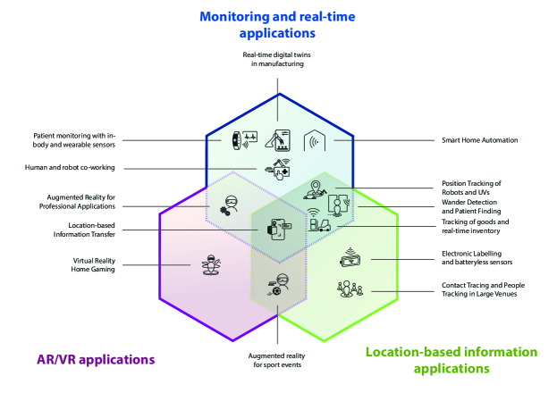
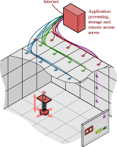
We focus on the validation of the new radio access, i.e., wireless, solutions to provide widely available high-performance services, in terms of capacity and reliability. Typical interactive applications to be served in dense interconnected environments range from real-time monitoring and AR/virtual reality (VR) to location-based information applications, as illustrated in Fig. 1. The key candidate technology to provide this performance is expected to be extreme distributed MIMO (D-MIMO), operating in frequency bands below . As a first contribution, this paper provides an overview of the corresponding 6G testbed requirements, based on the expected technological innovation that will be at the foundation of 6G networks and new functionalities to be supported. Further, it explains several complementary approaches to construct and operate scalable 6G testbeds to validate diverse functions and capabilities. Potential approaches to achieve synchronization are detailed, as experience in actually building testbeds shows that this poses a main, if not the main, challenge for D-MIMO. Targets for 6G testbeds are broad, as the envisioned ‘network of networks’ will among others include both terrestrial and non-terrestrial components and serve applications with frequencies up to sub-THz [3]. While the latter paper clarifies 6G requirements, we here focus on how to attain these are addressed in the testbeds. All anticipated propagation scenarios and frequency bands for 6G [18] can not be validated in one testbed. The approaches presented in this paper are targeted to the radio access technologies that are expected to become the main capacity bearer for the so-named extreme experience services [2]. Complementary testbed developments focus on operation in very high frequency bands [19] and [20], or on higher layer networking technologies, e.g., software-defined network (SDN) [21, 22].
I-B Different levels of testbeds
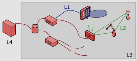
As discussed in the previous section, 6G presents a myriad of new research challenges, each having different scales, aims, and performance metrics. In order to discuss the different testbeds, we distinguish them based on their scope and intention. An overview of these different levels and a common architecture is presented in Fig. 2. Following the terminology introduced in [10], a 6G system architecture could exist out of several connected edge computing service points (ECSPs), which coordinate one or multiple contact service points (CSPs) and perform joint processing. The term CSP was introduced to indicate that the conventional access point (AP) is expected to support more than just communication in 6G, e.g., wireless power transfer (WPT). This implies that these CSPs will host a variety of hardware such as radio, charging, processing, data storage and other sensing elements. We categorized four levels of testbeds based on their capabilities and intended use, as illustrated in Fig. 2 and elaborated below.
Level 1 Testbed - Point-to-point (P2P) Link Evaluation
Moving to higher frequencies requires studying P2P link operation to test new hardware architectures. For instance, [23] [23] present a reconfigurable tile-based antenna array system for mmWave frequencies. It enables studying different beamforming (BF) architectures such as analog and hybrid BF, antenna positioning and layout at both the base station (BS) and user equipment (UE). Furthermore, given that users will be potentially in near-field in D-MIMO, novel wavefront designs need to be developed and tested in real scenarios, e.g., Bessel beamforming [24]. Point-to-point sub-THz communication experiments also belong to this category. Additionally, new fronthaul media for connecting the distributed CSP and ECSP nodes are being investigated. Analog- and various digital radio-over-fiber (RoF) techniques are expected to play an important role [25, 26, 27]. These two examples of L1 testbeds are depicted in blue in Fig. 2.
Level 2 Testbed - Channel Sounders
To study the new propagation conditions as an effect of distributing resources, moving to higher carrier frequencies [18] and having an increased number of antenna elements with respect to conventional mMIMO, channel sounders are used. In essence, a channel sounder consists of one or more transmitter (TX) and receiver (RX) chains, where the transmitted signals are recorded at the RX, and processed to investigate the propagation channel, as illustrated in green in Fig. 2. Different approaches are used to sample the channel. Virtual arrays can be created by moving a single antenna to multiple locations. Another approach is to have multiple antennas connected to one radio frequency (RF) chain, where the antennas are time-multiplexed via an RF switch. For example, in [12], [12] study the path loss (PL) models, channel impulse response (CIR), coherence time, and more, in different environments and wall materials with a RF-switched 16-antenna channel sounder operating at .
Level 3 and 4 Testbeds
In contrast to the channel sounders, real-life (L3) testbeds do not require fine-grained propagation channel knowledge, such as for example angle-of-arrival (AOA), but are designed to investigate end-to-end communication performance, as for instance the network’s energy-efficiency. In L3 testbeds, real-life measurements are conducted and processed in an offline stage. L4 testbeds extend L3 by supporting real-time processing of signals to evaluate algorithms requiring real-time interaction between the network and the UEs, unable to be performed offline. This is further discussed in Section II-A. The real-time operation (L4), in contrast to L3 testbeds, is highlighted by the use of a real-time processing infrastructure in Fig. 2.
II Moving from 5G to 6G – Challenges and Requirements for 6G Testbeds
Here, the new requirements for 6G testbeds with respect to previous generations are discussed. As motivated in Section I, 6G testbeds are required to enable research evaluating new technologies and architectures, therefore our focus will be on testbeds targeting Level 3 and 4. Specifically, the move towards a distributed deployment in 6G, necessitates a number of new methods to cope with, including i) the geographical dispersion of processing resources and ii) the high number of CSPs. On top of this, providing real-time operation of a D-MIMO testbed imposes new challenges.
II-A Offline vs. real-time signal processing
Both offline and real-time signal processing are important features for a 6G testbed. Offline processing requires the capability of recording data for a certain time interval for later analysis, giving the flexibility to develop and evaluate a wide range of signal-processing algorithms. On the other hand, real-time processing enables system measurement and testing in fast-changing environments. The real-time (L4) testbed can also serve as the system-level tester for hardware solutions of specific function blocks (e.g., digital signal processors, data converters, and transceivers).
The first challenge for real-time signal processing is the high throughput requirement. For instance, depending on the selected algorithms, the required processing capability to support real-time multi-user detection can grow exponentially with the number of BS antennas and the number of simultaneously served users. Processing latency is another challenge for real-time testbeds, especially for time-critical use cases and/or in fast-changing environments. There are two processing latency constraints when developing a real-time testbed. The first one is the end-to-end latency, e.g., TX-to-RX, which is bounded by application requirements. For applications such as real-time digital twins in manufacturing, and human and robot co-work, the end-to-end latency should be around [28]. The second latency constraint relates to time division duplexing (TDD) switching time in reciprocity-based mMIMO. The process of channel estimation using uplink pilots, calculating precoding coefficients, and transmitting the precoded data all need to be finished within the time interval between the uplink pilot and downlink data in a radio frame [29]. This time interval can be in the sub-millisecond range, depending on the supported coherence time and thus the radio frame structure. For instance, the processing latency constraint is around to support mobility at [29]. The latency requirement is even more critical for decentralized processing architectures, where the data transfer between processing units may take a substantial amount of time.
II-B Moving to distributed processing architectures
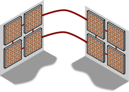
Independent of the physical locations of the antennas (co-located or distributed), there are various processing strategies that can be applied, affecting the data transfer between processing units in different ways. Here we will focus on the two main processing strategies, namely centralized and decentralized processing [30, 31], as illustrated in Fig. 3. The centralized solution faces critical implementation challenges when up-scaling the number of antennas and the signal bandwidth, especially considering the aggregated data rate to the central processing unit. For a 6G mMIMO system with BS antennas, 25 single-antenna users, and bandwidth, the aggregated data rate reaches around , exceeding the data-rate limit of commonly available interconnection solutions. The aggregated data may be distributed over different physical links, however, the number of input/output (IO) connections is generally limited on a practical processing hardware platform. Next to dedicated interconnects, a candidate medium to convey the data is Ethernet, where software is being developed, e.g., Data Plane Development Kit (DPDK) [32], to enable high-throughput real-time data transfer.
Decentralized processing (including distributed processing algorithms and the corresponding distributed architectures) enables closer-to-antenna processing and avoids extensive data aggregation, and thus is more suited for scalable implementations. This method follows more closely a generic architecture, using ECSPs and CSPs as depicted in Fig. 2. For instance, the recursive least square algorithm is a decentralized implementation of the zero-forcing (ZF) detection, which is mapped to a Daisy-chain topology distributing the data only between neighboring processing units in the chain [30]. This, however, implies long processing latency to propagate the signal processing serially through the entire chain. This could be partially overcome by applying more parallel topologies, e.g., mesh and tree [31]. In physically distributed mMIMO systems, it is expected that numerous antennas are available around (and close to) the users, i.e., ECSPs. Algorithms with local-only processing, e.g., maximum ratio transmission (MRT), are likely to provide good enough system performance and approach the centralized ZF performance. The corresponding data transfer between processing units can then be minimized.
Data storage is another implementation challenge in the centralized solution. The required memory size to store the channel matrices of the mMIMO system is (24-bits per channel matrix element). In the distributed processing architecture, data storage can be distributed over many processing units, making it possible to use more cost and energy-efficient on-chip memory solutions for each processing unit.
II-C Calibration and Synchronisation
| Mechanism | Frequency | Phase | Time | D-MIMO | Carrier | Ref. | ||||
|---|---|---|---|---|---|---|---|---|---|---|
| Drift | Offset | Offset | Offset | Sub-10GHz | mmWave | |||||
| RF and BB PLL sharing | ||||||||||
| Reference clock (e.g., and 1PPS) | [33, 12, 34, 12] | |||||||||
| Ethernet-based | ||||||||||
| White Rabbit | [35, 34] | |||||||||
| Precision-time protocol (PTP) | [36, 33, 32] | |||||||||
| Over-the-air | ||||||||||
| UE-assisted sync | [37, 38] | |||||||||
| Beacon/anchor nodes | [39, 40] | |||||||||
| Radio-over-fiber | ||||||||||
| Analog | [25, 14] | |||||||||
| Digital () | [41, 42, 43] | |||||||||
A main challenge in most wireless systems in general, and in testbeds in particular, is calibration and synchronization. Here we use the word calibration in a general sense, including gain and phase calibration, linearization, in-phase/quadrature (I/Q) imbalance compensation, and impairment mitigation in general. Synchronization includes mismatch and drift related to the oscillators, e.g., phase, sampling time, and carrier frequency calibration. In a testbed, part of the calibration and synchronization can be done through offline procedures, using lab instruments. The calibration needs related to hardware are generally slow-varying compared to the rapid changes in the propagation channel, such that calibration procedures can be applied fairly infrequently [9]. However, it is usually necessary to re-calibrate the testbed when it is used, preferably only using the hardware in the testbed itself, potentially based on dedicated signals. In many cases, it is also desirable to study calibration itself, since it is an integral part of the achievable signal quality, i.e., through an L1 testbed. Below, we discuss approaches that have been proposed in literature, useful for calibration of a communication network, yet also possible to implement in a testbed for research.
Calibration
To calibrate a transmitter, it is necessary to capture the transmitted signal to enable later characterization and compensation, which is historically often achieved by observation receivers at the transmitter outputs. However, in a multi-antenna transmitter, the overall transmitted signal is a combination of all the antenna signals, and the output of individual transmitters is not representative of what the receivers will see. Further, with the development towards integrated systems, accessing the signals at the transmitter outputs can be difficult. These challenges require over-the-air (OTA) signal acquisition for calibration, generally through one or more external receivers.
With phased-array beamforming, needing knowledge of beam directions, absolute calibration is required, i.e., the transmitters and receivers are each calibrated to reach the desired linear operation as accurately as possible [44]. In contrast, for reciprocity-based communication, as in mMIMO, it is enough to ensure that TX and RX RF chains are reciprocal [45] using reciprocity calibration. This calibration can be done in collaboration with the UEs by pilot signalling [45], but it is preferable to avoid this. [46] [46] and [38] [38] have proposed to instead exchange pilots only between the CSPs by, possibly also with an additional external reference antenna. Alternatively, [47] [47] show that pilot-free calibration can be performed by exploiting antenna coupling. OTA linearization (i.e., compensation of nonlinear amplifiers) in a multiple-input multiple-output (MIMO) setting is studied in, e.g., [48]. The calibration challenge in D-MIMO is similar to the challenge in co-located MIMO. However, the issue of synchronization is more challenging for distributed systems; we discuss this below.
Synchronization
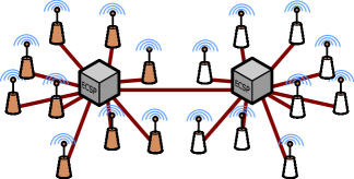
Synchronization, i.e., calibration connected to oscillators, is a crucial topic in communication networks. Table I summarizes methods for synchronization and indicates whether they are suited for co-located or distributed systems, as well as applicable to sub- or mmWave carrier frequencies. [49] [49] and [50] [50] also provide an overview of timing and carrier synchronization algorithms, for co-located and distributed MIMO systems. In a multi-user MIMO system, the UEs have their own independent oscillator, which poses multiple synchronization tasks for each CSP. With co-located MIMO, the oscillators or phase-locked loops (PLLs) can be shared among the antennas. However, in a D-MIMO system, this mechanism does not scale well with increased geographical distance between the CSPs. The synchronization is one of the critical issues in D-MIMO, and it is therefore of high priority to study in 6G testbeds.
Beamforming relies on multiple antennas, operating in a phase-synchronous way, such that the receivers experience constructive addition of multiple antenna signals. To achieve such phase-coherent downlink (DL) transmission, or uplink (UL) reception, carrier frequency, sample time and phase must be accurately synchronized. When the signals are not phase-aligned at the user, they no longer constructively interfere, degrading the signal power and quality. The techniques to obtain coherency can be divided into connected synchronization, i.e., using cables or optical fibers, or wireless OTA synchronization. Connected synchronization can be performed by sharing the RF oscillator between the radios. As mentioned, this is problematic for high frequencies and when the distances to remote antennas increases. An alternative is to share a low-frequency reference clock (e.g., at around ), which can be combined with a pulse per second (1PPS) signal. This approach is also used in the Techtile testbed, Section III-A. Another possibility, used in the millimeter-wave MIMO testbed (MATE) testbed Section III-C, is to distribute an intermediate-frequency (IF) clock which is frequency-multiplied at the antennas to the RF frequency. To improve the scalability further, Ethernet-based approaches can be implemented, such as White Rabbit (WR) [51]. This is illustrated in Fig. 4(a). To achieve a synchronized and phase coherent MIMO DL, an all-digital RoF solution using bandpass coding has been proposed [41], depicted in Fig. 4(b). Compared to analog RoF solutions, it enables a relatively simple and low-cost and low-complex implementation CSPs [43, 42, 26]. A D-MIMO testbed based on this approach is presented in Section III-B. There are also several OTA techniques proposed in the literature. Carrier frequency, sample time and phase can be estimated and compensated, using pilots shared with the UEs [38] or feedback signalling [37, 52]. Some proposals in the literature assume a beacon signal transmitted by a central node [39], potentially leading to problems when the number of CSPs are scaled up. Decentralized schemes, e.g., based on multiple anchor nodes, are studied in, e.g., [40, 36].
II-D UE data collection
To acquire the necessary signals at the UE, different platforms can be used. The primary function of such platforms is to navigate the UE data collection device to a predetermined position. For indoor environments, different rovers are deployed, often able to navigate in a 2D space [53, 54, 55, 56, 57]. Others [58, 33] have adopted, e.g., a scissor lift, to support automated 3D sampling. The position of the data collector platform is determined via simultaneous localization and mapping (SLAM) [58], light detection and ranging (LiDAR) [12], cameras [55, 53, 56], fixed marking [33, 57], mechanical positioners, e.g., CNC XY-table, or a combination of these techniques. In outdoor scenarios, drones [59, 54] or humans (pedestrians [54]) are used to move the UEs. Next to using drones to emulate UEs positions, [60] [60], use drones to represent multiple APs in a CF system. GNSS is often employed to acquire the position [59], sometimes extended with Real Time Kinematics (RTK) [54] to improve the location accuracy. As elaborated in [54], we also advocate acquiring multi-modal sensor measurements during data collection, such as weather conditions, images, and 3D LiDAR to support studying vision-aided algorithms for, e.g., beam and blockage prediction in mmWave systems [61].
II-E Open Testbeds
To facilitate widespread adoption and interoperability, 6G systems require open standards, interfaces, data sets, hardware, and software. We, here, highlight some endeavors made towards open 6G testbeds and networks.
II-E1 Open Interfaces, Non-Proprietary Hardware and Software
While not the focus of this work, open radio-access network (O-RAN), next to others, has emerged due to the need for interoperability and openness in next-generation networks. The emergence of open systems indicates a shift towards non-proprietary components in mobile/cellular network architectures. This includes the usage of commercial off-the-shelf (COTS) software-defined radios (SDRs). To this end, [62] [62] describe how to build an SDR-based testbed supporting the O-RAN architecture and interfaces. This is accomplished by introducing standard-compliant open-source software-defined radio access networks (RANs), such as srsRAN and OpenAirInterface (OAI) [63]. In [36], a CF implementation of O-RAN is presented, coined CF-RAN. They identify current implementation challenges such as time-frequency synchronization and reciprocity calibration, as handled in Section II-C in this work. Next to open interfaces, open commercial-grade software needs to be developed. In [64], a real-time mMIMO base-band (BB) processing software is presented, which is published in open-source. M-Cube [65] is an open hardware and software for a mmWave mMIMO SDR, where the board schematics, real-time phased array controller code, interfaces, and examples are all available.
II-E2 Open Data
Accompanying open testbed infrastructure and interfaces, open tools to process the generated (raw) data and the data itself should be accessible. In addition, the data ought to satisfy the FAIR principles [66], i.e., findability, accessibility, interoperability, and reusability. This entails that the data is accompanied by well-described metadata, documentation, and (preferably) open licenses. This information, together with the data, can then be hosted on an open data platform, such as IEEE DataPort, Open Data on AWS, Kaggle and data.europa.eu (DEU).
Examples in the field. RenewLab [67] is an open toolbox for processing mMIMO signals, used in the POWDER testbed [34]. DeepSense 6G [54] and LuViRA [56] are works describing measurements, including multi-modal sensors and well-described measurement campaigns, accompanied by an open dataset. All data sets generated by the COSMOS [68] testbed are published on their website. Due to the increase in available 6G simulators, datasets including ray-tracing-based results are being published, e.g., DeepMIMO [69] and the ViWi dataset [70].
III Testbed Approaches By Example
In this section, we address the aforementioned challenges and offer four examples of testbeds designed to meet specific testing and verification needs in emerging 6G systems. It is important to note that each of these presented testbeds addresses different requirements, leading to different implementations and design choices. To gain a better understanding of the discussed testbeds and their capabilities, see Table II. For a comprehensive comparison of additional 6G testbeds, you can find relevant information in [3].
| Capabilities | |||||||||
|---|---|---|---|---|---|---|---|---|---|
| Ref. | Antennas | Bandwidth | Frequency |
Communication |
WPT |
Localisation |
Open-Source |
D-MIMO |
Testbed Level |
| LuMaMi [29] | 100 | - | L4 | ||||||
| LuMaMi28 [71] | 16 | L4 | |||||||
| LuLIS (under dev.) | 256-1024 | L4 | |||||||
| KULMaMi [72] | 64 | - | L4 | ||||||
| Techtile [33] (under dev.) | 280 | - | L4 | ||||||
| Chalmers D-MIMO [43] | 12 | L3 | |||||||
| Chalmers MATE [73] | 16 | L1/L3 | |||||||
III-A Scalable Low-Cost D-MIMO Testbed
To study the impact on the architecture and performance of D-MIMO with low-cost COTS components, Techtile was constructed [33]. The room-sized testbed consists of tiles embedding computing devices, SDRs, and sensors. The testbed and its architecture is illustrated in Fig. 5. Techtile is fundamental in identifying and addressing key challenges in order to progress towards practically deployable D-MIMO/CF systems. These challenges stem from the high number of diverse resources hosted in the infrastructure and the novel application requirements.
Evaluation of co-located vs. distributed APs
As illustrated in Fig. 5, all tiles are connected via Ethernet cables to a central server. By doing so, the physical topology allows emulating different topologies, e.g., daisy chain. This feature facilitates exploring different algorithms related to data transfer, as elaborated in Section II-B. By increasing the number of antenna elements ( elements), the users are expected to operate closer to the antenna near-field in D-MIMO networks. With the physical large aperture of the testbed, this near-field operation can be investigated.
Synchronization and Calibration
Techtile currently supports Ethernet-based and dedicated cable-based synchronization. Fine-grained frequency, phase and time synchronization is obtained by distributing a and 1PPS signal to all tiles via NI Octoclocks. On top of this, the Ethernet infrastructure supports PTP for sub-microsecond time synchronization.
UE Data collection
Open Testbed
All developed software and hardware is available and documented on our GitHub webpage (www.github.com/techtile-by-dramco).
III-B Sigma-delta radio-over-fiber enabled D-MIMO testbed
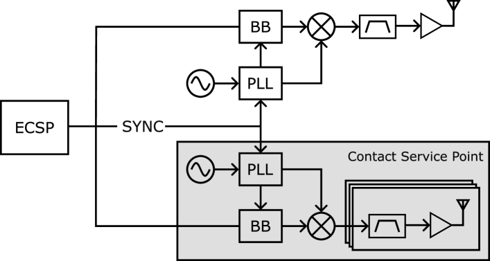
As discussed in Section II-C, one of the main challenges in realizing D-MIMO systems is to maintain precise synchronization between remote CSP. RoF is a technique that has been explored for realization of phase coherent synchronization in distributed antenna systems. Both digital- and analog implementations of RoF exist. Analog implementations, where the RF signal amplitude modulates the optical signal intensity, have the benefit of simple RF circuit implementation but suffer from limited dynamic range and complex optical implementations [26]. Digital RoF implementations, on the other hand, are robust against optical imperfections and benefit from the rapid evolution of standardized low-cost and ultra-high-speed digital optical interconnect solutions for data centers.
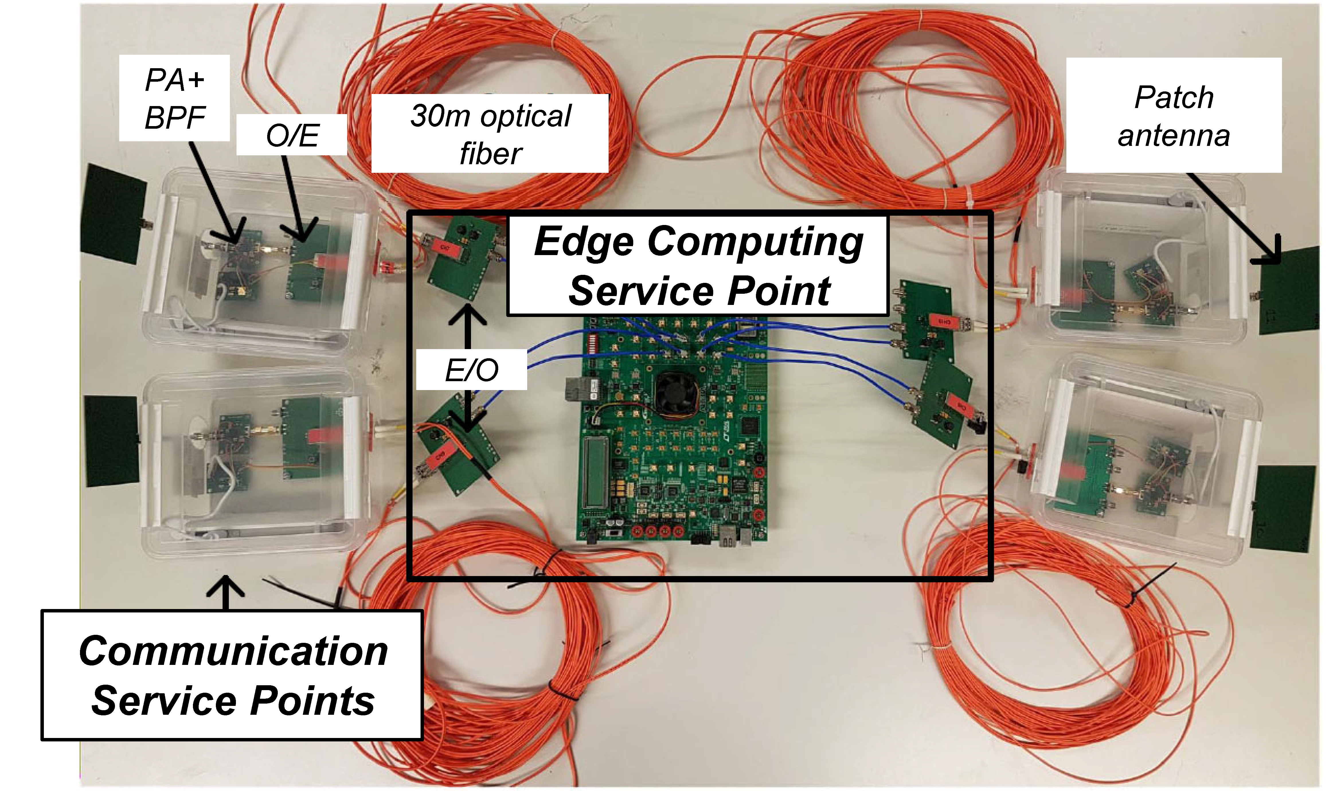
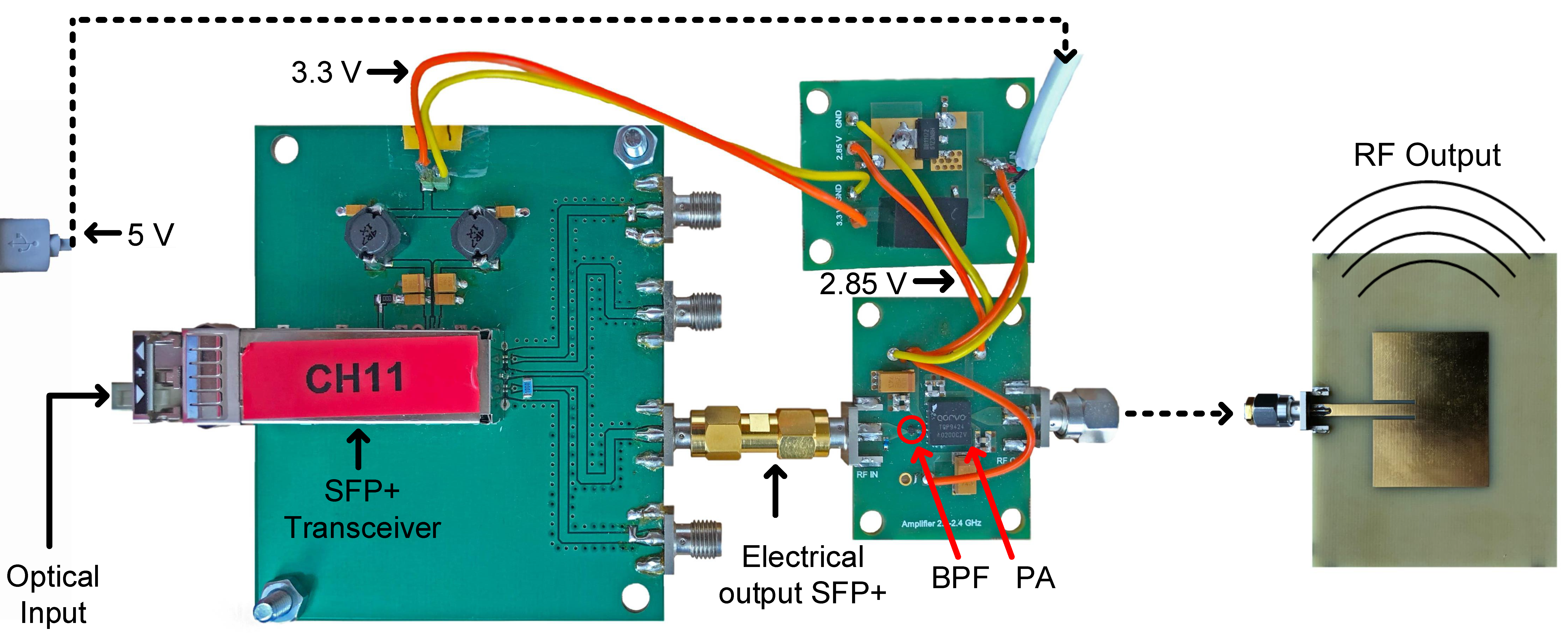
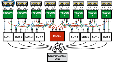
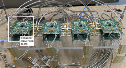
The SDoF technique is employed in [43] to realize a testbed suitable for D-MIMO DL experiments. As illustrated in Fig. 6(a), a ECSP (in this case an field-programmable gate array (FPGA)) feeds up to remote CSPs through small form-factor pluggable (SFP) optical links with individually coded bandpass -coded RF bitstreams. At the remote CSP, the signal is recovered from the bitstream through a bulk acoustic wave (BAW) bandpass filter, then amplified and fed to a patch antenna. As demonstrated in [43], the testbed can support up to bandwidth and maintains an root-mean-square (RMS) phase coherence below between the CSPs.
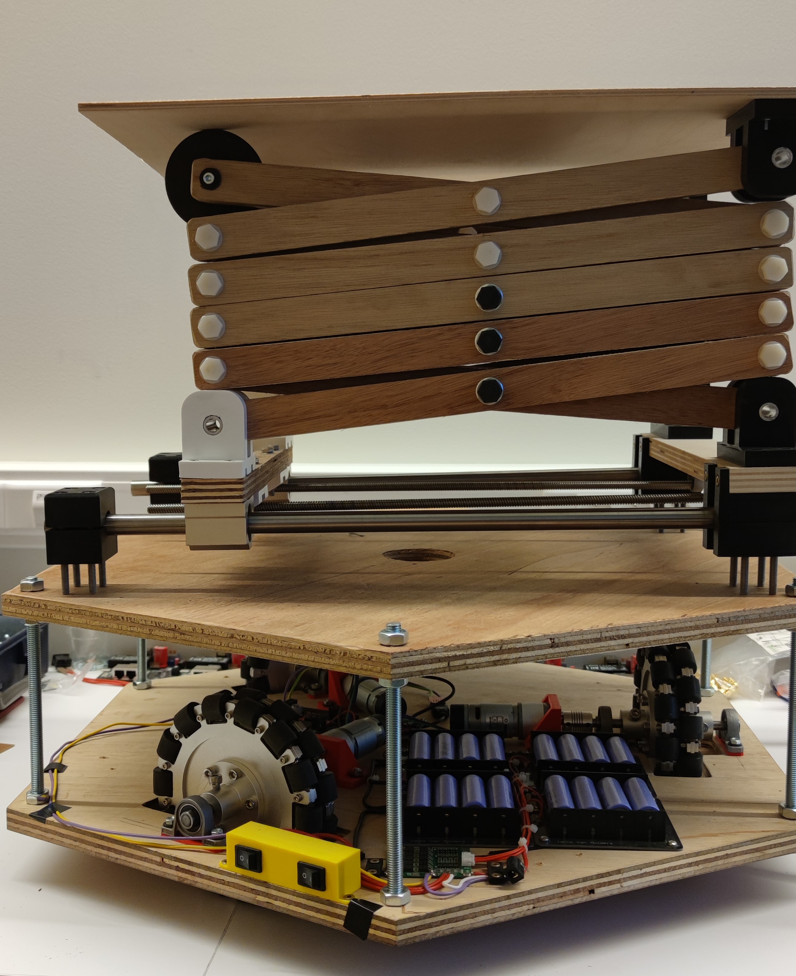
UE Data collection
To facilitate efficient collection of communication and channel data in realistic environments, the testbed has been extended with an UE robot in [57], see Fig. 6(c). The robot is controlled by a Raspberry Pi, an Ettus USRP radio receiver and optical sensors. The robot is programmed to follow a line on the floor/ground and, at intervals marked by perpendicular lines, collects over-the-air data and transmits it to the ECSP using Wi-Fi for communication signal processing.
Evaluation of co-located vs. distributed CSPs
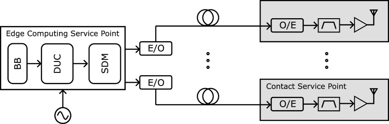
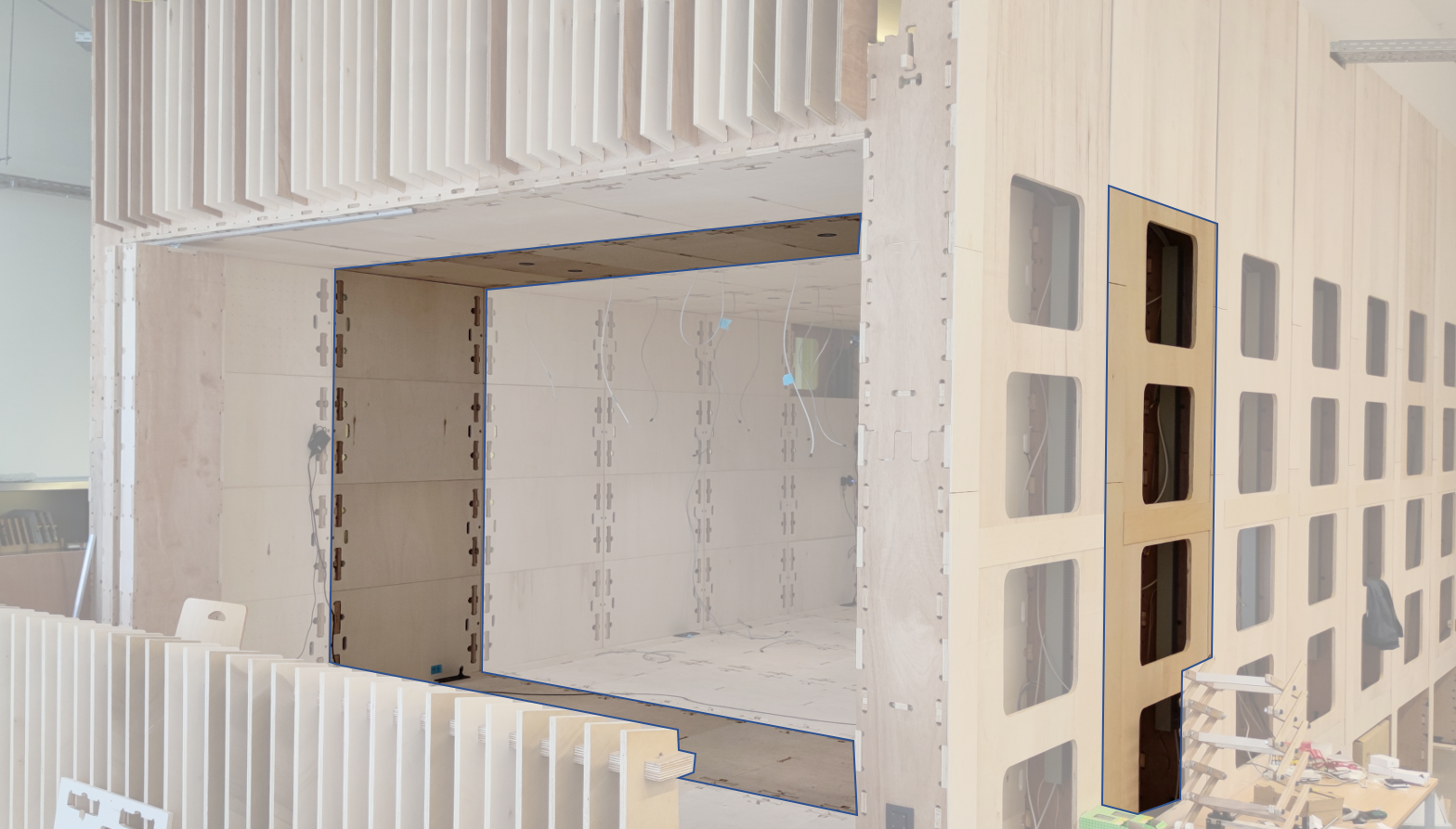
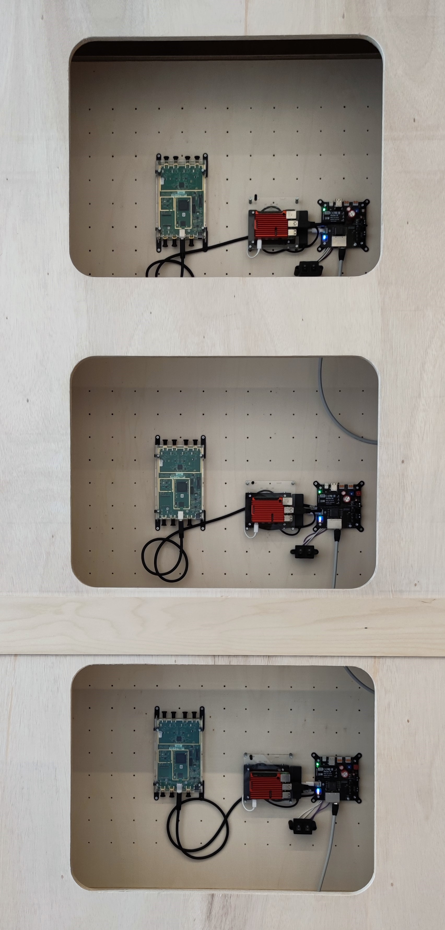
In [74, 57], the testbed has been used to evaluate communication performance in a realistic indoor office environment, see Fig. 7(a). The optical interconnects offer great flexibility in the placement of the CSPs, which makes the testbed particularly suitable for experimental evaluation of distributed versus co-located MIMO as discussed in Section II-B. In one of the testbed experiments, over-the-air channel information was collected and used to evaluate the multi-user MIMO capacity for a randomized location of four simultaneous users. As demonstrated from the results in Fig. 7(b), the D-MIMO (i.e., 6G) configuration offers much more uniform user capacity, compared to the co-located MIMO (i.e., 5G) case [57]. These results confirm the theoretical predictions in, e.g., [8].
Localization
The accurate phase coherence between different CSPs enables precise localization to be performed. In [75], the testbed was used to demonstrate a localization accuracy of below over an area of , in agreement with the theoretical bounds at most measurement locations. These results also validate the feasibility of D-MIMO for joint communication and localization applications.
III-C Millimeter-wave MIMO testbed (MATE)
When designing the MATE mmWave testbed, it was intended to be fabricated with COTS components, with the flexibility to replace those with our own designs. A main focus was research on calibration and the mitigation of hardware imperfections, in particular OTA. An intended application was MIMO communication, mainly MIMO links, but potentially also multiuser MIMO, for mmWaves. Radar signal processing was not a main goal, but a potential study topic. Another requirement was that it should be easily accessible for people that have not spent a lot of time in the lab environment. These requirements translated into a testbed that operates over the range , with analog bandwidth per transmitter or receiver. MATE supports up to 18 channels, which can be used in various configurations, with up to 16 transmitters and up to 9 receivers. The MATE baseband transmitter is implemented with digital-to-analog converters (DACs), FPGAs, sample clocks and triggering. To ensure the baseband signals are coherent, one sample clock is distributed to all DACs. The baseband receiver is similarly implemented, independent of the transmitter, with a single clock distributed to all analog-to-digital converters (ADCs), The baseband hardware (Fig. 8) consists of National Instruments PXIe chassis (NI PXIe-1085), reference clock/trigger modules (NI PXIe-6674T), DACs (Active Technologies AT-1212), ADCs (NI-5771) and FPGAs (PXIe-7975R). One or two embedded controllers (NI PXIe- 8880) control the system.
The testbed is controlled by a web interface, where a MATLAB client can be used to easily upload baseband data vectors to all antennas. These are up-converted to , transmitted over the TX antenna array, and received by the RX array. The receiver down-converts to baseband, and sends the data vectors back to MATLAB, over the web. The entire process takes about 8 seconds. Over time, many types of experiments have been performed using MATE. The large bandwidth enables research of a nature not available in most testbeds. To give a few examples, low-profile high-gain antennas were designed and manufactured [76] (Fig. 8). Calibration was studied in [73], and OTA calibration in [77]. Mitigation and modeling of hardware imperfections were studied in [78], and it was adapted to nonlinear distortion in [79]. Multi-user interference, and the effect on the signal quality, was studied in [80].
III-D Real-time mMIMO testbed: from centralized to distributed architecture
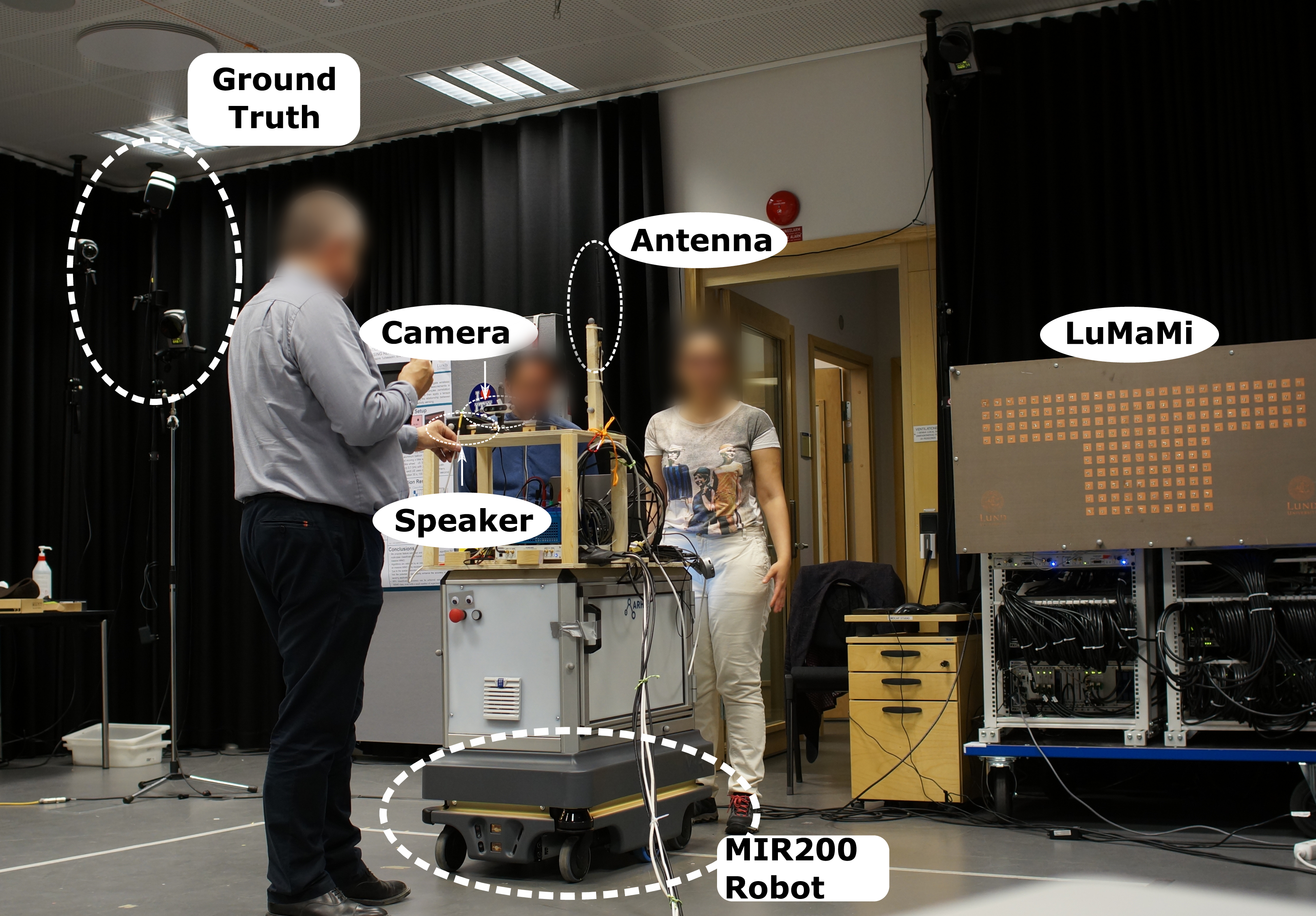
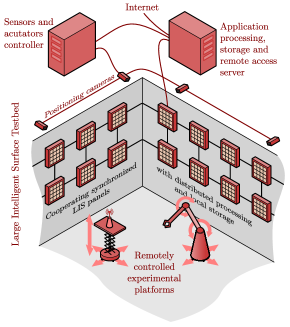
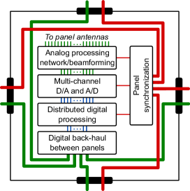
The LuMaMi testbed [29] at Lund University is a real-time OFDM-based mMIMO testbed, with 50 SDRs from NI, each with two TX and RX chains and Kintex-7 FPGAs, transmitting and receiving coherently and simultaneously on 100 antenna elements. The frequency range of the SDRs is , and the current setup is tailored for , with the centralized antenna array tuned to that frequency. With the FPGAs in the SDRs, together with four additional FPGAs for centralized processing, LuMaMi is capable of real-time operation of a 30.72 MS/s LTE-like air interface in TDD mode, with 1200 active subcarriers across a 20 MHz bandwidth. Due to the TDD-operation and reliance on reciprocity for channel knowledge and beamforming, the testbed also contains the necessary functionality for reciprocity calibration [81]. LuMaMi has been used in several different roles, testing the efficiency of spatial multiplexing [82], testing real-time processing in high mobility environments [83], and exploring mMIMO technology for new services in the band, as illustrated in Fig. 9 [71]. Because of the SDR flexibility, the testbed has also been used as a robust low-latency wireless link in cloud control of robots [84], a channel sounder in industrial environments [85], and for collecting audio/video/radio propagation data-sets for machine-learning based positioning services (illustrated in Fig. 10) [56]. Lund University is currently building on the experience with LuMaMi and is developing a distributed and modular testbed, where panels of 16-antenna arrays with localized processing capabilities are distributed in the environment, as illustrated in Fig. 11(a), and together operate coherently with a bandwidth of in the band. An overview of the internal architecture of the panels is shown in Fig. 11(b). The goal of this design is to further explore what can be achieved by exploiting spatial domain even further than what is done in traditional mMIMO. Based on RFSoC technology, the testbed is software controlled and supports real-time distributed processing, making it capable of both exploring many different service types, such as communication and positioning and also performing propagation measurements for the purpose of channel modeling, sensing and creation of datasets for machine-learning experiments.
IV Future directions
We identify two main future directions for 6G (and beyond) testbeds, and discuss these shortly below: the reduction of the complexity in the implementation of the first generation of 6G testbeds on the one hand, and extending their features and enabling the validation of new paradigms on the other hand.
IV-A Complexity reductions
The development of the first generation of 6G testbeds most importantly targets the functional possibility for validating new features and architectures of 6G technologies. In future upgrades, it should be a priority to achieve this with a low complexity implementation. By shifting away from dedicated systems and adopting low-cost COTS products, these systems can be established and deployed in more labs, becoming more accessible. This accessibility can act as a catalyst for advancing innovative ideas in 6G, ultimately leading to valuable technologies. Additionally, since these systems must accommodate large CSPs, the technologies, and hardware used must be scalable in terms of cost, hardware/software complexity, and energy consumption. Also, challenges encountered in the actual deployment of new wireless technologies often only fully reveal themselves in the creation of real-life testbeds. Moreover, solutions found and lessons learned from complexity and energy reductions in 6G testbeds may ’spill over’ to actual 6G deployments. The design of efficient implementations of testbeds may hence be an important fuel of innovation by itself.
IV-B Support for new features and paradigms
Superconvergence and co-created networks
The vision for 6G outlines a broad trend of superconvergence of and in networks. The evolution towards Multiple Radio Access Technology (Multi-RAT) support, in particular in combining solid connectivity in bqnds below with sub-THz wide bandwidth channels, is potentially in the foreseeable future the only answer to the question of offering at the same time a very high throughput and high reliability. A ’tandem’ operation, researched in the 6GTandem project (www.horizon-6gtandem.eu), bears the potential to offer the best of two worlds. The validation of network-of-networks, operating both in licensed and unlicensed bands, and comprising terrestrial and non-terrestrial components, comes with enormous complexity. This will require a joint approach involving both network simulators [86] and real-life testbeds. The new paradigm of networks that are co-created by citizens and to a large extent may result in bottom-up deployments, still opens a whole new dimension of freedom and potential chaos. The validation and optimization of these approaches also raise the need for new features to be supported in testbeds.
Millimeter-wave and sub-THz extensions
Another important future direction will be to extend current D-MIMO testbeds to mmWave and potentially sub-THz bands. [14] review the potential of mmWave D-MIMO and present an interesting testbed approach based on analog RoF [14]. In another recent work [27], a flexible SDoF link architecture, suitable for mmWave D-MIMO testbed applications, is presented.
V Conclusions
As diverse as the applications and technologies envisioned for sixth-generation (6G) networks, so too are the testbeds required to validate these technologies. This paper has introduced both different levels and various scopes for 6G testbeds. The article further focused on the main new capacity technology being distributed MIMO (D-MIMO). It has discussed approaches to address scaling and distributing the number of antennas and processing over the network, under more realistic conditions and in terms of hardware for studying real-life propagation situations and real-time behavior. Critical deployment challenges, such as the need to achieve synchronization in distributed architectures, are encountered in the development of these testbeds. These require solutions that may also bring great value in actual 6G deployments. Hence, this work highlights and details how D-MIMO 6G systems could be designed, implemented and deployed. The R&D towards 6G is far from finished, and so is the work to develop adequate testbeds. We have outlined directions to reduce complexity and enrich features in future developments.
Acknowledgments
References
- [1] EU H2020 REINDEER project “REsilient INteractive applications through hyper Diversity in Energy Efficient RadioWeaves technology (REINDEER) project - Deliverable 1.1: Use case-driven specifications and technical requirements and initial channel model”, 2021 URL: https://reindeer-project.eu/D1.1
- [2] Mikko A. Uusitalo et al. “6G Vision, Value, Use Cases and Technologies From European 6G Flagship Project Hexa-X” In IEEE Access 9, 2021, pp. 160004–160020 DOI: 10.1109/ACCESS.2021.3130030
- [3] Cheng-Xiang Wang et al. “On the Road to 6G: Visions, Requirements, Key Technologies and Testbeds” arXiv, 2023 DOI: 10.48550/ARXIV.2302.14536
- [4] Henk Wymeersch et al. “Integration of Communication and Sensing in 6G: a Joint Industrial and Academic Perspective” In 2021 IEEE 32nd Annual International Symposium on Personal, Indoor and Mobile Radio Communications (PIMRC), 2021, pp. 1–7 DOI: 10.1109/PIMRC50174.2021.9569364
- [5] Dusit Niyato, Dong In Kim, Marco Maso and Zhu Han “Wireless Powered Communication Networks: Research Directions and Technological Approaches” In IEEE Wireless Communications 24.6, 2017, pp. 88–97 DOI: 10.1109/MWC.2017.1600116
- [6] Ulf Gustavsson et al. “Implementation challenges and opportunities in beyond-5G and 6G communication” In IEEE Journal of Microwaves 1.1 IEEE, 2021, pp. 86–100
- [7] Yang Cao et al. “Experimental Performance Evaluation of Cell-free Massive MIMO Systems Using COTS RRU with OTA Reciprocity Calibration and Phase Synchronization” arXiv, 2022 DOI: 10.48550/ARXIV.2208.14048
- [8] Giovanni Interdonato et al. “Ubiquitous cell-free massive MIMO communications” In EURASIP Journal on Wireless Communications and Networking 2019 Springer, 2019, pp. 1–13
- [9] Jorge Morte Palacios, Orod Raeesi, Ahmet Gokceoglu and Mikko Valkama “Impact of Channel Non-Reciprocity in Cell-Free Massive MIMO” In IEEE Wireless Communications Letters 9.3, 2020, pp. 344–348
- [10] Gilles Callebaut, William Tärneberg, Liesbet Van der Perre and Emma Fitzgerald “Dynamic Federations for 6G Cell-Free Networking: Concepts and Terminology” In 2022 IEEE 23rd International Workshop on Signal Processing Advances in Wireless Communication (SPAWC), 2022, pp. 1–5 DOI: 10.1109/SPAWC51304.2022.9833918
- [11] Sara Gunnarsson et al. “mmWave Massive MIMO in Real Propagation Environment: Performance Evaluation Using LuMaMi28GHz” In 2021 55th Asilomar Conference on Signals, Systems, and Computers, pp. 80–84 IEEE
- [12] Peter B. Papazian et al. “A Radio Channel Sounder for Mobile Millimeter-Wave Communications: System Implementation and Measurement Assessment” In IEEE Transactions on Microwave Theory and Techniques 64.9, 2016, pp. 2924–2932 DOI: 10.1109/TMTT.2016.2592530
- [13] Jelena Senic et al. “Analysis of E-Band Path Loss and Propagation Mechanisms in the Indoor Environment” In IEEE Transactions on Antennas and Propagation 65.12, 2017, pp. 6562–6573 DOI: 10.1109/TAP.2017.2722876
- [14] Arno Moerman et al. “Beyond 5G Without Obstacles: mmWave-over-Fiber Distributed Antenna Systems” In IEEE Communications Magazine 60.1, 2022, pp. 27–33 DOI: 10.1109/MCOM.001.2100550
- [15] Jakob Hoydis, Fayçal Ait Aoudia, Alvaro Valcarce and Harish Viswanathan “Toward a 6G AI-Native Air Interface” In IEEE Communications Magazine 59.5, 2021, pp. 76–81 DOI: 10.1109/MCOM.001.2001187
- [16] Zijian Zhang et al. “Active RIS vs. Passive RIS: Which Will Prevail in 6G?” In IEEE Transactions on Communications 71.3, 2023, pp. 1707–1725 DOI: 10.1109/TCOMM.2022.3231893
- [17] Marco Giordani and Michele Zorzi “Non-Terrestrial Networks in the 6G Era: Challenges and Opportunities” In IEEE Network 35.2, 2021, pp. 244–251 DOI: 10.1109/MNET.011.2000493
- [18] Cheng-Xiang Wang et al. “Pervasive wireless channel modeling theory and applications to 6G GBSMs for all frequency bands and all scenarios” In IEEE Transactions on Vehicular Technology 71.9 IEEE, 2022, pp. 9159–9173
- [19] Min Zhu et al. “Ultra-wideband fiber-THz-fiber seamless integration communication system toward 6G: architecture, key techniques, and testbed implementation” In Science China Information Sciences 66.1 Springer, 2023, pp. 113301
- [20] Priyangshu Sen et al. “The TeraNova platform: An integrated testbed for ultra-broadband wireless communications at true Terahertz frequencies” In Computer Networks 179, 2020, pp. 107370 DOI: https://doi.org/10.1016/j.comnet.2020.107370
- [21] Tingjun Chen et al. “A Software-Defined Programmable Testbed for Beyond 5G Optical-Wireless Experimentation at City-Scale” In IEEE Network 36.2, 2022, pp. 90–99 DOI: 10.1109/MNET.006.2100605
- [22] Xenofon Foukas et al. “Experience Building a Prototype 5G Testbed” In Proceedings of the Workshop on Experimentation and Measurements in 5G, EM-5G’18 Heraklion, Greece: Association for Computing Machinery, 2018, pp. 13–18 DOI: 10.1145/3286680.3286683
- [23] Eduardo V.. Anjos et al. “FORMAT: A Reconfigurable Tile-Based Antenna Array System for 5G and 6G Millimeter-Wave Testbeds” In IEEE Systems Journal 16.3, 2022, pp. 4489–4500 DOI: 10.1109/JSYST.2022.3146360
- [24] Arjun Singh, Innem V.A.K. Reddy, Duschia Bodet and Josep M. Jornet “Bessel Beams for 6G - A Performance Analysis” In 2022 56th Asilomar Conference on Signals, Systems, and Computers, 2022, pp. 658–664 DOI: 10.1109/IEEECONF56349.2022.10052090
- [25] Simon Rommel et al. “Towards a scaleable 5G fronthaul: Analog radio-over-fiber and space division multiplexing” In Journal of Lightwave Technology 38.19 IEEE, 2020, pp. 5412–5422
- [26] Laurens Breyne et al. “Comparison between analog radio-over-fiber and sigma delta modulated radio-over-fiber” In IEEE Photonics Technology Letters 29.21 IEEE, 2017, pp. 1808–1811
- [27] Husileng Bao, Filippo Ponzini and Christian Fager “Flexible Mm-Wave Sigma-Delta-Over-Fiber MIMO Link” In Journal of Lightwave Technology IEEE, 2023, pp. 1–10 DOI: 10.1109/JLT.2023.3248147
- [28] Martina Truskaller et al. “Use case-driven specifications and technical requirements and initial channel model”, 2021
- [29] S. Malkowsky et al. “The World’s First Real-Time Testbed for Massive MIMO: Design, Implementation, and Validation” In IEEE Access 5, 2017, pp. 9073–9088 DOI: 10.1109/ACCESS.2017.2705561
- [30] Jesús Rodrı́guez Sánchez et al. “Decentralized massive MIMO processing exploring daisy-chain architecture and recursive algorithms” In IEEE Transactions on Signal Processing 68 IEEE, 2020, pp. 687–700
- [31] Jesús Rodrı́guez Sánchez, Fredrik Rusek, Ove Edfors and Liang Liu “Distributed and Scalable Uplink Processing for LIS: Algorithm, Architecture, and Design Trade-Offs” In IEEE Transactions on Signal Processing 70 IEEE, 2022, pp. 2639–2653
- [32] Dongming Wang et al. “Implementation of a Cloud-Based Cell-Free Distributed Massive MIMO System” In IEEE Communications Magazine 58.8, 2020, pp. 61–67 DOI: 10.1109/MCOM.001.2000106
- [33] “Techtile–open 6g r&d testbed for communication, positioning, sensing, wpt and federated learning”
- [34] Joe Breen et al. “POWDER: Platform for Open Wireless Data-driven Experimental Research” In Proceedings of the 14th International Workshop on Wireless Network Testbeds, Experimental Evaluation and Characterization (WiNTECH), 2020 DOI: 10.1145/3411276.3412204
- [35] Mi Hyun Lee et al. “Demo: SDR Implementation of a Fully Distributed Cell-Free MIMO System” In 2022 IEEE International Conference on Communications Workshops (ICC Workshops), 2022, pp. 1–2 DOI: 10.1109/ICCWorkshops53468.2022.9915020
- [36] Yang Cao et al. “From ORAN to Cell-Free RAN: Architecture, Performance Analysis, Testbeds and Trials” arXiv, 2023 DOI: 10.48550/ARXIV.2301.12804
- [37] Muhammad M Rahman, Henry E Baidoo-Williams, Raghuraman Mudumbai and Soura Dasgupta “Fully wireless implementation of distributed beamforming on a software-defined radio platform” In Proceedings of the 11th international conference on Information Processing in Sensor Networks, 2012, pp. 305–316
- [38] Ryan Rogalin et al. “Scalable synchronization and reciprocity calibration for distributed multiuser MIMO” In IEEE transactions on wireless communications 13.4, 2014, pp. 1815–1831
- [39] Horia Vlad Balan et al. “AirSync: Enabling distributed multiuser MIMO with full spatial multiplexing” In IEEE/ACM Transactions on Networking 21.6, 2013, pp. 1681–1695
- [40] M M Rahman, S Dasgupta and R Mudumbai “A distributed consensus approach to synchronization of RF signals” In IEEE Statistical Signal Processing Workshop IEEE, 2012, pp. 281–284
- [41] Luis M. Pessoa, Joana S. Tavares, Diogo Coelho and Henrique M. Salgado “Experimental evaluation of a digitized fiber-wireless system employing sigma delta modulation” In Optics Express 22.14 The Optical Society, 2014, pp. 17508–17523
- [42] Chia-Yi Wu et al. “Distributed multi-user MIMO transmission using real-time sigma-delta-over-fiber for next generation fronthaul interface” In Journal of Lightwave Technology 38.4 IEEE, 2019, pp. 705–713
- [43] Ibrahim Can Sezgin et al. “A Low-Complexity Distributed-MIMO Testbed Based on High-Speed Sigma–Delta-Over-Fiber” In IEEE Transactions on Microwave Theory and Techniques 67.7 IEEE, 2019, pp. 2861–2872
- [44] A. Bourdoux, B. Come and N. Khaled “Non-reciprocal transceivers in OFDM/SDMA systems: Impact and mitigation” In Proceedings - 2003 IEEE Radio and Wireless Conference, RAWCON 2003 Institute of ElectricalElectronics Engineers Inc., 2003, pp. 183–186
- [45] Florian Kaltenberger, Haiyong Jiang, Maxime Guillaud and Raymond Knopp “Relative channel reciprocity calibration in MIMO/TDD systems” In 2010 Future Network and Mobile Summit IEEE, 2010, pp. 1–10
- [46] Clayton Shepard et al. “Argos: Practical many-antenna base stations” In Proceedings of the Annual International Conference on Mobile Computing and Networking, MOBICOM New York, New York, USA: ACM Press, 2012, pp. 53–64
- [47] Joao Vieira, Fredrik Rusek and Fredrik Tufvesson “Reciprocity calibration methods for massive MIMO based on antenna coupling” In 2014 IEEE Global Communications Conference, GLOBECOM 2014 Institute of ElectricalElectronics Engineers Inc., 2014, pp. 3708–3712
- [48] R. Braithwaite “Digital Predistortion of a RF Power Amplifier using a Remote Closed Loop Estimator” In 2020 IEEE Topical Conference on RF/Microwave Power Amplifiers for Radio and Wireless Applications, PAWR 2020 Institute of ElectricalElectronics Engineers Inc., 2020, pp. 42–45
- [49] Raghuraman Mudumbai, D. Brown, Upamanyu Madhow and H. Poor “Distributed Transmit Beamforming : Challenges and Recent Progress” In IEEE Communications Magazine 47.2 IEEE, 2009, pp. 102–110
- [50] Ali A Nasir et al. “REVIEW Open Access Timing and carrier synchronization in wireless communication systems: a survey and classification of research in the last 5 years” In EURASIP Journal on Wireless Communications and Networking 2016, 2016, pp. 180
- [51] Thomas Bigler, Albert Treytl, David Loschenbrand and Thomas Zemen “High Accuracy Synchronization for Distributed Massive MIMO using White Rabbit” In IEEE International Symposium on Precision Clock Synchronization for Measurement, Control, and Communication, ISPCS 2018-September IEEE Computer Society, 2018
- [52] François Quitin, Upamanyu Madhow, Muhammad Mahboob Ur Rahman and Raghuraman Mudumbai “Demonstrating distributed transmit beamforming with software-defined radios” In IEEE International Symposium on a World of Wireless, Mobile and Multimedia Networks (WoWMoM), 2012, pp. 1–3
- [53] Simon Schmitt et al. “A reference system for indoor localization testbeds” In 2012 International Conference on Indoor Positioning and Indoor Navigation (IPIN), 2012, pp. 1–8 DOI: 10.1109/IPIN.2012.6418865
- [54] Ahmed Alkhateeb et al. “DeepSense 6G: A large-scale real-world multi-modal sensing and communication dataset” In arXiv preprint arXiv:2211.09769 arXiv, 2022 DOI: 10.48550/ARXIV.2211.09769
- [55] D. Johnson et al. “Mobile Emulab: A Robotic Wireless and Sensor Network Testbed” In Proceedings IEEE INFOCOM 2006. 25TH IEEE International Conference on Computer Communications, 2006, pp. 1–12 DOI: 10.1109/INFOCOM.2006.182
- [56] Ilayda Yaman et al. “The LuViRA Dataset: Measurement Description” arXiv, 2023 DOI: 10.48550/ARXIV.2302.05309
- [57] Husileng Bao et al. “Automatic Distributed MIMO Testbed for Beyond 5G Communication Experiments” In 2021 IEEE MTT-S International Microwave Symposium (IMS), 2021, pp. 697–700 DOI: 10.1109/IMS19712.2021.9574865
- [58] Seppo Horsmanheimo et al. “Indoor Positioning Platform to Support 5G Location Based Services” In 2019 IEEE International Conference on Communications Workshops (ICC Workshops), 2019, pp. 1–6 DOI: 10.1109/ICCW.2019.8757118
- [59] Jorge Gomez Ponce et al. “Air-to-Ground Directional Channel Sounder With 64-antenna Dual-polarized Cylindrical Array” arXiv, 2021 DOI: 10.48550/ARXIV.2103.09135
- [60] Thomas Choi et al. “Using a Drone Sounder to Measure Channels for Cell-Free Massive MIMO Systems” In 2022 IEEE Wireless Communications and Networking Conference (WCNC) Austin, TX, USA: IEEE Press, 2022, pp. 2506–2511 DOI: 10.1109/WCNC51071.2022.9771649
- [61] Gouranga Charan, Muhammad Alrabeiah and Ahmed Alkhateeb “Vision-aided 6G wireless communications: Blockage prediction and proactive handoff” In IEEE Transactions on Vehicular Technology 70.10 IEEE, 2021, pp. 10193–10208
- [62] Pratheek S. Upadhyaya et al. “Prototyping Next-Generation O-RAN Research Testbeds with SDRs” In arXiv preprint arXiv:2205.13178 arXiv, 2022 DOI: 10.48550/ARXIV.2205.13178
- [63] Navid Nikaein et al. “OpenAirInterface: A flexible platform for 5G research” In ACM SIGCOMM Computer Communication Review 44.5 ACM New York, NY, USA, 2014, pp. 33–38
- [64] Jian Ding, Rahman Doost-Mohammady, Anuj Kalia and Lin Zhong “Agora: Real-Time Massive MIMO Baseband Processing in Software” In Proceedings of the 16th International Conference on Emerging Networking EXperiments and Technologies, CoNEXT ’20 Barcelona, Spain: Association for Computing Machinery, 2020, pp. 232–244 DOI: 10.1145/3386367.3431296
- [65] Renjie Zhao et al. “M-cube: A millimeter-wave massive MIMO software radio” In Proceedings of the 26th Annual International Conference on Mobile Computing and Networking, 2020, pp. 1–14
- [66] Mark D Wilkinson et al. “The FAIR Guiding Principles for scientific data management and stewardship” In Scientific data 3.1 Nature Publishing Group, 2016, pp. 1–9
- [67] Rice University “Renew software git repository”, https://github.com/renew-wireless/RENEWLab, 2023
- [68] Dipankar Raychaudhuri et al. “Challenge: COSMOS: A city-scale programmable testbed for experimentation with advanced wireless” In Proceedings of the 26th Annual International Conference on Mobile Computing and Networking, 2020, pp. 1–13
- [69] Ahmed Alkhateeb “DeepMIMO: A Generic Deep Learning Dataset for Millimeter Wave and Massive MIMO Applications” In CoRR abs/1902.06435, 2019 arXiv: http://arxiv.org/abs/1902.06435
- [70] M. Alrabeiah, A. Hredzak, Z. Liu and A. Alkhateeb “ViWi: A Deep Learning Dataset Framework for Vision-Aided Wireless Communications” In submitted to IEEE Vehicular Technology Conference, 2019
- [71] MinKeun Chung et al. “LuMaMi28: Real-Time Millimeter-Wave Multi-User MIMO Systems with Antenna Selection” In IEEE Transactions on Wireless Communications, 2023, pp. 1–1 DOI: 10.1109/TWC.2023.3257195
- [72] Cheng-Ming Chen et al. “Distributed Massive MIMO: A Diversity Combining Method for TDD Reciprocity Calibration” In GLOBECOM 2017 - 2017 IEEE Global Communications Conference, 2017, pp. 1–7 DOI: 10.1109/GLOCOM.2017.8254817
- [73] Koen Buisman and Thomas Eriksson “Designing and characterizing MATE, the Chalmers mm-wave MIMO testbed” In EuCAP, 2018, pp. 388–392
- [74] Christian Fager et al. “Comparison of Co-located and Distributed MIMO for Indoor Wireless Communication” In 2022 IEEE Radio and Wireless Symposium (RWS), 2022, pp. 83–85 DOI: 10.1109/RWS53089.2022.9719879
- [75] Musa Furkan Keskin et al. “Localization With Distributed MIMO Using a High-Speed Sigma-Delta-Over-Fiber Testbed” In IEEE Microwave and wireless components letters 32.7 IEEE, 2022, pp. 923–926
- [76] Lei Shi et al. “High-Efficiency and Wideband Aperiodic Array of Uniformly Excited Slotted Waveguide Antennas Designed Through Compressive Sensing” In IEEE Transactions on Antennas and Propagation 67.5 IEEE, 2019, pp. 2992–2999
- [77] Koen Buisman and Thomas Eriksson “MIMO mmWave Over-the-air Testbed Calibration using Symmetries and Experimental Verification” In 2022 16th European Conference on Antennas and Propagation, EuCAP 2022 European Association for AntennasPropagation, 2022
- [78] Sina Rezaei Aghdam, Mohammad Hossein Moghaddam, Koen Buisman and Thomas Eriksson “Compensation of Hardware Impairments in MATE, the Chalmers mmWave MIMO Testbed”, 2018
- [79] Hamza Nachouane, Thomas Eriksson and Koen Buisman “Nonlinear Distortion Investigation Using mm-Wave Over-the-Air SISO and MISO Measurements” In EuCAP, 2021
- [80] Koen Buisman et al. “Millimeter-Wave Over-the-Air Signal-to-Interference-plus-Noise-Ratio Measurements Using a MIMO Testbed” In AT-RASC, 2018
- [81] Joao Vieira et al. “Reciprocity Calibration for Massive MIMO: Proposal, Modeling, and Validation” In IEEE Transactions on Wireless Communications 16.5, 2017, pp. 3042–3056 DOI: 10.1109/TWC.2017.2674659
- [82] Amy Nordrum “5G Researchers Set New World Record For Spectrum Efficiency”, 2016 IEEE Spectrum URL: https://spectrum.ieee.org/5g-researchers-achieve-new-spectrum-efficiency-record
- [83] P. Harris et al. “Performance Characterization of a Real-Time Massive MIMO System With LOS Mobile Channels” In IEEE Journal on Selected Areas in Communications 35.6, 2017, pp. 1244–1253 DOI: 10.1109/JSAC.2017.2686678
- [84] P. Skarin, W. Tärneberg, Karl-Erik Årzen and M. Kihl “Towards mission-critical control at the edge and over 5G” In 2018 IEEE international conference on edge computing (EDGE), 2018, pp. 50–57 IEEE
- [85] Sara Gunnarsson et al. “REPORT ON 5G RADIO DEPLOYABILITY IN THE FACTORY”, 2022 URL: https://5gsmart.eu/wp-content/uploads/5G-SMART-D4.2-v2.0.pdf
- [86] Francesc Wilhelmi et al. “Usage of Network Simulators in Machine-Learning-Assisted 5G/6G Networks” In IEEE Wireless Communications 28.1, 2021, pp. 160–166 DOI: 10.1109/MWC.001.2000206