Observation of a Brillouin dynamic grating in silicon nitride waveguides
Abstract
Brillouin enhanced four wave mixing in the form of a Brillouin dynamic grating (BDG) enables a uniquely tunable filter, whose properties can be tuned by purely optical means. This makes the BDG a valuable tool in microwave photonics (MWP). BDGs have been studied extensively in fibers, but the only observation in an integrated platform required exotic materials. Unlocking BDG in a standard and mature platform will enable its integration into large-scale circuits. Here we demonstrate the first observation of a BDG in a silicon nitride (Si3N4) waveguide. We also present a new, optimized design, which will enhance the BDG response of the waveguide, unlocking a path to large-scale integration into MWP circuits.
Introduction
Optomechanical interactions have been gaining interest as a research topic recently Aspelmeyer_RevModPhys_2014 ; Safavi_Opt_2019 ; Eggleton_NatPhot_2019 , showing promising applications in many fields such as telecommunication Li_NatComm_2013 ; Marpaung_Optica_2015 , quantum technologies Barzanjeh_NatPhys_2022 , high resolution spectrometers Dong_OL_2014 and sensing Kim_JLT_2015 ; Li_Opt_2017 ; Li_Optica_2018 .
A Brillouin dynamic grating (BDG) introduces enhanced flexibility into optomechanics. This grating is unique because it can be tuned in both strength and bandwidth via purely optical means. Furthermore, the probe light is orthogonally polarized from the pumps, so a polarization beam splitter can be used to combine and split the signals. BDG has shown promising applications in microwave photonics (MWP) such as variable time delays Chin_LPR_2012 ; Merklein_JoO_2018 , multi-tap filters Sancho_OE_2012 and true-time reversal Santagiustina_SciRep_2013 .
BDGs have first been demonstrated in polarization maintaining fiber Song_OL_2008 , and later also in single-mode Song_OL_2011 and few-mode fibers Li_OL_2012 . However the only on-chip observation so far has been in a chalcogenide, As2S3, based waveguide Pant_OL_2013 . Although this material is a great host for Brillouin scattering, its integrability is limited, leading to a reduced potential for use in large-scale circuits.
In this work, we show for the first time the observation of a BDG in a standard, low-loss silicon nitride (Si3N4) waveguide. We build on our recent work where we showed guided-acoustic Brillouin scattering in the multilayer silicon nitride platform, leading to record-high Brillouin gain coefficients in Si3N4 waveguides Botter_SciAdv_2022 . This is a substantial advancement in the application of Brillouin dynamic gratings in microwave photoncs, as it unlocks the process in a mature photonics platform that has a large library of MWP components, in which we have recently shown record-high performance Roeloffzen_JSTQE_2018 ; Daulay_NatComm_2022 ; Liu_APLPhot_2023 .
Operating principle
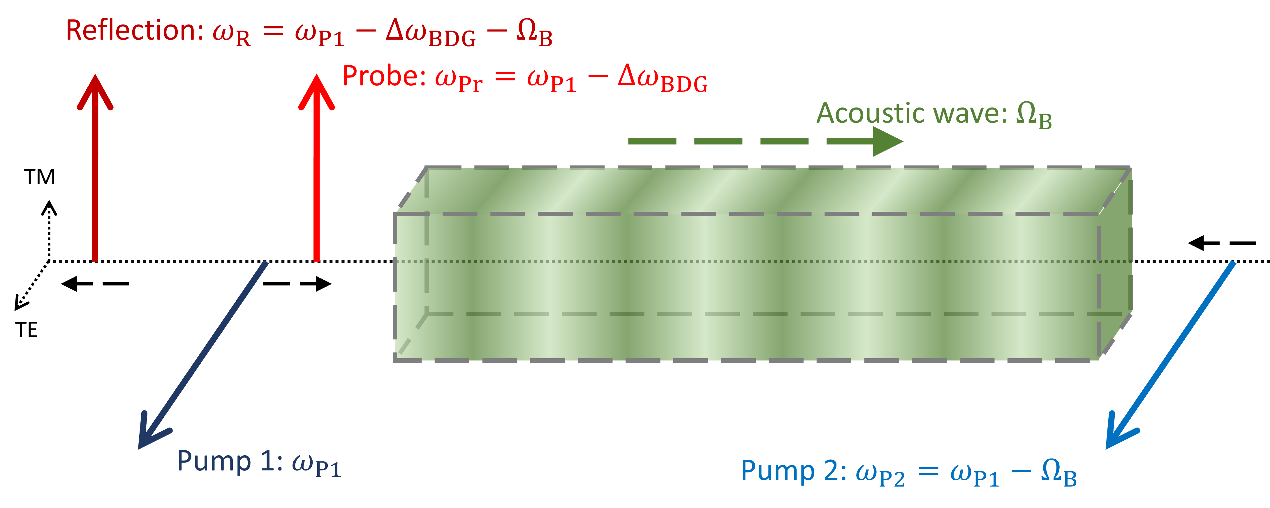
The creation and probing of Brillouin dynamic gratings is a four wave mixing process that is supported by stimulated Brillouin scattering (SBS), and therefore represents a form of Brillouin enhanced four wave mixing Bergman_Sensors_2018 . A schematic depiction of the process can be seen in Fig. 1. In essence a BDG is an extension of the SBS process with an additional probe wave.
In SBS a probe wave interacts with a counter-propagating higher power pump wave, which is detuned with a frequency on the order of 10 GHz. If the detuning of these two waves matches the Brillouin frequency of the waveguide, , the interference between these two waves creates a sound wave through electrostriction. The frequency of this sound wave is equal to the Brillouin frequency. Via the photoelastic effect this sound wave then creates a moving Bragg-like grating. This grating will reflect the pump light, which is then Doppler shifted due to the motion of the acoustic grating. The reflected pump light will then match the frequency of the probe, resulting in a amplification with a typical bandwidth on the order of 10 – 100 MHz Boyd_Book_2008 ; Agrawal_Book_2013 .
For the extension of the SBS process into the generation of a BDG, the probe wave is replaced by a second pump, as depicted in Fig. 1. Both pumps are in the transverse electric (TE) polarization, and generate an acoustic wave as described above. An new probe wave, transverse magnetic (TM) polarized and therefore orthogonal to the two pumps, is then introduced, co-propagating with the higher-power, higher-frequency pump 1. This probe wave is then used to characterize the grating created by the acoustic wave. When the probe light has the right wavelength, it will be reflected by the grating, undergoing a Doppler shift equal to the Brillouin frequency .
Light will only be reflected by the Bragg-like acoustic grating if the wavelength in the waveguide matches the grating period. In the waveguide the wavelength of pump 1 is
| (1) |
and the wavelength of the probe is
| (2) |
Here and are the pump 1 and probe vacuum wavelengths respectively, and and are the effective refractive indices of the TE and TM mode of the waveguide.
In the SBS process between the two pumps, pump 1 is reflected by the acoustic grating. This means that the wavelength of pump 1 is in the reflection band of the grating, and for the probe wavelength to reflect it should be the same. Using this we can calculate the required probe wavelength:
| (3) | ||||
| (4) | ||||
| (5) |
This equation shows one of the advantages of a BDG, compared to the regular Brillouin process. In a BDG the frequency separation of pumps and probe, , can be up to tens of nanometers, depending on the birefringence of a waveguide, which is much larger than the 10 GHz typically seen in SBS. This makes it easier to remove the pump light from the signal path, which reduces noise that can be introduced by the high power of the pump waves. Furthermore, the difference in polarization enables an extra filtering step for separating pump and probe with the use of a polarizer or a polarization beam splitter, strengthening this effect.
The biggest advantage of a BDG is its unique dynamic nature. Assuming the grating is weak, which means the refractive index variation is small, the bandwidth of a BDG is determined by Dong_OE_2010
| (6) |
where is the speed of light, and the grating length. The length of the grating can be tuned by pulsing the pump waves, as the acoustic wave is only generated where the pump waves overlap. This way the bandwidth of the grating can be wider or narrower by making the grating shorter or longer. Furthermore, the time delay between the input probe and reflection can also be tuned by changing the location where the pump pulses meet and overlap, thus the location of the grating. These two dynamically tunable parameters of the grating response make the BDG a uniquely agile filter.
Waveguide properties
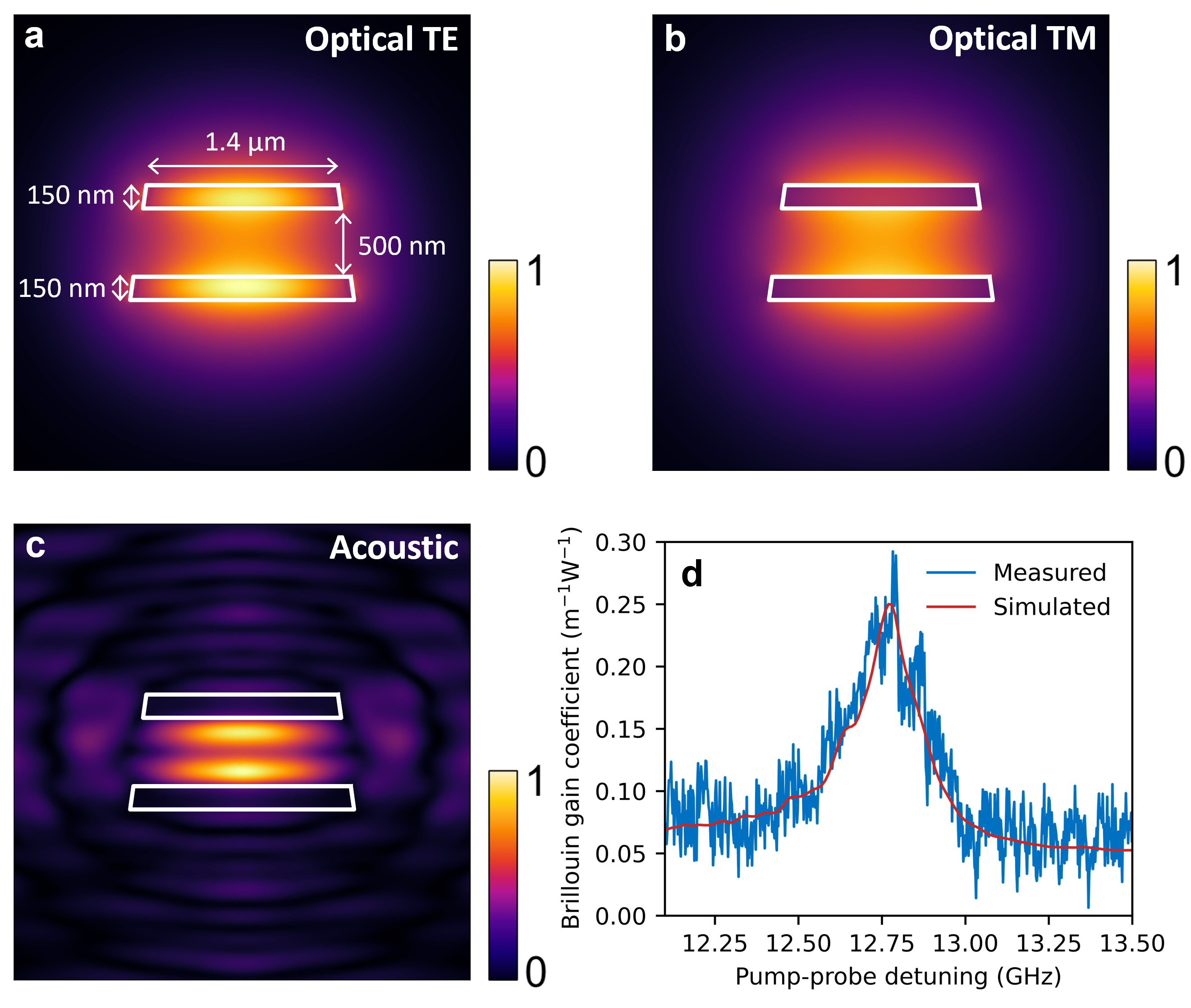
In this research we used silicon nitride waveguides. They are made using the symmetric double stripe (SDS) geometry as shown in Fig. 2a, which consists of two silicon nitride (Si3N4) layers which are both 150 nm high, and separated by a 500 nm layer of silicon oxide (SiO2) Botter_SciAdv_2022 ; Roeloffzen_JSTQE_2018 . A selection of widths is available in our samples, these are listed in Table 1, along with their properties. These waveguides have been optimized for single-mode use of the TE00 mode, with low-loss chip-to-fiber coupling and the lowest bending radius that does not increase the propagation losses. The TM mode is not confined as much as the TE mode, which is reflected in the lower TM refractive indices. As a result the losses in the chip-to-fiber coupling and in the bends is significantly higher.
| (µm) | [TE] | [TM] | (nm) | (m-1W-1) | (dB/cm) |
| 1.1 | 1.528 | 1.482 | 1509 | 0.20 | 0.228 |
| 1.2 | 1.534 | 1.485 | 1506 | 0.24 | 0.223 |
| 1.4 | 1.543 | 1.490 | 1502 | 0.25 | 0.206 |
| 1.5 | 1.547 | 1.492 | 1501 | 0.25 | 0.230 |
| 3.0 | 1.574 | 1.509 | 1492 | 0.40 | 0.195 |
To maximise the observable signal we want to use a waveguide that has a high Brillouin gain and low (TE) propagation losses, and the birefringence should not be too high, as our probe laser has a lower wavelength limit of about 1500 nm. Based on these criteria and the data from Table 1 we selected the 1.4 µm wide waveguide, which has the highest Brillouin gain coefficient and propagation loss for the waveguides with a simulated probe wavelength of more than 1500 nm.
In this work we used an SDS waveguide with a length of 50 cm, folded in a quasi-rectangular spiral. The wavelength of the pump laser is around 1556 nm, which in the TE mode corresponds to an effective index of 1.543, with a mode field as shown in Fig. 2a. The corresponding probe wavelength calculated combining Eq. 5 with mode simulations in Optodesigner is 1502 nm, with an effective TM index of 1.490, shown in Fig. 2b. In this waveguide the TE mode has a Brillouin gain of 0.25 m-1W-1 with a shift of 12.76 GHz, a propagation loss of 0.206 dB/cm and a coupling loss of 1.3 dB/facet Botter_SciAdv_2022 . The acoustic mode at the peak Brillouin shift is depicted in Fig. 2c. Simulations show that for the TM mode the fiber-chip coupling losses are about 6.5 dB/facet, and the tight bends (radius 100 µm) will have losses of 82 dB/cm, which corresponds to 1.2 dB per 90° bend. As a result, the TM mode will not propagate far into the waveguide, leading to a low reflection, and a weak BDG signal.
The high TM losses do lead to a shorter effective grating length, and as a result a larger bandwidth. According to Eq. (6) the bandwidth is 1.2 GHz if it is present in the full 50 cm length of our waveguide spiral. However, if we assume only the 1 cm of waveguide between the facet and the first bend contributes, the bandwidth is 61 GHz. This is a slight overestimation, but it shows that the observation will be easier, as the probe laser can be scanned with larger steps.
Experimental setup
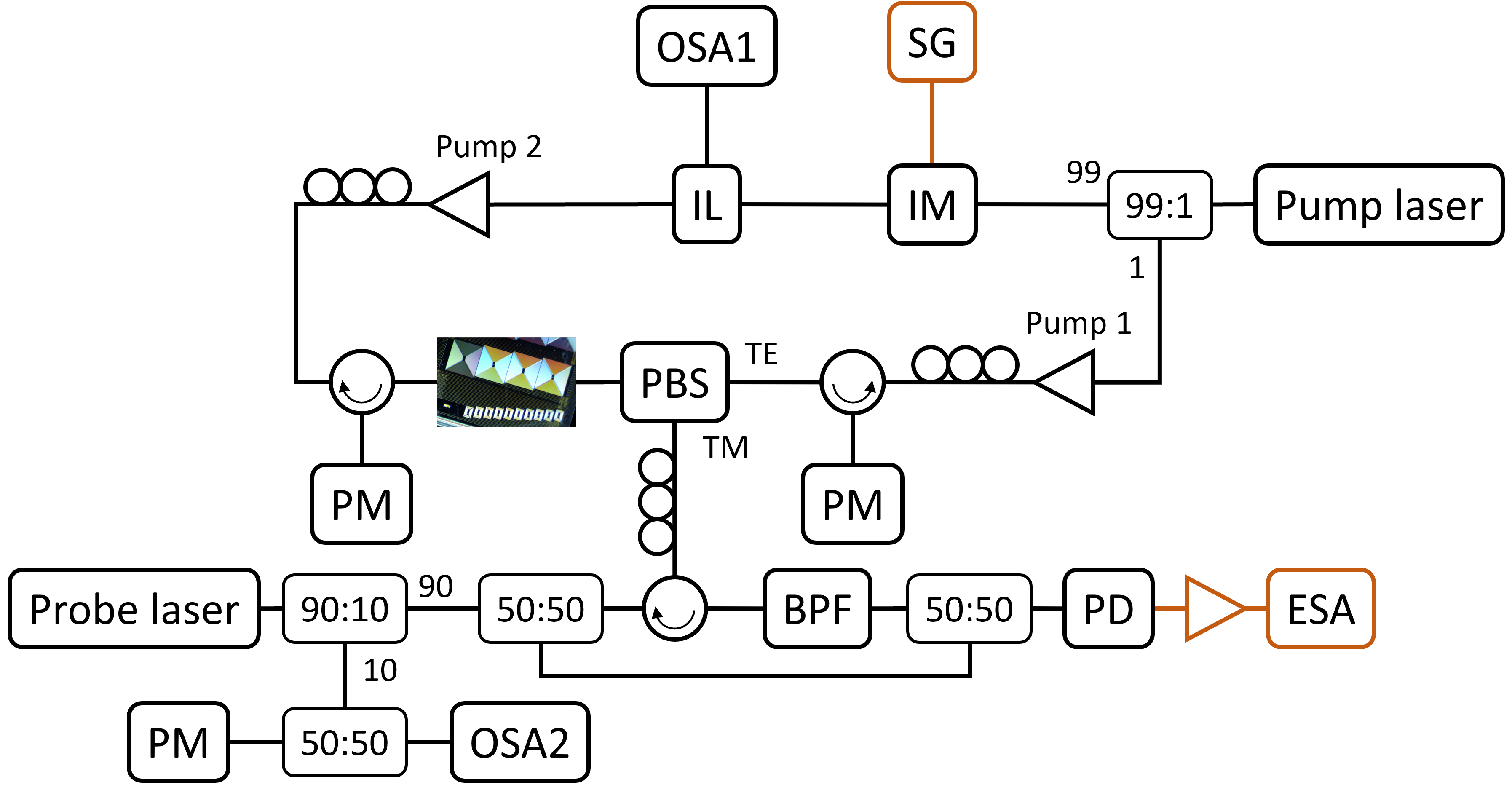
Fig. 3 shows the setup used in this experiment. For mutual frequency stability the two pump waves are derived from the same laser source, an APIC Ultra Low Noise Laser. The laser output is split using a 99:1 splitter to create the two pump lines. This laser is set to 1555.82 nm, to match the pump wavelengths with the interleaver response.
The 99% arm is modulated using a Thorlabs LNA6213 intensity modulator, connected to a Wiltron 69147A signal generator set to 12.76 GHz, the Brillouin shift frequency of the waveguide. The lower sideband is then selected using an Optoplex IL-CTBFAC687 interleaver, and amplified to 21.4 dBm using an Amonics AEDFA-PA-35-B-FA, creating pump 2. The upper sideband and carrier are sent to a Finisar 1500s optical spectrum analyser (labelled OSA1 in Fig. 3) to determine the pump frequencies. The measured spectrum is shown in Fig. 4b.
The 1% arm of the splitter is ampilified using an Amonics AEDFA-33-B-FA to 33.8 dBm, and serves as pump 1.
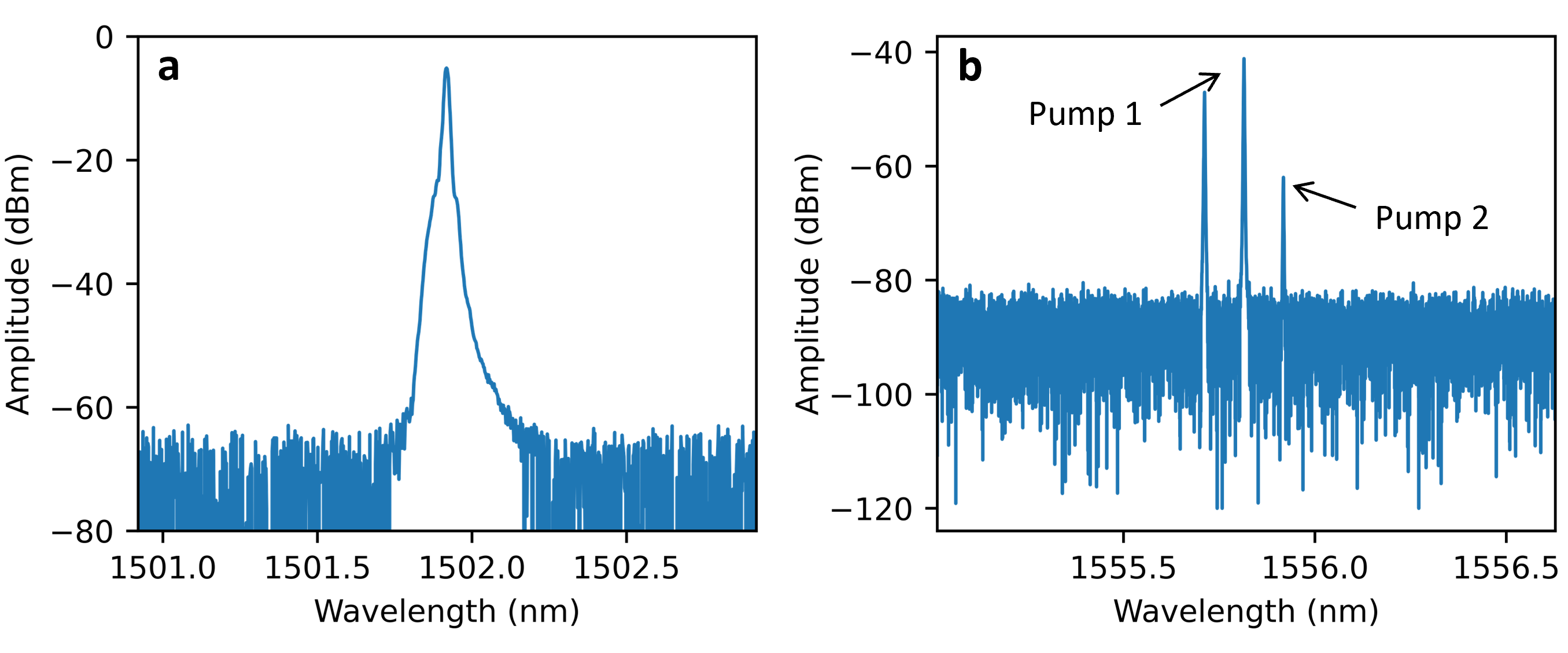
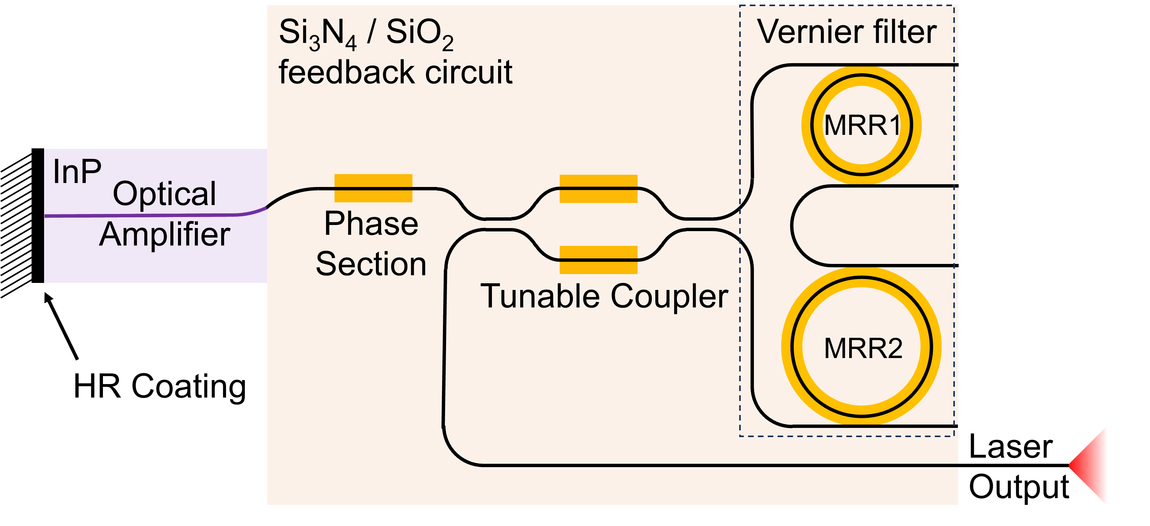
To reach the required probe wavelength we use a hybrid integrated laser, consisting of an indium phosphide gain section and a silicon nitride feedback circuit, as depicted in Fig. 5 Oldenbeuving_LPL_2013 ; Fan_IEEEPhot_2016 ; VanRees_OE_2020 . This Vernier filter of this laster is designed a tuning range of 120 nm around 1540 nm. This laser is tuned to the BDG frequency, outputting 8.59 dBm. 10% of the light is split off to a power meter and an Ando AQ6317 optical spectrum analyzer to measure the wavelength, shown in Fig. 4a. The other 90% of light of this laser is split 50:50, with one half acting as the probe, and the other half used for the heterodyne detection of the BDG reflection.
The probe light (in the TM mode) is combined with the light of pump 1 (in the TE mode) using a polarization beam splitter (PBS). This light is then sent into the chip. Pump 2 is sent to the waveguide from the other direction, also in the TE mode.
Part of the probe light is reflected in the BDG process. This reflected light is filtered from the pumps via the PBS and split off via a circulator. The signal is then further filtered using an EXFO XTM-50-SCL-U tunable bandpass filter, to block any pump light that has passed the PBS. The reflected light is then combined with the probe light for heterodyne detection on a Discovery Semiconductor DSC30S photodiode. This signal is amplified with a Mini-Circuits ZVA-213-S+ gain block. The RF signal is then analyzed using a Keysight N9000B electrical spectrum analyser (ESA).
Results
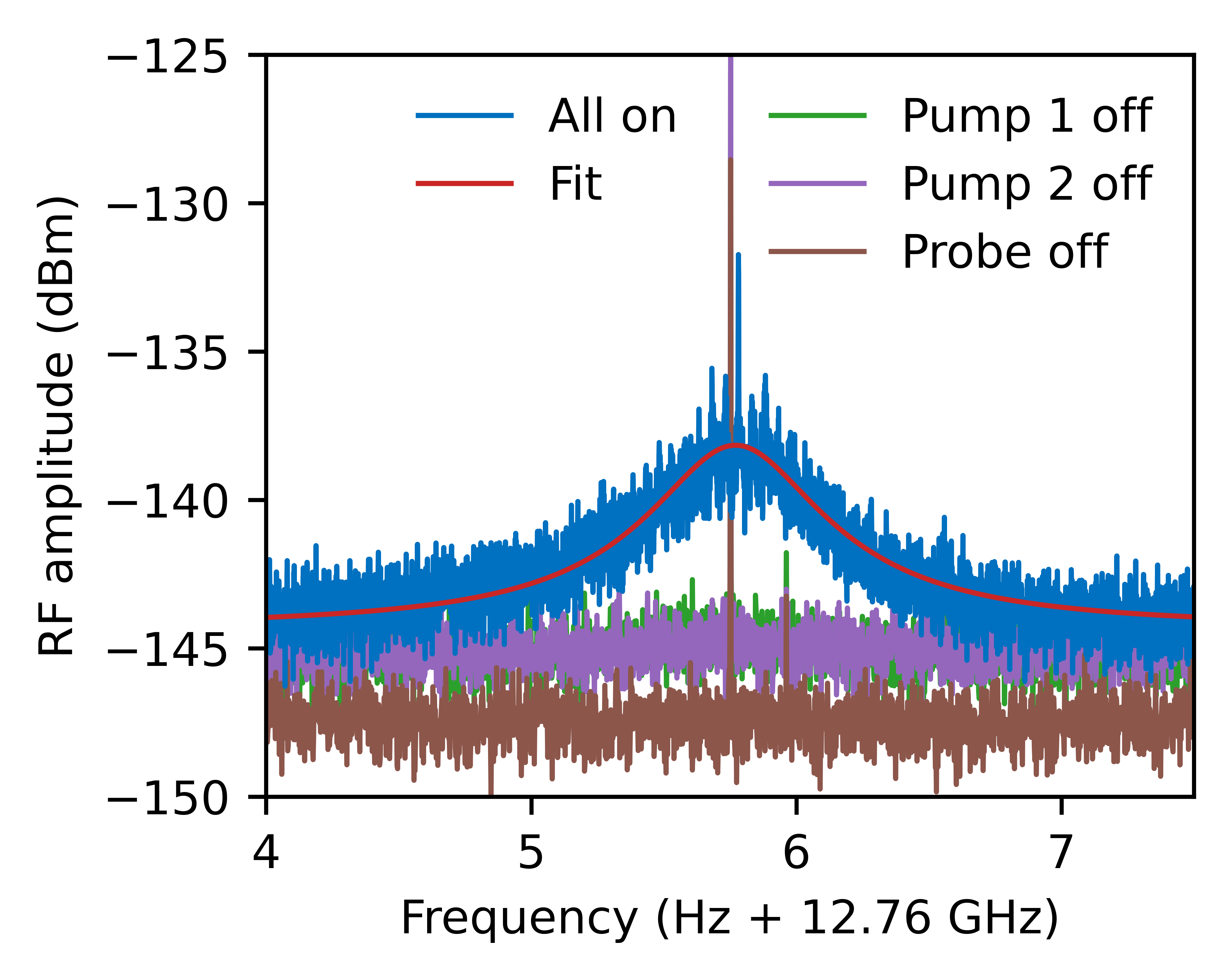
After scanning the probe laser around 1502 nm we found a response when the probe was at 1501.92 nm, as can be seen in Fig. 6. To verify that the peak is the result of a BDG interaction, we repeated the measurement with each time one of the three light sources turned off. In each of these cases there was no signal present, as depicted in Fig. 6. A second verification step was to change the probe wavelength by more than 61 GHz, our largest estimate of the BDG bandwidth. As expected, the signal was also not present when the probe wavelength was tuned to 1502.48 nm, as shown in Fig. 7.
The peak is not exactly at 12.76 GHz due to a small frequency offset between the signal generator and the ESA. The measurement shows one large spike due to interference from the signal generator to the spectrum analyser. A Lorentzian fit using the Python package lmfit is overlayed, showing a full width at half maximum of 603 Hz.

From the fit in Fig. 6 we can see that the recorded signal has an RF power of -138.1 dBm. The gain block has an amplification of 26 dB, meaning that the actual RF signal is at -164.1 dBm.
The photodiode generates a photocurrent due to the incoming optical field equal to
| (7) |
Where is the responsivity of the photodiode, in this case 0.8 A/W. The resulting RF power at the ESA, assuming matched loads, is then equal to
| (8) | ||||
with the input impedance of the ESA, which is 50 , and and are the optical power at the photodiode of the probe and reflected wave respectively.
Solving this equation for the reflected power gives
| (9) |
The probe power received by the photodiode is half the sent into the chip, due to the additional 50:50 splitter, so 3.59 dBm. Using Eq. (9) gives a of -149.7 dBm at the photodiode. Further taking into account the loss of the 50:50 splitter, the 5 dB insertion loss of the band-pass filter, and the coupling loss, we can calculate that the reflected signal on chip is -125.2 dBm.
Discussion and conclusion
To our knowledge, we present here first BDG signal observed in a silicon nitride waveguide. The probe wavelength that shows the BDG peak matches with our expectations based on theory.
The clear signal measured shows that even when the waveguides are optimized for only one polarization, a BDG can be observed in this platform. An optimized design, which enables better coupling and lower losses for the TM mode will increase the strength of the BDG, and unlock the use of this unique filter in the silicon nitride platform.
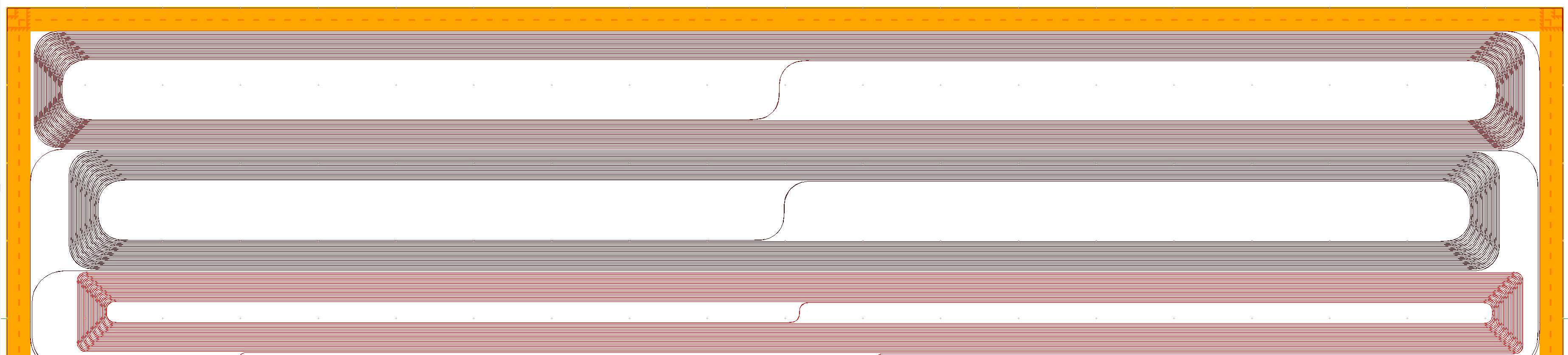
To that end we have designed a new sample for our BDG and SBS experiments, part of which can be seen in Fig. 8. This sample, currently in fabrication, will contain multiple spirals with different applications. The top two spirals are optimized for further BDG measurements These have different tapers, that are optimized for the TM polarization, and a larger bend radius of 300 µm. This will lower the bend losses for the TM mode to 0.015 dB/cm, which will allow the TM mode to travel along the whole waveguide. These waveguides are 1 m long, which enables us the freedom to tune the BDG length over a large range, and also the ability to add a long delay into a BDG reflected signal. These samples will enable us to test and show the many applications for a BDG in silicon nitride waveguides.
Author contributions
D.M., R.B. and J.vd.H developed the concept and proposed the physical system. R.B., J.vd.H. and M.H. developed and performed the numerical simulations. R.B., J.vd.H. and A.M. performed the experiments with input from K.Y., A.v.R. and K.B. R.B. and J.vd.H. wrote the manuscript with input from A.M., A.v.R., K.B. and D.M. D.M. led and supervised the entire project.
Acknowledgements
The authors would like to thank Arjan Meijerink, for his work in designing the new sample.
Funding Information
This project is funded by the Nederlandse Organisatie voor Wetenschappelijk Onderzoek (NWO), project numbers 15702 and 740.018.021.
References
- (1) M. Aspelmeyer, T. J. Kippenberg, and F. Marquardt, “Cavity optomechanics,” Reviews of Modern Physics, vol. 86, no. 4, pp. 1391–1452, 2014.
- (2) A. H. Safavi-Naeini, D. Van Thourhout, R. Baets, and R. Van Laer, “Controlling phonons and photons at the wavelength-scale: silicon photonics meets silicon phononics,” Optica, vol. 6, no. 2, pp. 213–232, 2019.
- (3) B. J. Eggleton, C. G. Poulton, P. T. Rakich, M. J. Steel, and G. Bahl, “Brillouin integrated photonics,” Nature Photonics, vol. 13, no. 10, pp. 664–677, 2019.
- (4) J. Li, H. Lee, and K. J. Vahala, “Microwave synthesizer using an on-chip Brillouin oscillator,” Nature Communications, vol. 4, p. 2097, 2013.
- (5) D. Marpaung, B. Morrison, M. Pagani, R. Pant, D.-Y. Choi, B. Luther-Davies, S. J. Madden, and B. J. Eggleton, “Low-power, chip-based stimulated Brillouin scattering microwave photonic filter with ultrahigh selectivity,” Optica, vol. 2, no. 2, p. 76, 2015.
- (6) S. Barzanjeh, A. Xuereb, S. Gröblacher, M. Paternostro, C. A. Regal, and E. M. Weig, “Optomechanics for quantum technologies,” Nature Physics, vol. 18, no. 1, pp. 15–24, 2022.
- (7) Y. Dong, T. Jiang, L. Teng, H. Zhang, L. Chen, X. Bao, and Z. Lu, “Sub-MHz ultrahigh-resolution optical spectrometry based on Brillouin dynamic gratings,” Optics Letters, vol. 39, no. 10, p. 2967, 2014.
- (8) Y. H. Kim and K. Y. Song, “Characterization of Nonlinear Temperature Dependence of Brillouin Dynamic Grating Spectra in Polarization-Maintaining Fibers,” Journal of Lightwave Technology, vol. 33, no. 23, pp. 4922–4927, 2015.
- (9) J. Li, K. Vahala, and M.-G. Suh, “Microresonator Brillouin gyroscope,” Optica, vol. 4, no. 3, pp. 346–348, 2017.
- (10) B.-B. Li, J. Bílek, U. B. Hoff, L. S. Madsen, S. Forstner, V. Prakash, C. Schäfermeier, T. Gehring, W. P. Bowen, and U. L. Andersen, “Quantum enhanced optomechanical magnetometry,” Optica, vol. 5, no. 7, p. 850, 2018.
- (11) S. Chin and L. Thévenaz, “Tunable photonic delay lines in optical fibers,” Laser & Photonics Reviews, vol. 6, no. 6, pp. 724–738, 2012.
- (12) M. Merklein, B. Stiller, and B. J. Eggleton, “Brillouin-based light storage and delay techniques,” Journal of Optics, vol. 20, no. 8, p. 083003, 2018.
- (13) J. Sancho, N. Primerov, S. Chin, Y. Antman, A. Zadok, S. Sales, and L. Thévenaz, “Tunable and reconfigurable multi-tap microwave photonic filter based on dynamic Brillouin gratings in fibers,” Optics Express, vol. 20, no. 6, p. 6157, 2012.
- (14) M. Santagiustina, S. Chin, N. Primerov, L. Ursini, and L. Thévenaz, “All-optical signal processing using dynamic Brillouin gratings,” Scientific Reports, vol. 3, no. 1, p. 1594, 2013.
- (15) K. Y. Song, W. Zou, Z. He, and K. Hotate, “All-optical dynamic grating generation based on Brillouin scattering in polarization-maintaining fiber,” Optics Letters, vol. 33, no. 9, p. 926, 2008.
- (16) K. Y. Song, “Operation of Brillouin dynamic grating in single-mode optical fibers,” Optics Letters, vol. 36, no. 23, p. 4686, 2011.
- (17) S. Li, M.-J. Li, and R. S. Vodhanel, “All-optical Brillouin dynamic grating generation in few-mode optical fiber,” Optics Letters, vol. 37, no. 22, p. 4660, 2012.
- (18) R. Pant, E. Li, C. G. Poulton, D.-Y. Choi, S. Madden, B. Luther-Davies, and B. J. Eggleton, “Observation of Brillouin dynamic grating in a photonic chip,” Optics Letters, vol. 38, no. 3, p. 305, 2013.
- (19) R. Botter, K. Ye, Y. Klaver, R. Suryadharma, O. Daulay, G. Liu, J. van den Hoogen, L. Kanger, P. van der Slot, E. Klein, M. Hoekman, C. Roeloffzen, Y. Liu, and D. Marpaung, “Guided-acoustic stimulated Brillouin scattering in silicon nitride photonic circuits,” Science advances, vol. 8, no. 40, p. eabq2196, 2022.
- (20) C. G. H. Roeloffzen, M. Hoekman, E. J. Klein, L. S. Wevers, R. B. Timens, D. Marchenko, D. Geskus, R. Dekker, A. Alippi, R. Grootjans, A. van Rees, R. M. Oldenbeuving, J. P. Epping, R. G. Heideman, K. Wörhoff, A. Leinse, D. Geuzebroek, E. Schreuder, P. W. van Dijk, I. Visscher, C. Taddei, Y. Fan, C. Taballione, Y. Liu, D. Marpaung, L. Zhuang, M. Benelajla, and K.-J. Boller, “Low-Loss Si3N4 TriPleX Optical Waveguides: Technology and Applications Overview,” IEEE Journal of Selected Topics in Quantum Electronics, vol. 24, no. 4, pp. 1–21, 2018.
- (21) O. Daulay, G. Liu, K. Ye, R. Botter, Y. Klaver, Q. Tan, H. Yu, M. Hoekman, E. Klein, C. Roeloffzen, Y. Liu, and D. Marpaung, “Ultrahigh dynamic range and low noise figure programmable integrated microwave photonic filter,” Nature Communications, vol. 13, no. 1, p. 7798, 2022.
- (22) G. Liu, K. Ye, O. Daulay, Q. Tan, H. Yu, and D. Marpaung, “Linearized integrated microwave photonic circuit for filtering and phase shifting,” APL Photonics, vol. 8, no. 5, 2023.
- (23) A. Bergman and M. Tur, “Brillouin Dynamic Gratings—A Practical Form of Brillouin Enhanced Four Wave Mixing in Waveguides: The First Decade and Beyond,” Sensors, vol. 18, no. 9, p. 2863, 2018.
- (24) R. W. Boyd, Nonlinear Optics. Elsevier Science Publishing Co Inc, 2008.
- (25) G. P. Agrawal, Nonlinear Fiber Optics, 5th ed. Elsevier Science Publishing Co Inc, 2013.
- (26) Y. Dong, L. Chen, and X. Bao, “Characterization of the Brillouin grating spectra in a polarization-maintaining fiber,” Optics Express, vol. 18, no. 18, p. 18960, 2010.
- (27) R. M. Oldenbeuving, E. J. Klein, H. L. Offerhaus, C. J. Lee, H. Song, and K.-J. Boller, “25 kHz narrow spectral bandwidth of a wavelength tunable diode laser with a short waveguide-based external cavity,” Laser Physics Letters, vol. 10, no. 1, p. 015804, 2013.
- (28) Y. Fan, J. P. Epping, R. M. Oldenbeuving, C. G. H. Roeloffzen, M. Hoekman, R. Dekker, R. G. Heideman, P. J. M. van der Slot, and K.-J. Boller, “Optically Integrated InP–Si3 N4 Hybrid Laser,” IEEE Photonics Journal, vol. 8, no. 6, pp. 1–11, 2016.
- (29) A. van Rees, Y. Fan, D. Geskus, E. J. Klein, R. M. Oldenbeuving, P. J. M. van der Slot, and K.-J. Boller, “Ring resonator enhanced mode-hop-free wavelength tuning of an integrated extended-cavity laser,” Optics Express, vol. 28, no. 4, p. 5669, 2020.