Modular Superconducting Qubit Architecture
with a Multi-chip Tunable Coupler
Abstract
We use a floating tunable coupler to mediate interactions between qubits on separate chips to build a modular architecture. We demonstrate three different designs of multi-chip tunable couplers using vacuum gap capacitors or superconducting indium bump bonds to connect the coupler to a microwave line on a common substrate and then connect to the qubit on the next chip. We show that the zero-coupling condition between qubits on separate chips can be achieved in each design and that the relaxation rates for the coupler and qubits are not noticeably affected by the extra circuit elements. Finally, we demonstrate two-qubit gate operations with fidelity at the same level as qubits with a tunable coupler on a single chip. Using one or more indium bonds does not degrade qubit coherence or impact the performance of two-qubit gates.
I Introduction
To realize the promise of quantum computing, we require systems with sufficiently low error rates to execute algorithms without being overwhelmed by noise and errors. For superconducting quantum processors, one of the challenges is being able to scale up the number of qubits in an architecture without introducing additional channels for correlated gate errors. One possible solution is to use a modular approach where small high-yielding quantum processors are assembled into larger systems using quantum coherent interconnects [1, 2, 3, 4, 5, 6, 7]. Ultimately, scaling quantum processors while maintaining gate errors below a threshold value should allow the error rate to be reduced by the use of error correction of logical qubits made up of many physical qubits [8, 9, 10, 11, 12].
On superconducting quantum processors, modular architectures allow larger devices to be built from smaller units, which increases yield and allows for pre-screening before integration. Such modular architectures enable better-performing devices for the assembled processor when compared with larger monolithic devices [13, 14]. Modular devices also have the advantage of increased isolation between units reducing cross-talk and correlated errors, such as those produced by high-energy background radiation [15, 16, 17]. High-fidelity entanglement of qubits on separate chips was previously demonstrated using static capacitive coupling of frequency tunable qubits to a co-planar transmission line that spanned adjacent chips [18].
Suppressing error rates has been an active area of research to improve the performance of superconducting quantum processors. In particular, tunable couplers have been introduced as useful components to both minimize always-on ZZ interactions and implement fast entangling gates with two-qubit gate fidelities approaching 99.9% [19]. While tunable couplers have been investigated only on single-chip configurations, a direct qubit-qubit capacitance is not required for the floating tunable coupler, making it a potentially compatible component for modular architectures.
In this work, we implement a floating tunable coupler to couple qubits on separate chips to enable high performance in a scalable modular architecture. We first engineer an inter-chip tunable coupler design that is compatible with a modular architecture and robust against modular packaging complexities. Once we have this basic design we then consider three specific variations with increasing packaging complexity and experimentally validate that the inter-chip coupler designs can mediate both high- and low-coupling interactions between qubits on separate chips without degrading qubit coherence. We also demonstrate a 56 ns parametric-resonance CZ gate with fidelity as high as between qubits on separate chips, reaching performance that is comparable to the two-qubit gate realized on qubits fabricated on the same chip.
II Device Design and Fabrication
II.1 Design of a Multi-Chip Tunable Coupler
For two qubits coupled by a floating tunable coupler, the qubit-coupler and qubit-qubit couplings are given by [20]:
| (1) | ||||
| (2) |
where and are the Josephson and charging energies for the qubits and coupler , and is the junction energy of the coupler frequency. The coupling energy between the qubit and coupler, , and qubit to qubit, , are determined by the capacitances between the pads of the floating coupler and the pads of the qubits. The signs of the coupling energies are determined by the capacitance relationships so that is always negative, and and have the opposite (same) signs depending on whether the floating coupler has an asymmetric (symmetric) pad configuration, as previously shown in Ref. [20]. Furthermore, the magnitude of is determined by the capacitances of the nearest-neighbor qubit-coupler pads and does not depend on a direct qubit-qubit capacitance.
The net qubit-qubit coupling is determined by and an effective virtual interaction mediated by the floating tunable coupler:
| (3) | ||||
| (4) |
where and , and the qubit frequencies are (=1,2). The coupler frequency is , where with and being the total junction energy of SQUID junctions of the coupler, and . When is large enough to offset , a condition can be reached for specific values of which turns off the coupling between the qubits. Since the direct capacitance is not assumed in Eq. 2, direct qubit-qubit coupling is not significantly limited by the qubit-qubit separation, and the coupled qubits can be spatially separated onto separate chips as long as there is sufficient capacitance between nearest-neighbor qubit-coupler pads.
II.2 Multi-Chip Tunable Coupler Assembly
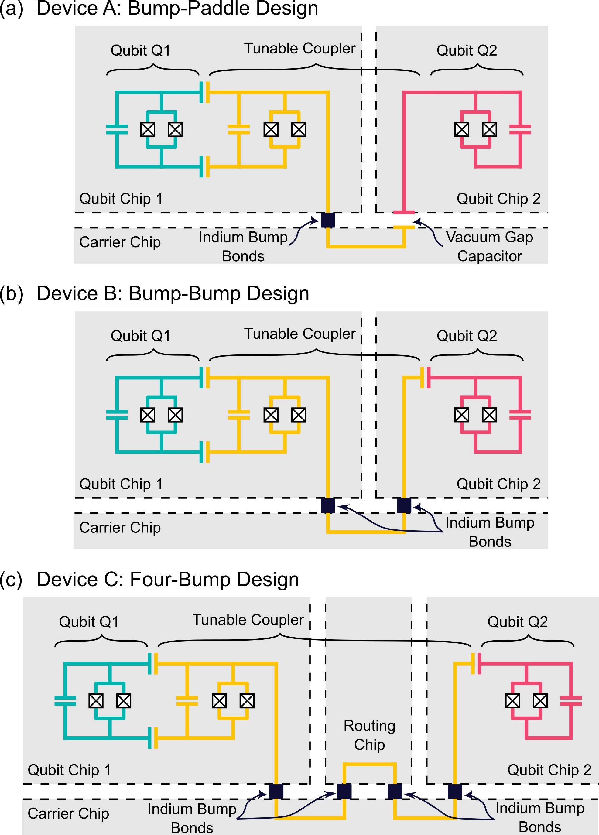
To create a tunable coupler transmon that bridges multiple chips, we consider an architecture consisting of two distinct qubit chips bonded to a common carrier chip. Qubit Chip 1 includes one qubit as well as the SQUID loop defining the tunable coupler and the second qubit is placed on a separate Qubit Chip 2. The SQUID loop of the tunable coupler is fabricated on a qubit chip instead of a separate chip in order to reduce the number of different chips requiring complex lithography. To complete the qubit-coupler-qubit unit, the tunable coupler arm extends through the carrier chip as shown in Fig. 1(a)-(b). An arbitrary number of additional routing chips can be added along the tunable coupler pathway, depending on the multi-chip assembly needs [Fig. 1(c)]. This yields an architecture that is modular and flexible.
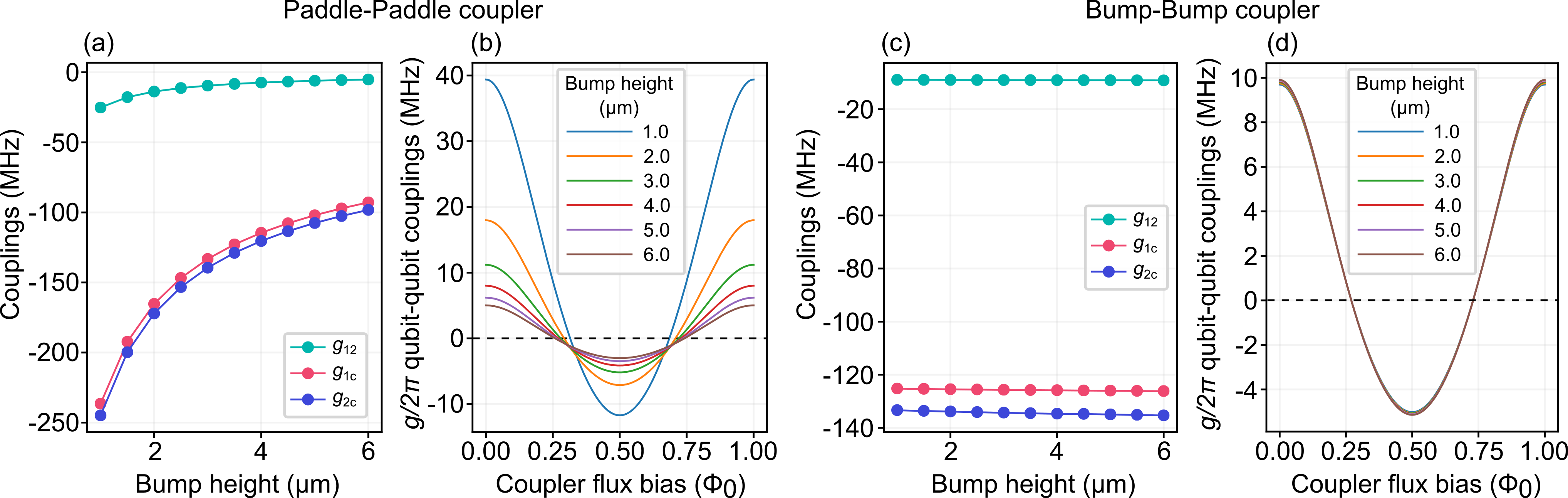
When multi-chip assemblies with static inter-chip coupling were previously studied, the static coupling was mediated through vacuum gap capacitors with plates on the qubit and carrier chips, resulting in a coupling strength that depended on the chip-to-chip separation [18]. In practice, chip-to-chip separation is defined by the heights of the indium bump connectors and therefore subject to fabrication variations. In Fig. 2 we report the simulated impact of indium bump heights on a multi-chip tunable coupler assembly that uses capacitive vacuum gap structures and compare it with a more robust multi-chip tunable coupler architecture using indium bump bonds to provide a direct connection.
The vacuum gap capacitor in a multi-chip coupler assembly contributes to the qubit-coupler coupling energies. As a result, fluctuations in the connector bump height result in variations in , , and [Fig. 2(a)], which impacts the overall dependence on coupler flux bias [Fig. 2(b)]. In particular, the flux bias needed to reach varies with indium bump height, and the maximum magnitude of can vary by 20 MHz for 1 m of bump height variation.
To mitigate the impact of the bump height variation on the capacitive parameters of the multi-chip coupler assembly, we replace the capacitive paddles along the coupler arms and instead directly place indium bump connectors along the path of the coupler arm. This is shown schematically in Fig. 1 for the three designs we consider: Bump-Paddle, Bump-Bump, and Four-Bump. By removing the capacitive variation in the coupler path, the qubit-qubit coupling dependence on coupler flux is not impacted by bump height variations [Fig. 2(c)-(d)], providing a more robust design for the multi-chip coupler.
II.3 Fabrication
The individual qubit chips are fabricated using standard lithographic techniques on high-resistivity silicon substrates. Superconducting circuit components, including the capacitor pads of the transmon qubit structure, ground planes, signal coplanar waveguides, and resonators, are fabricated in niobium metal by deposition, optical lithography, etch, and liftoff steps [21]. The transmon Josephson junctions are fabricated using electron beam lithography with double-angle evaporation of aluminum with in-situ oxidation to form the tunnel barrier.
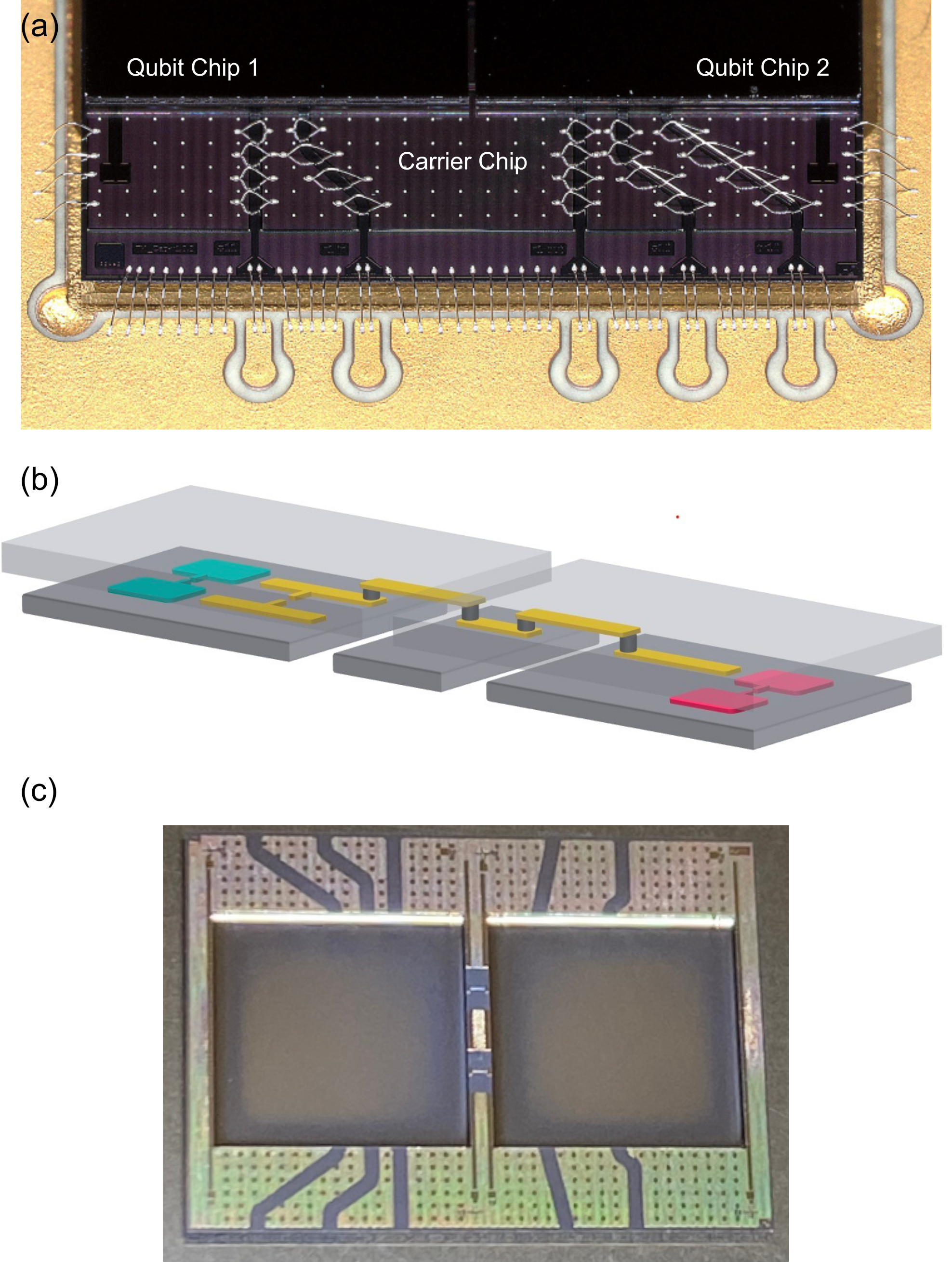
The qubit chips are then bump bonded to a carrier chip using indium bump connectors, resulting in a multi-chip assembly with a superconducting Faraday cage around each qubit and routing for microwave signal lines. Flip-chip bonding of the carrier and qubit modules is accomplished through the deposition and patterning of indium bumps of height 6.5 m and 40 m diameter onto the carrier chip. The qubit chips are flipped and aligned to the carrier before thermo-compression bonding, creating a metallic bond between the carrier and qubit chips [21] which goes superconducting below the transition temperature of indium at K. In the case of the bump-paddle design, the vacuum gap capacitor is formed by two large area superconducting pads separated by a vertical distance of 3 m. In this experiment, the qubit transmon structures are entirely contained on the individual qubit chips, while the coupler is one resonant superconducting element extending over several surfaces and made up of niobium coplanar transmission lines, aluminum Josephson junctions, and indium bump bonds.
A multi-chip test assembly is constructed through the bonding of two or more chips to a larger carrier chip as shown in Fig. 3. In this picture, the smaller individual chips have a single flux tunable transmon qubit and corresponding readout resonators, along with part of the tunable coupler oriented along the horizontal axis towards the chip edges that are adjacent to each other. The control lines for flux bias control of the qubits and the tunable couplers, as well as the readout lines, are integrated into the carrier chip. Two qubit chips bonded to a common carrier chip, as shown in Fig. 3(a), allows the implementation of the Bump-Paddle and Bump-Bump designs. This design could be extended to include an arbitrary number of chips with multi-chip tunable couplers spanning each gap to connect qubits making up a larger processor. A simple version of this is the Four-Bump design shown in Fig. 3(b) where an additional signal routing chip shown in Fig. 3(c) is added in.
III Experimental demonstration
We now validate the multi-chip tunable coupler architecture by measuring three devices. On Device A, the inter-chip connections are made with one indium bump connector along the coupler (Bump-Paddle design, Fig. 1(a)). On Device B, the inter-chip connections are made with two indium bump connectors (Bump-Bump design, Fig. 1(b)). We also test a device with increased qubit-qubit separation on Device C, whose multi-chip coupler goes through an additional routing chip as well as two carrier chips and has a total of four indium bumps (Four-Bump design) as shown in Fig. 1(c). To experimentally verify that different types of floating coupler configurations can be used on multi-chip coupler assemblies, we measure devices with both an asymmetric (Devices A and B) and symmetric (Device C) coupler configuration.
III.1 Tunable inter-chip coupling
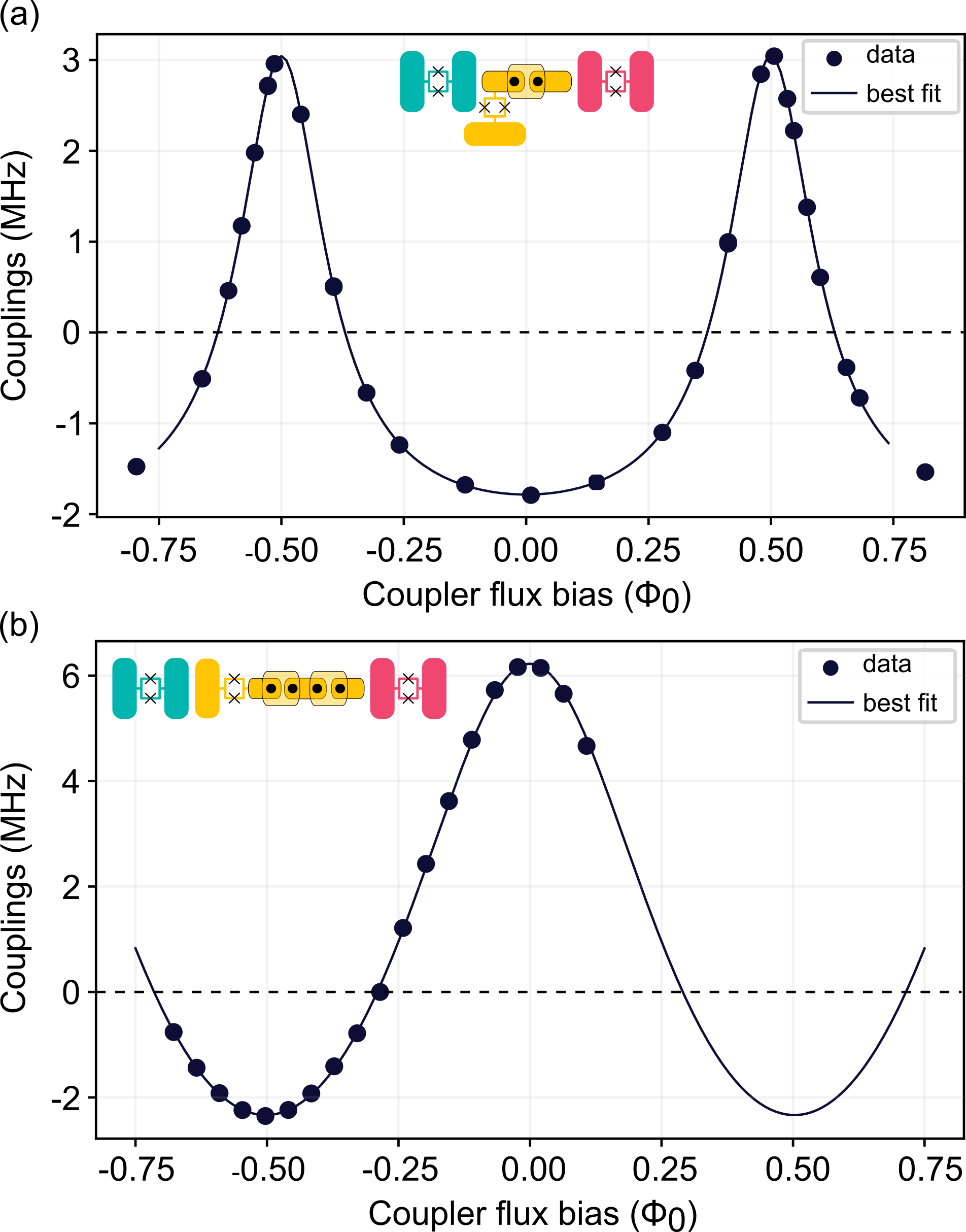
To demonstrate that the multi-chip couplers can mediate both low- and high-coupling interactions between qubits, we measure the net coupling as a function of coupler flux. The magnitude of is measured from the energy exchange between the and states, which is enacted using a parametric-resonance gate [22]. The sign of is then inferred based on the expected curves for a floating asymmetric or symmetric tunable coupler, and approximate values of the coupling parameters can be extracted by fitting the data to Eq. (4) [20]. We show these approximate coupling values in Table 1, but it is important to note that , , and have a dependence on .
We first present coupling data for a Bump-Bump design (Device B). The tunable coupler has an asymmetric floating coupler configuration so that when the coupler is at its maximum frequency, will reach its minimum value. The coupling can be tuned from -2 to 3 MHz and a zero coupling condition is attained around , which signifies that there was sufficient direct qubit-qubit coupling to offset [Fig. 4(a)]. We extract approximate coupling values MHz and MHz. These coupling values are similar to those of previous tunable coupler devices fabricated on a single chip [20].
We now look at when the modular device is extended to four chips with the Four-Bump design on Device C. Device C uses a symmetric tunable coupler, which means that a maximum is reached when the coupler is at its maximum frequency. For Device C, the multi-chip coupler tunes the value of from -2 MHz to 6 MHz [Fig. 4(b)]. Despite the more complex multi-chip assembly, and , on the Four-Bump design are similar to the values reached on the Bump-Bump design [Table 1]. We also measured similar results for an asymmetric floating coupler with a Four-Bump design.
| Bump-Bump | Four-Bump | |
|---|---|---|
| (MHz) | 5.2 (0.4) | 5.2 (0.9) |
| (MHz) | 93 (9) | 94 (6) |
III.2 Impact of multi-chip connections on coherence
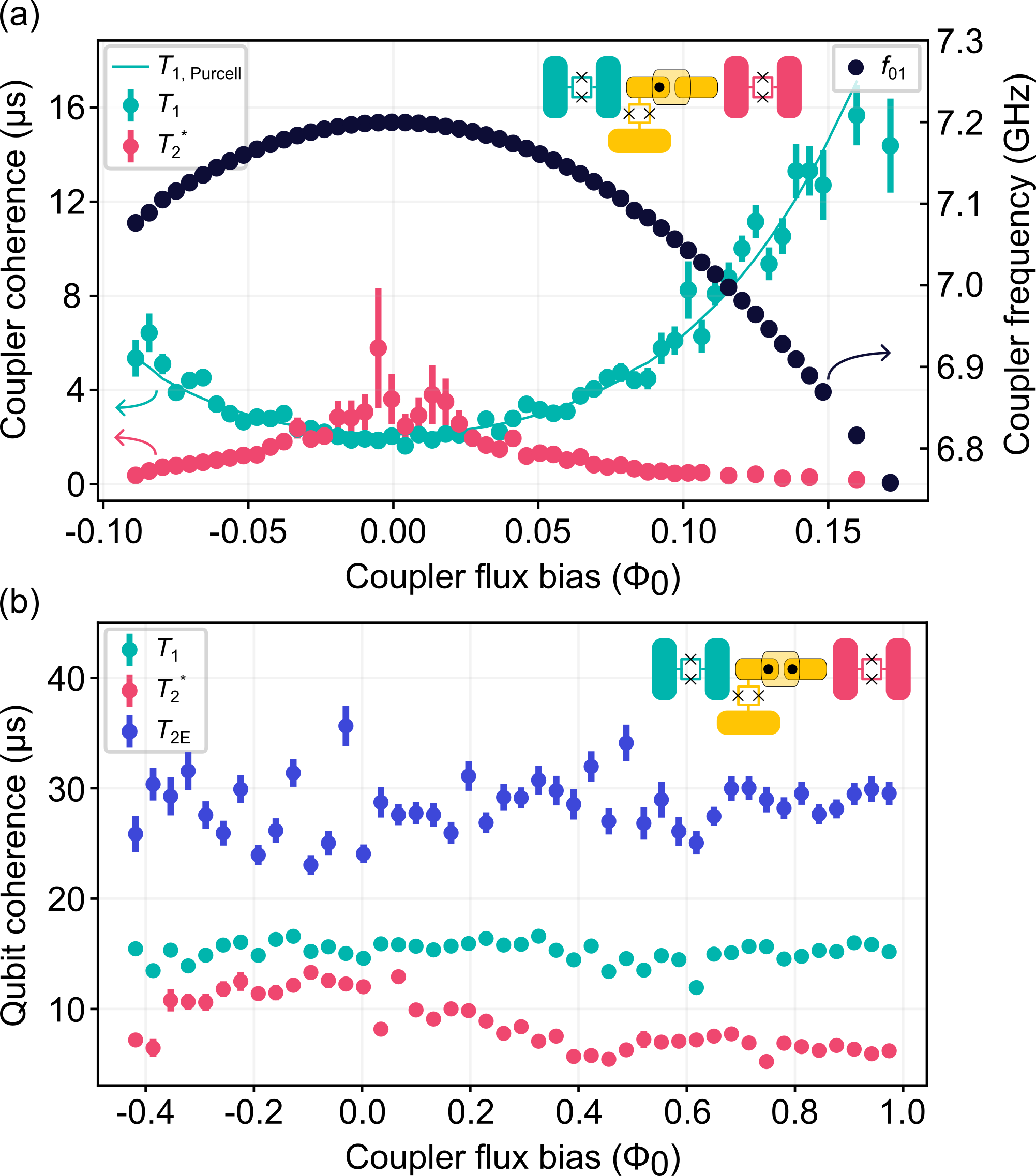
Indium bump connectors were placed along the coupler arms to minimize coupling variations coming from bump height variations. We now verify that the indium bump connectors do not significantly degrade the performance of the multi-chip coupler by measuring the coherence times of the coupler on Device A. The coupler frequency and coherence times near the coupler’s maximum frequency are shown in Fig. 5(a).
The coupler is in an asymmetric configuration, so the coupler frequencies are above the qubit frequencies to make a zero coupling condition attainable. At , the coupler frequency approaches the qubit’s resonator frequency GHz, and of the coupler decreases. Due to the small detuning between the coupler frequency and qubit resonator frequencies, the values of the coupler are mainly Purcell-limited. We also extract the resonator-coupler coupling strength by fitting the equation for a Purcell-limited to the coupler values [23, 24, 25]
where and are the decay rates and frequencies for the qubit resonator. The fit yields a coupling value MHz. However, because Device A uses a Bump-Paddle design instead of a Bump-Bump design, coupling values on the device generally overshot design values due to the extra variability introduced by the additional gap paddle. In general, of the coupler shows a dependence on coupler-resonator detuning that is consistent with the Purcell effect, which suggests that the quality factor of the multi-chip tunable coupler is not detrimentally impacted by the nearby indium bump connectors. Furthermore, when the coupler was at , of the coupled qubits were around 20 s, which suggests that the qubits are not limited by the s of the tunable coupler at the coupler’s maximum frequency.
We also measure the qubit coherence as a function of the tunable coupler flux when an additional indium bump is added to the coupler arm on Device B, which has an asymmetric coupler with frequencies above the qubit. The coupler is furthest from the qubit frequency at zero coupler flux bias and approaches the qubit frequencies when the coupler flux bias is at . and of the qubit do not change in this range as shown in Fig. 5(b), so the qubit coherence is not limited by the coupler coherence times. There is some degradation in in the measurement run, but the degradation is not related to the coupler frequency or the amount of flux applied to the coupler. This degradation is likely coming from the qubit moving off of during the measurement due to classical flux cross-talk that was not corrected. Coherence times , , and on the other coupled qubit do not show any change with coupler bias.
III.3 Two-qubit gate performance
As a final validation of the multi-chip coupler architecture, we use the tunable coupler to entangle two qubits on separate chips. We look specifically at implementing a CZ gate between qubits on Device C, whose coupler bridges four chips and traverses four indium bumps.
Similar to Ref. [22], the CZ gate is implemented as a parametric-resonance gate, where a modulated flux pulse brings the average frequency of one qubit on resonance with the transition of the other qubit. A dc flux pulse is simultaneously applied to the multi-chip coupler to move from zero coupling to a larger magnitude. On Device C, we enact a 56 ns CZ gate by moving the multi-chip coupler frequency to the maximum coupling.
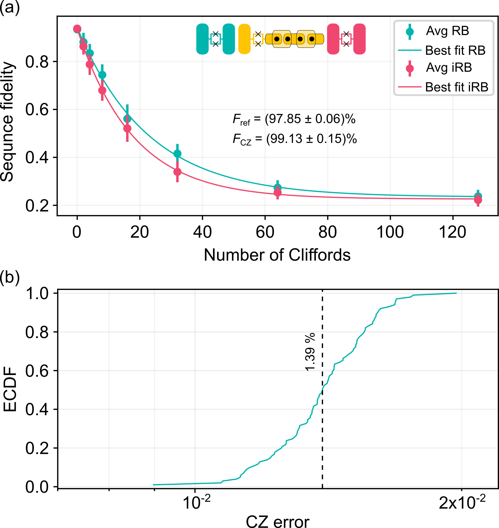
We benchmark the CZ gate using two-qubit interleaved randomized benchmarking (iRB) [26], shown in Fig. 6(a), and measure the CZ gate fidelity to be . The coherence-limited fidelity can be estimated using
where the tilde refers to the coherence time of the modulated qubit. The CZ gate time included the gate interaction time = 56 ns and the padding on each side of the flux pulses = 4 ns. The measured coherence times are s, s, s, and s, so the coherence-limited fidelity is estimated to be , which is close to the measured fidelity. We also monitor the stability of the CZ gate by measuring the iRB fidelity over a span of 7 hours without re-calibrating the two-qubit gate and qubit readout, as shown in Fig. 6(b). The two-qubit gate is stable over this time with an average fidelity and standard deviation of .
IV Conclusion
We have demonstrated an architecture where a tunable coupler spans multiple chips using either vacuum gap capacitors or indium bump bonds in the coupler arms to route the signal via intermediate chips. This architecture allows the combination of the low-error capabilities of a tunable coupler with modular assembly techniques. Furthermore, the coupler design makes use of the fact that the floating coupler does not depend on a direct qubit-qubit capacitance to reach a zero-coupling condition, therefore allowing qubits to be placed on separate chips. We reduce the impact of fabrication variation on the coupling strength and zero bias condition by introducing indium bump connectors into the arms of the tunable couplers to replace vacuum gap capacitors, which are otherwise sensitive to the vertical distance between bonded chips.
We experimentally validated the multi-chip tunable coupler architecture on three different devices, covering configurations where the coupler bridges 3 chips or 4 chips and the coupler is either in an asymmetric or symmetric configuration. Net coupling values comparable to what has been measured in single-chip devices were measured [22]. Furthermore, the coherence times of the multi-chip coupler and the coupled qubits suggest that the location of the indium bump connectors does not significantly degrade the performance of the transmons on the device. We also check that the multi-chip coupler can mediate high-fidelity qubit-qubit interactions: we measure iRB fidelities up to % when performing a 56 ns CZ gate using a coupler that bridges 4 separate chips. Hence, despite the increased assembly complexity, the multi-chip coupler device performs comparably to similar single-chip devices.
Acknowledgments
The authors would like to thank Riccardo Manenti and Beatriz Yankelevich for initial characterizations of multi-chip coupler devices, and Theo Paran for help with resist development in fabricating the routing chip.
Contributions
M.F. and A.Q.C contributed equally to this work. M.F. coordinated the experiment and sample preparation. A.Q.C., E.A.S., and S.P. performed the measurements and data analysis. B.S. designed all the devices and ran the simulations to demonstrate the performance with theory input from E.A.S. F.O., K.U., and V.K. created the cleanroom processes used to fabricate the samples and oversaw the sample bonding. S.P., J.M., and A.B. lead the effort. A.Q.C, M.F., E.A.S., and S.P. drafted the manuscript. All authors contributed to the editing of the manuscript.
References
- Awschalom et al. [2021] D. Awschalom, K. K. Berggren, H. Bernien, S. Bhave, L. D. Carr, P. Davids, S. E. Economou, D. Englund, A. Faraon, M. Fejer, S. Guha, M. V. Gustafsson, E. Hu, L. Jiang, J. Kim, B. Korzh, P. Kumar, P. G. Kwiat, M. Lončar, M. D. Lukin, D. A. Miller, C. Monroe, S. W. Nam, P. Narang, J. S. Orcutt, M. G. Raymer, A. H. Safavi-Naeini, M. Spiropulu, K. Srinivasan, S. Sun, J. Vučković, E. Waks, R. Walsworth, A. M. Weiner, and Z. Zhang, Development of Quantum Interconnects (QuICs) for Next-Generation Information Technologies, PRX Quantum 2, 017002 (2021).
- Jiang et al. [2007] L. Jiang, J. M. Taylor, A. S. Sørensen, and M. D. Lukin, Distributed quantum computation based on small quantum registers, Physical Review A 76, 062323 (2007).
- Kimble [2008] H. J. Kimble, The quantum internet, Nature 453, 1023 (2008).
- Chou et al. [2018] K. S. Chou, J. Z. Blumoff, C. S. Wang, P. C. Reinhold, C. J. Axline, Y. Y. Gao, L. Frunzio, M. H. Devoret, L. Jiang, and R. J. Schoelkopf, Deterministic teleportation of a quantum gate between two logical qubits, Nature 561, 368 (2018).
- Wan et al. [2019] Y. Wan, D. Kienzler, S. D. Erickson, K. H. Mayer, T. R. Tan, J. J. Wu, H. M. Vasconcelos, S. Glancy, E. Knill, D. J. Wineland, A. C. Wilson, and D. Leibfried, Quantum gate teleportation between separated qubits in a trapped-ion processor, Science 364, 875 (2019).
- Hensen et al. [2015] B. Hensen, H. Bernien, A. E. Dréau, A. Reiserer, N. Kalb, M. S. Blok, J. Ruitenberg, R. F. L. Vermeulen, R. N. Schouten, C. Abellán, W. Amaya, V. Pruneri, M. W. Mitchell, M. Markham, D. J. Twitchen, D. Elkouss, S. Wehner, T. H. Taminiau, and R. Hanson, Loophole-free Bell inequality violation using electron spins separated by 1.3 kilometres, Nature 526, 682 (2015).
- Monroe et al. [2014] C. Monroe, R. Raussendorf, A. Ruthven, K. R. Brown, P. Maunz, L.-M. Duan, and J. Kim, Large-scale modular quantum-computer architecture with atomic memory and photonic interconnects, Physical Review A 89, 022317 (2014).
- Kitaev [2003] A. Kitaev, Fault-tolerant quantum computation by anyons, Annals of Physics 303, 2 (2003).
- Fowler et al. [2012] A. G. Fowler, M. Mariantoni, J. M. Martinis, and A. N. Cleland, Surface codes: Towards practical large-scale quantum computation, Phys. Rev. A 86, 032324 (2012).
- Raussendorf and Harrington [2007] R. Raussendorf and J. Harrington, Fault-tolerant quantum computation with high threshold in two dimensions, Phys. Rev. Lett. 98, 190504 (2007).
- Krinner et al. [2022] S. Krinner, N. Lacroix, A. Remm, A. Di Paolo, E. Genois, C. Leroux, C. Hellings, S. Lazar, F. Swiadek, J. Herrmann, G. J. Norris, C. K. Andersen, M. Müller, A. Blais, C. Eichler, and A. Wallraff, Realizing repeated quantum error correction in a distance-three surface code, Nature 605, 669 (2022).
- Acharya et al. [2023] R. Acharya, I. Aleiner, R. Allen, T. I. Andersen, M. Ansmann, F. Arute, K. Arya, A. Asfaw, J. Atalaya, R. Babbush, D. Bacon, J. C. Bardin, J. Basso, A. Bengtsson, S. Boixo, G. Bortoli, A. Bourassa, J. Bovaird, L. Brill, M. Broughton, B. B. Buckley, D. A. Buell, T. Burger, B. Burkett, N. Bushnell, Y. Chen, Z. Chen, B. Chiaro, J. Cogan, R. Collins, P. Conner, W. Courtney, A. L. Crook, B. Curtin, D. M. Debroy, A. Del Toro Barba, S. Demura, A. Dunsworth, D. Eppens, C. Erickson, L. Faoro, E. Farhi, R. Fatemi, L. Flores Burgos, E. Forati, A. G. Fowler, B. Foxen, W. Giang, C. Gidney, D. Gilboa, M. Giustina, A. Grajales Dau, J. A. Gross, S. Habegger, M. C. Hamilton, M. P. Harrigan, S. D. Harrington, O. Higgott, J. Hilton, M. Hoffmann, S. Hong, T. Huang, A. Huff, W. J. Huggins, L. B. Ioffe, S. V. Isakov, J. Iveland, E. Jeffrey, Z. Jiang, C. Jones, P. Juhas, D. Kafri, K. Kechedzhi, J. Kelly, T. Khattar, M. Khezri, M. Kieferová, S. Kim, A. Kitaev, P. V. Klimov, A. R. Klots, A. N. Korotkov, F. Kostritsa, J. M. Kreikebaum, D. Landhuis, P. Laptev, K.-M. Lau, L. Laws, J. Lee, K. Lee, B. J. Lester, A. Lill, W. Liu, A. Locharla, E. Lucero, F. D. Malone, J. Marshall, O. Martin, J. R. McClean, T. McCourt, M. McEwen, A. Megrant, B. Meurer Costa, X. Mi, K. C. Miao, M. Mohseni, S. Montazeri, A. Morvan, E. Mount, W. Mruczkiewicz, O. Naaman, M. Neeley, C. Neill, A. Nersisyan, H. Neven, M. Newman, J. H. Ng, A. Nguyen, M. Nguyen, M. Y. Niu, T. E. O’Brien, A. Opremcak, J. Platt, A. Petukhov, R. Potter, L. P. Pryadko, C. Quintana, P. Roushan, N. C. Rubin, N. Saei, D. Sank, K. Sankaragomathi, K. J. Satzinger, H. F. Schurkus, C. Schuster, M. J. Shearn, A. Shorter, V. Shvarts, J. Skruzny, V. Smelyanskiy, W. C. Smith, G. Sterling, D. Strain, M. Szalay, A. Torres, G. Vidal, B. Villalonga, C. Vollgraff Heidweiller, T. White, C. Xing, Z. J. Yao, P. Yeh, J. Yoo, G. Young, A. Zalcman, Y. Zhang, N. Zhu, and G. Q. AI, Suppressing quantum errors by scaling a surface code logical qubit, Nature 614, 676 (2023).
- Brink et al. [2018] M. Brink, J. M. Chow, J. Hertzberg, E. Magesan, and S. Rosenblatt, Device challenges for near term superconducting quantum processors: Frequency collisions, in 2018 IEEE International Electron Devices Meeting (IEDM) (2018) pp. 6.1.1–6.1.3.
- Dickel et al. [2018] C. Dickel, J. J. Wesdorp, N. K. Langford, S. Peiter, R. Sagastizabal, A. Bruno, B. Criger, F. Motzoi, and L. DiCarlo, Chip-to-chip entanglement of transmon qubits using engineered measurement fields, Physical Review B 97, 064508 (2018).
- Wilen et al. [2021] C. D. Wilen, S. Abdullah, N. A. Kurinsky, C. Stanford, L. Cardani, G. D’Imperio, C. Tomei, L. Faoro, L. B. Ioffe, C. H. Liu, A. Opremcak, B. G. Christensen, J. L. DuBois, and R. McDermott, Correlated charge noise and relaxation errors in superconducting qubits, Nature 594, 369 (2021).
- Vepsäläinen et al. [2020] A. P. Vepsäläinen, A. H. Karamlou, J. L. Orrell, A. S. Dogra, B. Loer, F. Vasconcelos, D. K. Kim, A. J. Melville, B. M. Niedzielski, J. L. Yoder, S. Gustavsson, J. A. Formaggio, B. A. VanDevender, and W. D. Oliver, Impact of ionizing radiation on superconducting qubit coherence, Nature 584, 551 (2020).
- Cardani et al. [2021] L. Cardani, F. Valenti, N. Casali, G. Catelani, T. Charpentier, M. Clemenza, I. Colantoni, A. Cruciani, G. D’Imperio, L. Gironi, L. Grünhaupt, D. Gusenkova, F. Henriques, M. Lagoin, M. Martinez, G. Pettinari, C. Rusconi, O. Sander, C. Tomei, A. V. Ustinov, M. Weber, W. Wernsdorfer, M. Vignati, S. Pirro, and I. M. Pop, Reducing the impact of radioactivity on quantum circuits in a deep-underground facility, Nature Communications 12, 2733 (2021).
- Gold et al. [2021] A. Gold, J. P. Paquette, A. Stockklauser, M. J. Reagor, M. S. Alam, A. Bestwick, N. Didier, A. Nersisyan, F. Oruc, A. Razavi, B. Scharmann, E. A. Sete, B. Sur, D. Venturelli, C. J. Winkleblack, F. Wudarski, M. Harburn, and C. Rigetti, Entanglement across separate silicon dies in a modular superconducting qubit device, npj Quantum Information 7, 1 (2021).
- Yan et al. [2018] F. Yan, P. Krantz, Y. Sung, M. Kjaergaard, D. L. Campbell, T. P. Orlando, S. Gustavsson, and W. D. Oliver, Tunable Coupling Scheme for Implementing High-Fidelity Two-Qubit Gates, Phys. Rev. Applied 10, 054062 (2018).
- Sete et al. [2021a] E. A. Sete, A. Q. Chen, R. Manenti, S. Kulshreshtha, and S. Poletto, Floating Tunable Coupler for Scalable Quantum Computing Architectures, Physical Review Applied 15, 064063 (2021a).
- Nersisyan et al. [2019] A. Nersisyan, S. Poletto, N. Alidoust, R. Manenti, R. Renzas, C.-V. Bui, K. Vu, T. Whyland, Y. Mohan, E. A. Sete, S. Stanwyck, A. Bestwick, and M. Reagor, Manufacturing low dissipation superconducting quantum processors, in 2019 IEEE International Electron Devices Meeting (IEDM) (2019) pp. 31.1.1–31.1.4.
- Sete et al. [2021b] E. A. Sete, N. Didier, A. Q. Chen, S. Kulshreshtha, R. Manenti, and S. Poletto, Parametric-resonance entangling gates with a tunable coupler, Phys. Rev. Appl. 16, 024050 (2021b).
- Kleppner [1981] D. Kleppner, Inhibited spontaneous emission, Phys. Rev. Lett. 47, 233 (1981).
- Goy et al. [1983] P. Goy, J. M. Raimond, M. Gross, and S. Haroche, Observation of cavity-enhanced single-atom spontaneous emission, Phys. Rev. Lett. 50, 1903 (1983).
- Sete et al. [2014] E. A. Sete, J. M. Gambetta, and A. N. Korotkov, Purcell effect with microwave drive: Suppression of qubit relaxation rate, Phys. Rev. B 89, 104516 (2014).
- Magesan et al. [2012] E. Magesan, J. M. Gambetta, and J. Emerson, Characterizing quantum gates via randomized benchmarking, Phys. Rev. A 85, 042311 (2012).