Strong tunable coupling between two distant superconducting spin qubits
Abstract
Superconducting (or Andreev) spin qubits have recently emerged as an alternative qubit platform with realizations in semiconductor-superconductor hybrid nanowires [1, 2]. In these qubits, the spin degree of freedom is intrinsically coupled to the supercurrent across a Josephson junction via the spin-orbit interaction, which facilitates fast, high-fidelity spin readout using circuit quantum electrodynamics techniques [3]. Moreover, this spin-supercurrent coupling has been predicted to facilitate inductive multi-qubit coupling [4, 5]. In this work, we demonstrate a strong supercurrent-mediated coupling between two distant Andreev spin qubits. This qubit-qubit interaction is of the longitudinal type and we show that it is both gate- and flux-tunable up to a coupling strength of . Finally, we find that the coupling can be switched off in-situ using a magnetic flux. Our results demonstrate that integrating microscopic spin states into a superconducting qubit architecture can combine the advantages of both semiconductors and superconducting circuits and pave the way to fast two-qubit gates between remote spins.
Semiconducting spin qubits [6, 7] have proven to be a promising platform for quantum information processing. In such qubits, quantum information is encoded in the spin degree of freedom of electrons or holes localized in quantum dots, which leads to long lifetimes and a naturally large energy separation between computational and non-computational states. Moreover, their small size makes them attractive candidates for large-scale quantum devices [8, 9]. However, it remains challenging to engineer a direct spin-spin coupling between remote spin-qubits as their interaction strength decays rapidly with distance. Ongoing efforts to overcome this challenge focus on engineering a coupling between distant spin-qubits mediated by microwave photons in superconducting resonators [10, 11, 12, 13, 14, 15]. For such photon-mediated spin-spin coupling, the interaction strength is currently limited to the order of , which makes the implementation of fast, long-range two-qubit gates an outstanding challenge [9, 14]. Moreover, the transverse character of the coupling puts a constraint on the available qubit frequencies.
An alternative approach to engineer remote spin-spin coupling is to embed the spin-qubit into a Josephson junction creating a so-called Andreev spin qubit (ASQ) [1, 2], where the qubit states carry a spin-dependent supercurrent [17, 3, 18, 1, 19, 20, 2]. Recent experiments have demonstrated that a single ASQ can be operated coherently with strong coupling of the spin states to superconducting circuits [1, 2]. Similarly, it has been predicted that large spin-dependent supercurrents can lead to strong, longitudinal, long-range and tunable spin-spin coupling [4, 5], thus, overcoming the challenges imposed by the coupling being only a second-order interaction in previous photon-mediated implementations of spin-spin coupling as well as circumventing any strong constraints on the qubit frequencies.
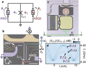
Here, we investigate the supercurrent-mediated coupling between two ASQs by analyzing the influence of a shared Josephson inductance on the coupling strength using the setup in Fig. 1. Specifically, we design a device formed by two Andreev spin qubits, ASQ1 and ASQ2, connected in parallel to a third Josephson junction with gate-tunable Josephson inductance, thus defining two superconducting loops (Fig. 1a). Microscopically, the longitudinal coupling between the qubits directly results from the main characteristic of Andreev spin qubits: their spin to supercurrent coupling. The phase-dependent frequency of one qubit results in a spin-state-dependent circulating supercurrent through the loop arm containing the other qubit. We show that the qubit-qubit coupling in this configuration can be in-situ controlled by the flux through the superconducting loops as well as by changing the Josephson inductance of the shared junction using an electrostatic gate. In particular, we reach the strong longitudinal coupling regime where the coupling strength is larger than the qubit linewidths. Moreover, we show that the coupling can be switched fully off for particular values of the flux, which makes this platform appealing as an alternative for implementing fast flux-controlled two-qubit gates between spin qubits.
I Device
In our device, each ASQ is hosted in a quantum dot Josephson junction which is implemented in a separate Al/InAs nanowire and controlled by three electrostatic gates placed beneath the nanowires (Fig. 1b). Throughout this work, the gate voltages are fixed as specified in the Supplementary Information [16]. Moreover, we define an additional regular Josephson junction with gate-tunable Josephson inductance in one of the nanowires. The nanowires are galvanically connected to a NbTiN circuit which defines the superconducting loops forming a double-loop superconducting quantum interference device (SQUID). We denote by and the external magnetic fluxes through each of the loops. The qubit frequency for ASQ, , where , is set by the energy difference between the spin-states, and , which is controlled by the magnetic field due to the Zeeman effect. We denote the in-plane magnetic field directions as , approximately along the nanowires, and , approximately perpendicular to the nanowires. See also Supplementary Information [16] for additional details on the field alignment. The component of the magnetic field is moreover used to tune and . Note that, while is applied in the chip plane, it still threads flux through the loops due to the elevation of the nanowires with respect to the NbTiN circuitry. This reduces flux jumps compared to using out-of-plane field for flux tuning, as discussed in Ref. [19]. and set the phase drops over the junctions, and in the limit of small , where denotes the magnetic flux quantum. The current through the flux line, , tunes and leaves nearly unaffected, as the loop corresponding to is placed near the symmetry axis of the flux line (see Supplementary information [16]). The drive pulses, with frequencies and , are sent through the central gate of ASQ2 and are used to drive both qubits. We find that it is possible to drive ASQ1 using the gate line of ASQ2 possibly due to cross-coupling between the gate lines corresponding to both qubits or to cross-coupling between the gate line and the transmon island. The coupling junction is controlled by a single electrostatic gate whose voltage, , is varied to tune [21].
To enable readout of the ASQ states, the double-loop SQUID in which the ASQs are hosted is placed between a superconducting island (red) and ground (purple), forming a transmon circuit [22, 23, 24] (Fig. 1b, c). These circuit elements are implemented in -thick NbTiN for magnetic field compatibility [25, 26, 27, 28, 29, 30, 19]. The transmon frequency depends on the energy-phase relation of the double-loop SQUID, which in turn depends on the states of both ASQs [20]. The transmon is subsequently dispersively coupled to a lumped element readout resonator, which is coupled to a feedline implemented with a coplanar waveguide and monitored in transmission using a probe tone at frequency . The readout mechanism is illustrated in Fig. 1d, which shows the four possible frequencies of the readout resonator, caused by the different dispersive shifts of the four spin states of the combined ASQ1-ASQ2 system [31]: . Note that spin is not a well defined quantum number for these states, see 111In an ASQ, the spin is hybridized with spatial degrees of freedom, and thus the eigenstates are rather pseudo-spin states. Similar to previous works [1, 2], we will refer to the eigenstates as spins for simplicity.. The measurement is taken at zero magnetic field where all spin states are thermally occupied on average, since the energy splitting between them is between 0.5 and (see Supplementary Information [16]), which is smaller than typical effective temperatures on the order of observed in these devices [2]. Therefore, the lines corresponding to all four states are visible. This result already illustrates the presence of two separate ASQs in the system. We will now move on to the characterization of these qubits before we turn our attention to the two-qubit coupling.
II Individual Andreev spin qubit characterization
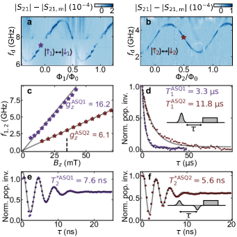
We first characterize each ASQ separately, while the junction containing the other qubit is pinched-off electrostatically using the voltages on its gates (Fig. 2), following the methods of Ref. [2]. To set the qubit frequencies, we apply a magnetic field in the - plane, 0.1 radians away from the direction (see Supplementary Information [16]). This field sets [6, 9] GHz and [2, 4.5] GHz for ASQ1 and ASQ2, respectively. We note that the qubit frequencies are significantly different due to mesoscopic fluctuations in the gate-dependence of the spin-orbit direction and -factor of each ASQ, see also Fig. 2 and Supplementary Information. Qubit spectroscopy is then performed by monitoring the transmission through the feedline near the readout-resonator frequency, while applying a drive tone with frequency to the central gate line of ASQ2, see Fig. 2a, b. On resonance with the qubit transition, we observe a strong change in transmission because spin-orbit coupling and a magnetic field enable electrical driving of the spin [33, 19, 20]. The qubit frequencies, and , can be tuned by flux, as shown in Fig. 2a and b. Note that the phase dispersion is expected to be sinusoidal, see Ref. [5, 34], as is the case for ASQ2. However, for ASQ1 we rather observe a skewed sine. From the ratio of the inductance of ASQ1 and we rule out a non-linear flux-phase relation, so the skewness is currently of unknown origin and could be related to higher orbitals in the quantum dot. While flux tuning provides fine-tuning of the qubit frequency within a frequency band of a few GHz set by the spin-orbit coupling strength, we can also tune the qubit frequencies over a larger range by varying the magnetic field, due to the Zeeman effect. From the magnetic field dependence of the frequencies we extract the -factor of each ASQ, see Fig. 2c. We find that the different -factors are consistent with earlier work [35, 20, 19], see also Supplementary Information [16].
Next, we characterize the coherence properties of each ASQ at the frequencies indicated with markers in Fig. 2a and b. At these setpoints, we extract energy decay times of and for ASQ1 and ASQ2, respectively, where the reported uncertainties are the confidence intervals from the fit. These decay times are to a large extent limited by Purcell decay to the transmon qubit (see Supplementary Information [16]). Furthermore, from a Ramsey experiment, we extract dephasing times of and for ASQ1 and ASQ2, respectively, which are comparable to times found in earlier works [1, 2]. For these measurements, we use Gaussian pulses with a full width at half-maximum (FWHM) of , which is comparable to . Therefore, the pulses cannot be considered instantaneous, which is the conventional assumption in a Ramsey experiment. Rather, a non-zero overlap of the pulses of order can result in an overestimation of the extracted , as further discussed in the Supplementary Information [16]. Therefore, these numbers should be interpreted as an upper bound to the pure dephasing times. Furthermore, we extract echo times of 17.3 and , see Supplementary Information [16], three times larger than , which points at low-frequency noise being a strong contributor to dephasing, consistent with previous observations in InAs-based spin qubits [36, 1, 2].
III Longitudinal coupling
Having two Andreev spin qubits, we describe the joint system by the following Hamiltonian with the two qubits coupled longitudinally with coupling strength [5]:
| (1) |
where and denote the phase-dependent spin-flip frequency and the Pauli matrix of ASQ, respectively, is the Planck constant and . In this description, the longitudinal term originates from the fact that the spin-dependent supercurrent of ASQ1 induces a spin-dependent phase difference over ASQ2, thus changing its transition frequency by , and vice versa. Importantly, the longitudinal coupling does not arise from direct wavefunction overlap [37] or magnetic interactions as the spins are separated by a distance of approximately . From this physical understanding of the interaction, we can express the coupling strength as a function of the circuit parameters by [5]
| (2) |
Here, we define as the total spin-independent inductance of the two ASQs in parallel and the magnitude of the spin-dependent current is captured by which denotes the difference in supercurrent across ASQ for its two possible spin states. In this expression, one of the main features of the device becomes apparent: the coupling is tunable with flux and can be switched to zero when either or are set to zero.
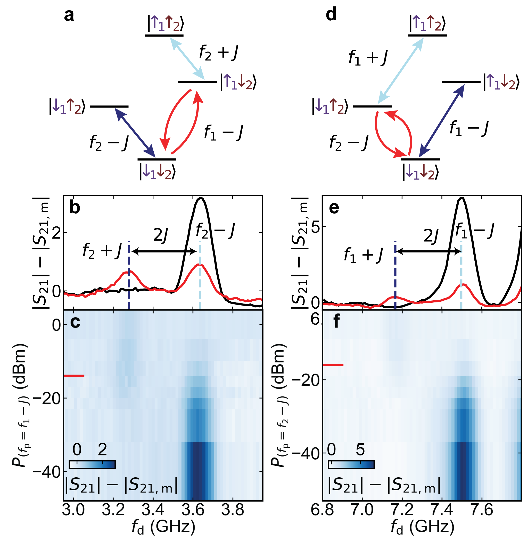
We now proceed to investigate the spin-spin coupling at the same gate voltages and magnetic field used for Fig. 2. To this end, we open both loops simultaneously and set and at points where the slopes of the qubit frequencies are large, close to and . When the two qubits are longitudinally coupled, the transition frequency of each of them depends on the state of the other, as schematically depicted in Fig. 3a and d. In each panel, the blue arrows indicate the two possible frequencies of one qubit, separated by twice the coupling strength, , for the two possible states of the other qubit. To determine the magnitude of the coupling strength, we perform the following measurements: First, we determine by performing qubit spectroscopy of ASQ2 starting from the ground state, , where ASQ1 is in the spin-down state (black trace in Fig. 3b). Then, we repeat the spectroscopy while applying another continuous pump tone at a frequency resonant with the spin-flip transition of ASQ1, driving . The presence of this additional tone results in ASQ1 being in a mixture of and . When performing spectroscopy of ASQ2 under these conditions (red trace in Fig. 3b), we observe the emergence of a second peak corresponding to the shifted frequency of ASQ2 due to ASQ1 having population in its excited state, . This frequency splitting arises from the longitudinal coupling term and, thus, we determine the value of MHz from a double Gaussian fit as half of the difference between the two frequencies (see the Supplementary Information for details on the fit procedure [16]). Since the coupling term is symmetric with respect to the two qubits, we should observe the same frequency splitting when we exchange the roles of ASQ1 and ASQ2, see Fig. 3e (note that the increase in amplitude around is unrelated to the ASQs but due to a resonance of the traveling wave parametric amplifier). From this measurement, we extract a value of MHz similar to the value we extracted before. We speculate that the modest difference between the values of extracted from the measurements of both qubits may be due to temporal instabilities, which we found to be present in the system. We additionally measure the qubit spectroscopy as a function of the pump tone power, shown in Fig. 3c and f, and we observe a power dependence on the peak amplitude. At low powers, not enough excited population is generated in the ASQ while the second peak gradually appears at higher powers. At too high powers, the readout resonator shifts too much due to the non-linearity of the resonator mode and it becomes more lossy, which results in a reduced signal (at even higher power both peaks fully disappear). Additional data and a numerical analysis of the expected pump power dependence and relative peak heights, in agreement with the experimental observations, can be found in the Supplementary Information [16].
Next, we compare the extracted value of to the linewidth of the ASQ transitions and find , indicating that the system is in the strong longitudinal coupling regime. This value of puts a speed limit for a controlled-Z two-qubit gate at a time of and a coherence limit on the average gate fidelity of around , which will be explored in future experiments. Such a two-qubit gate, combined with single qubit rotations, enables a universal set of gates. On the other hand, such a fast gate would require distortion-free flux pulses [38], with a rise time much smaller than the gate time of . This two-qubit gate time is much faster than typical fast two-qubit gates with superconducting qubits ( [39, 40]) and comparable to the fastest short distance exchange gates in spin qubits coupled via directly overlapping wavefunctions [6, 41, 42].
IV Tunability of the coupling strength
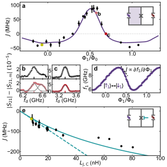
We have so far investigated the coupling strength at fixed gate voltages and flux. We now investigate the dependence of on different control parameters and demonstrate that it is tunable as predicted by Eq. (2) [5]. We vary using the flux line, see Fig. 4a, and find that the coupling strength is directly proportional to , as expected. The current difference across ASQ1, , is extracted from a measurement of the qubit frequency as a function of flux, as shown in Fig. 4d. Note that, by varying the flux, we not only vary the magnitude of , but also switch its sign, crossing zero coupling. Thus, the two ASQs can be fully uncoupled by setting at the flux points which maximize or minimize , and where thus , for either one of the qubits. The coinciding of zero coupling with these frequency-extrema is useful as these are the first-order flux-insensitive points of the qubit transition frequency. Two representative situations in which the ASQs are coupled and uncoupled at nearby flux points are shown in Fig. 4b and c, respectively. The data was measured and analyzed using the same procedure as described for Fig. 3.
We overlay the -dependence of the coupling strength with the expected dependence from Eq. 2. The values of and are fixed and independently extracted from measurements of the transmon frequency and of , respectively. is calculated as the parallel combination of the spin-independent Josephson inductances of both qubits, which are determined from separate transmon spectroscopy measurements (see Supplementary Information [16]) and is estimated from Fig. 4d. As shown in Fig. 4a, the measured is in good agreement with Eq. (2).
Finally, we investigate the tunability of by fixing , which sets , and varying the value of (see Supplementary Information for the corresponding qubit parameters [16]). We observe an increase of the magnitude of as the value of is increased, as shown in Fig. 4e. The measured data follows to a large extent the dependence expected from Eq. (2), indicated with a continuous line in Fig. 4e. The increase is limited to a maximum when the coupling junction becomes comparable to the finite spin-independent inductance of the ASQs. For the solid line in Fig. 4e we use the independently measured value . For comparison, the dashed line depicts the limit of .
V Conclusions
In conclusion, we have extended earlier results demonstrating single Andreev spin qubits [1, 2] and integrated two InAs/Al-based ASQs within a single transmon circuit. The two ASQs are separated by around , two orders of magnitude larger than the size of the individual qubit wavefunctions. Both ASQs showed comparable coherence properties to those reported in prior work [1, 2]. We have shown strong supercurrent-mediated coupling between the two Andreev spin qubits and found that the coupling strength, , can be tuned with either a magnetic flux or an electrical voltage. In particular, we have shown that can be fully suppressed using a magnetic flux. This switchability of the coupling is essential for the use of longitudinally coupled Andreev spin qubits to perform quantum computation. Furthermore, the high sign and magnitude tunability of could have applications for the use of Andreev spin qubits to perform analog quantum simulations. More generally, Andreev spin qubits could in the future provide an independent platform for quantum computing and simulation or, alternatively, they may be incorporated into existing spin qubit platforms and serve as readout modules or long-distance couplers. Independently of the precise use-case for Andreev spin qubits, we emphasize that strong spin-spin coupling as demonstrated here will be an essential requirement, although smaller dephasing rates would be desired.
Previous works suggest that one possible mechanism limiting dephasing is coupling to the large nuclear spins of InAs [36, 1, 2]. While the origin of dephasing must be further investigated, this suggests that a possible route to increase the dephasing times is implementing Andreev spin qubits in an alternative nuclear-spin-free material such as germanium [43, 44, 45, 46]. We expect that future efforts using alternative materials could both provide a path towards integration in more established semiconductor-based quantum architectures as well as strongly increased coherence times. If longer coherence times can be achieved, in combination with the strong qubit-qubit coupling demonstrated here, Andreev spin qubits will emerge as an encouraging platform for the realization of high-fidelity two-qubit gates between remote spins.
Acknowledgements.
We thank B. van Heck, A. Kou, G. de Lange, V. Fatemi, P. Kurilovich, S. Diamond, T. Connolly, H. Nho, C. Boettcher, V. Kurilovich and X. Xue for discussions and their feedback on this manuscript. We thank Y. Nazarov for insightful discussions. We further thank Peter Krogstrup for guidance in the material growth. This work is part of the research project ‘Scalable circuits of Majorana qubits with topological protection’ (i39, SCMQ) with project number 14SCMQ02, which is (partly) financed by the Dutch Research Council (NWO). It has further been supported by the Microsoft Quantum initiative. C.K.A. acknowledges support from the Dutch Research Council (NWO).Data availability
Data as well as processing and plotting scripts are available online at https://doi.org/10.4121/e10185d0-026e-480f-bbaa-3448c6e1b9a2.
Author contributions
J.J.W., M.P.V., and C.K.A. conceived the experiment. Y.L. developed and provided the nanowire materials. J.J.W, M.P.V., L.S. and A.B. prepared the experimental setup and data acquisition tools. L.S. deposited the nanowires. J.J.W, M.P.V. and A.B designed the device. J.J.W and M.P.V. fabricated the device, performed the measurements and analysed the data, with continuous feedback from L.S., A.B. and C.K.A. L.P.K. and C.K.A. supervised the work. J.J.W., M.P.V., and C.K.A. wrote the manuscript with feedback from all authors.
References
- Hays et al. [2021] M. Hays, V. Fatemi, D. Bouman, J. Cerrillo, S. Diamond, K. Serniak, T. Connolly, P. Krogstrup, J. Nygård, A. Levy Yeyati, A. Geresdi, and M. H. Devoret, Coherent manipulation of an andreev spin qubit, Science 373, 430 (2021).
- Pita-Vidal et al. [2023] M. Pita-Vidal, A. Bargerbos, R. Žitko, L. J. Splitthoff, L. Grünhaupt, J. J. Wesdorp, Y. Liu, L. P. Kouwenhoven, R. Aguado, B. van Heck, A. Kou, and C. K. Andersen, Direct manipulation of a superconducting spin qubit strongly coupled to a transmon qubit, Nature Physics 10.1038/s41567-023-02071-x (2023).
- Hays et al. [2020] M. Hays, V. Fatemi, K. Serniak, D. Bouman, S. Diamond, G. de Lange, P. Krogstrup, J. Nygård, A. Geresdi, and M. H. Devoret, Continuous monitoring of a trapped superconducting spin, Nat Phys 16, 10.1038/s41567-020-0952-3 (2020).
- Chtchelkatchev and Nazarov [2003] N. M. Chtchelkatchev and Y. V. Nazarov, Andreev quantum dots for spin manipulation, Phys Rev Lett 90, 10.1103/PhysRevLett.90.226806 (2003).
- Padurariu and Nazarov [2010] C. Padurariu and Y. V. Nazarov, Theoretical proposal for superconducting spin qubits, Phys Rev B 81, 10.1103/PhysRevB.81.144519 (2010).
- Loss and DiVincenzo [1998] D. Loss and D. P. DiVincenzo, Quantum computation with quantum dots, Phys Rev A 57, 10.1103/PhysRevA.57.120 (1998).
- Hanson et al. [2007] R. Hanson, L. P. Kouwenhoven, J. R. Petta, S. Tarucha, and L. M. K. Vandersypen, Spins in few-electron quantum dots, Rev Mod Phys 79, 10.1103/RevModPhys.79.1217 (2007).
- Vandersypen et al. [2017] L. M. K. Vandersypen, H. Bluhm, J. S. Clarke, A. S. Dzurak, R. Ishihara, A. Morello, D. J. Reilly, L. R. Schreiber, and M. Veldhorst, Interfacing spin qubits in quantum dots and donors—hot, dense, and coherent, npj Quantum Information 3, 34 (2017).
- Burkard et al. [2023] G. Burkard, T. D. Ladd, A. Pan, J. M. Nichol, and J. R. Petta, Semiconductor spin qubits, Rev. Mod. Phys. 95, 025003 (2023).
- Mi et al. [2018] X. Mi, M. Benito, S. Putz, D. M. Zajac, J. M. Taylor, G. Burkard, and J. R. Petta, A coherent spin–photon interface in silicon, Nature 555, 10.1038/nature25769 (2018).
- Samkharadze et al. [2018] N. Samkharadze, G. Zheng, N. Kalhor, D. Brousse, A. Sammak, U. C. Mendes, A. Blais, G. Scappucci, and L. M. K. Vandersypen, Strong spin-photon coupling in silicon, Science 359, 10.1126/science.aar4054 (2018).
- Landig et al. [2018] A. J. Landig, J. V. Koski, P. Scarlino, U. C. Mendes, A. Blais, C. Reichl, W. Wegscheider, A. Wallraff, K. Ensslin, and T. Ihn, Coherent spin–photon coupling using a resonant exchange qubit, Nature 560, 10.1038/s41586-018-0365-y (2018).
- Borjans et al. [2020] F. Borjans, X. G. Croot, X. Mi, M. J. Gullans, and J. R. Petta, Resonant microwave-mediated interactions between distant electron spins, Nature 577, 10.1038/s41586-019-1867-y (2020).
- Harvey-Collard et al. [2022] P. Harvey-Collard, J. Dijkema, G. Zheng, A. Sammak, G. Scappucci, and L. M. Vandersypen, Coherent spin-spin coupling mediated by virtual microwave photons, Phys. Rev. X 12, 10.1103/physrevx.12.021026 (2022).
- Yu et al. [2023] C. X. Yu, S. Zihlmann, J. C. Abadillo-Uriel, V. P. Michal, N. Rambal, H. Niebojewski, T. Bedecarrats, M. Vinet, É. Dumur, M. Filippone, B. Bertrand, S. De Franceschi, Y.-M. Niquet, and R. Maurand, Strong coupling between a photon and a hole spin in silicon, Nature Nanotechnology 10.1038/s41565-023-01332-3 (2023).
- [16] See Supplemental Material, which contains further details about the theoretical expression for the coupling strength, fabrication and experimental setup, device tuneup, and additional data.
- Tosi et al. [2019] L. Tosi, C. Metzger, M. Goffman, C. Urbina, H. Pothier, S. Park, A. Levy Yeyati, J. Nygård, and P. Krogstrup, Spin-Orbit splitting of Andreev states revealed by microwave spectroscopy, Physical Review X 9, 10.1103/physrevx.9.011010 (2019).
- Wesdorp et al. [2021] J. J. Wesdorp, L. Grünhaupt, A. Vaartjes, M. Pita-Vidal, A. Bargerbos, L. J. Splitthoff, P. Krogstrup, B. van Heck, and G. de Lange, Dynamical polarization of the fermion parity in a nanowire Josephson junction, arXiv e-prints (2021), 2112.01936 .
- Wesdorp et al. [2022] J. J. Wesdorp, F. J. Matute-Caňadas, A. Vaartjes, L. Grünhaupt, T. Laeven, S. Roelofs, L. J. Splitthoff, M. Pita-Vidal, A. Bargerbos, D. J. van Woerkom, P. Krogstrup, L. P. Kouwenhoven, C. K. Andersen, A. Levy Yeyati, B. van Heck, and G. de Lange, Microwave spectroscopy of interacting Andreev spins, arXiv e-prints (2022), arXiv:2208.11198 .
- Bargerbos et al. [2022] A. Bargerbos, M. Pita-Vidal, R. Žitko, L. J. Splitthoff, L. Grünhaupt, J. J. Wesdorp, Y. Liu, L. P. Kouwenhoven, R. Aguado, C. Kraglund Andersen, A. Kou, and B. van Heck, Spectroscopy of spin-split Andreev levels in a quantum dot with superconducting leads, arXiv e-prints , arXiv:2208.09314 (2022), arXiv:2208.09314 .
- Doh [2005] Y.-J. Doh, Tunable Supercurrent Through Semiconductor Nanowires, Science 309, 272 (2005).
- Koch et al. [2007] J. Koch, T. M. Yu, J. Gambetta, A. A. Houck, D. I. Schuster, J. Majer, A. Blais, M. H. Devoret, S. M. Girvin, and R. J. Schoelkopf, Charge-insensitive qubit design derived from the cooper pair box, Physical Review A 76, 10.1103/physreva.76.042319 (2007).
- Larsen et al. [2015] T. W. Larsen, K. D. Petersson, F. Kuemmeth, T. S. Jespersen, P. Krogstrup, J. Nygård, and C. M. Marcus, Semiconductor-nanowire-based superconducting qubit, Phys Rev Lett 115, 10.1103/PhysRevLett.115.127001 (2015).
- de Lange et al. [2015] G. de Lange, B. van Heck, A. Bruno, D. J. van Woerkom, A. Geresdi, S. R. Plissard, E. P. A. M. Bakkers, A. R. Akhmerov, and L. DiCarlo, Realization of microwave quantum circuits using hybrid superconducting-semiconducting nanowire Josephson elements, Phys Rev Lett 115, 10.1103/PhysRevLett.115.127002 (2015).
- Samkharadze et al. [2016] N. Samkharadze, A. Bruno, P. Scarlino, G. Zheng, D. P. DiVincenzo, L. DiCarlo, and L. M. K. Vandersypen, High-kinetic-inductance superconducting nanowire resonators for circuit QED in a magnetic field, Phys. Rev. Applied 5, 10.1103/PhysRevApplied.5.044004 (2016).
- Kroll et al. [2018] J. G. Kroll, W. Uilhoorn, K. L. van der Enden, D. de Jong, K. Watanabe, T. Taniguchi, S. Goswami, M. C. Cassidy, and L. P. Kouwenhoven, Magnetic field compatible circuit quantum electrodynamics with graphene josephson junctions, Nature Communications 9, 4615 (2018).
- Kroll et al. [2019] J. G. Kroll, F. Borsoi, K. L. van der Enden, W. Uilhoorn, D. de Jong, M. Quintero-Pérez, D. J. van Woerkom, A. Bruno, S. R. Plissard, D. Car, E. P. A. M. Bakkers, M. C. Cassidy, and L. P. Kouwenhoven, Magnetic-field-resilient superconducting coplanar-waveguide resonators for hybrid circuit quantum electrodynamics experiments, Phys. Rev. Applied 11, 10.1103/PhysRevApplied.11.064053 (2019).
- Pita-Vidal et al. [2020] M. Pita-Vidal, A. Bargerbos, C.-K. Yang, D. J. van Woerkom, W. Pfaff, N. Haider, P. Krogstrup, L. P. Kouwenhoven, G. de Lange, and A. Kou, Gate-tunable field-compatible fluxonium, Phys. Rev. Applied 14, 10.1103/PhysRevApplied.14.064038 (2020).
- Kringhøj et al. [2021] A. Kringhøj, T. W. Larsen, O. Erlandsson, W. Uilhoorn, J. Kroll, M. Hesselberg, R. McNeil, P. Krogstrup, L. Casparis, C. Marcus, and K. Petersson, Magnetic-field-compatible superconducting transmon qubit, Phys. Rev. Appl. 15, 054001 (2021).
- Uilhoorn et al. [2021] W. Uilhoorn, J. G. Kroll, A. Bargerbos, S. D. Nabi, C.-K. Yang, P. Krogstrup, L. P. Kouwenhoven, A. Kou, and G. de Lange, Quasiparticle trapping by orbital effect in a hybrid superconducting-semiconducting circuit, arXiv e-prints , arXiv:2105.11038 (2021), arXiv:2105.11038 [cond-mat.mes-hall] .
- Blais et al. [2004] A. Blais, R.-S. Huang, A. Wallraff, S. M. Girvin, and R. J. Schoelkopf, Cavity quantum electrodynamics for superconducting electrical circuits: An architecture for quantum computation, Phys Rev A 69, 10.1103/PhysRevA.69.062320 (2004).
- Note [1] In an ASQ, the spin is hybridized with spatial degrees of freedom, and thus the eigenstates are rather pseudo-spin states. Similar to previous works [1, 2], we will refer to the eigenstates as spins for simplicity.
- Metzger et al. [2021] C. Metzger, S. Park, L. Tosi, C. Janvier, A. A. Reynoso, M. F. Goffman, C. Urbina, A. L. Yeyati, and H. Pothier, Circuit-QED with phase-biased Josephson weak links, Phys. Rev. Research 3, 10.1103/physrevresearch.3.013036 (2021).
- Pavešić et al. [2022] L. Pavešić, M. Pita-Vidal, A. Bargerbos, and R. Žitko, Impurity knight shift in quantum dot josephson junctions, arXiv preprint arXiv:2212.07185 (2022).
- Vaitiekėnas et al. [2018] S. Vaitiekėnas, M.-T. Deng, J. Nygård, P. Krogstrup, and C. M. Marcus, Effective factor of subgap states in hybrid nanowires, Phys. Rev. Lett. 121, 037703 (2018).
- Nadj-Perge et al. [2010] S. Nadj-Perge, S. M. Frolov, E. P. A. M. Bakkers, and L. P. Kouwenhoven, Spin–orbit qubit in a semiconductor nanowire, Nature 468, 10.1038/nature09682 (2010).
- Spethmann et al. [2022] M. Spethmann, X.-P. Zhang, J. Klinovaja, and D. Loss, Coupled superconducting spin qubits with spin-orbit interaction, Phys. Rev. B 106, 115411 (2022).
- Rol et al. [2020] M. A. Rol, L. Ciorciaro, F. K. Malinowski, B. M. Tarasinski, R. E. Sagastizabal, C. C. Bultink, Y. Salathe, N. Haandbaek, J. Sedivy, and L. DiCarlo, Time-domain characterization and correction of on-chip distortion of control pulses in a quantum processor, Applied Physics Letters 116, 054001 (2020), https://pubs.aip.org/aip/apl/article-pdf/doi/10.1063/1.5133894/14531145/054001_1_online.pdf .
- Arute et al. [2019] F. Arute, K. Arya, R. Babbush, D. Bacon, J. C. Bardin, R. Barends, R. Biswas, S. Boixo, F. G. S. L. Brandao, D. A. Buell, B. Burkett, Y. Chen, Z. Chen, B. Chiaro, R. Collins, W. Courtney, A. Dunsworth, E. Farhi, B. Foxen, A. Fowler, C. Gidney, M. Giustina, R. Graff, K. Guerin, S. Habegger, M. P. Harrigan, M. J. Hartmann, A. Ho, M. Hoffmann, T. Huang, T. S. Humble, S. V. Isakov, E. Jeffrey, Z. Jiang, D. Kafri, K. Kechedzhi, J. Kelly, P. V. Klimov, S. Knysh, A. Korotkov, F. Kostritsa, D. Landhuis, M. Lindmark, E. Lucero, D. Lyakh, S. Mandrà, J. R. McClean, M. McEwen, A. Megrant, X. Mi, K. Michielsen, M. Mohseni, J. Mutus, O. Naaman, M. Neeley, C. Neill, M. Y. Niu, E. Ostby, A. Petukhov, J. C. Platt, C. Quintana, E. G. Rieffel, P. Roushan, N. C. Rubin, D. Sank, K. J. Satzinger, V. Smelyanskiy, K. J. Sung, M. D. Trevithick, A. Vainsencher, B. Villalonga, T. White, Z. J. Yao, P. Yeh, A. Zalcman, H. Neven, and J. M. Martinis, Quantum supremacy using a programmable superconducting processor, Nature 574, 10.1038/s41586-019-1666-5 (2019).
- Rol et al. [2019] M. A. Rol, F. Battistel, F. K. Malinowski, C. C. Bultink, B. M. Tarasinski, R. Vollmer, N. Haider, N. Muthusubramanian, A. Bruno, B. M. Terhal, and L. DiCarlo, Fast, high-fidelity conditional-phase gate exploiting leakage interference in weakly anharmonic superconducting qubits, Phys. Rev. Lett. 123, 120502 (2019).
- He et al. [2019] Y. He, S. K. Gorman, D. Keith, L. Kranz, J. G. Keizer, and M. Y. Simmons, A two-qubit gate between phosphorus donor electrons in silicon, Nature 571, 371 (2019).
- Hendrickx et al. [2021] N. W. Hendrickx, W. I. L. Lawrie, M. Russ, F. Van Riggelen, S. L. De Snoo, R. N. Schouten, A. Sammak, G. Scappucci, and M. Veldhorst, A four-qubit germanium quantum processor, Nature 591, 580 (2021).
- Hendrickx et al. [2018] N. W. Hendrickx, D. P. Franke, A. Sammak, M. Kouwenhoven, D. Sabbagh, L. Yeoh, R. Li, M. L. V. Tagliaferri, M. Virgilio, G. Capellini, G. Scappucci, and M. Veldhorst, Gate-controlled quantum dots and superconductivity in planar germanium, Nat Commun 9, 10.1038/s41467-018-05299-x (2018).
- Scappucci et al. [2021] G. Scappucci, C. Kloeffel, F. A. Zwanenburg, D. Loss, M. Myronov, J.-J. Zhang, S. De Franceschi, G. Katsaros, and M. Veldhorst, The germanium quantum information route, Nat. Rev. Mater. 6, 10.1038/s41578-020-00262-z (2021).
- Tosato et al. [2023] A. Tosato, V. Levajac, J.-Y. Wang, C. J. Boor, F. Borsoi, M. Botifoll, C. N. Borja, S. Martí-Sánchez, J. Arbiol, A. Sammak, M. Veldhorst, and G. Scappucci, Hard superconducting gap in germanium, Communications Materials 4, 23 (2023).
- Valentini et al. [2023] M. Valentini, O. Sagi, L. Baghumyan, T. de Gijsel, J. Jung, S. Calcaterra, A. Ballabio, J. Aguilera Servin, K. Aggarwal, M. Janik, T. Adletzberger, R. Seoane Souto, M. Leijnse, J. Danon, C. Schrade, E. Bakkers, D. Chrastina, G. Isella, and G. Katsaros, Radio frequency driven superconducting diode and parity conserving Cooper pair transport in a two-dimensional germanium hole gas, arXiv e-prints , arXiv:2306.07109 (2023), arXiv:2306.07109 [cond-mat.mes-hall] .