Nonlinear optical diode effect in a magnetic Weyl semimetal
I Abstract
Weyl semimetals have emerged as a promising quantum material system to discover novel electrical and optical phenomena, due to their combination of nontrivial quantum geometry and strong symmetry breaking. One crucial class of such novel transport phenomena is the diode effect, which is of great interest for both fundamental physics and modern technologies. In the electrical regime, giant electrical diode effect (the nonreciprocal transport) has been observed in Weyl systems. In the optical regime, novel optical diode effects have been theoretically considered but never probed experimentally. Here, we report the observation of the nonlinear optical diode effect (NODE) in the magnetic Weyl semimetal CeAlSi, where the magnetic state of CeAlSi introduces a pronounced directionality in the nonlinear optical second-harmonic generation (SHG). By physically reversing the beam path, we show that the measured SHG intensity can change by at least a factor of six between forward and backward propagation over a wide bandwidth exceeding . Supported by density-functional theory calculations, we establish the linearly dispersive bands emerging from Weyl nodes as the origin of the extreme bandwidth. Intriguingly, the NODE directionality is directly controlled by the direction of magnetization. By utilizing the electronically conductive semimetallic nature of CeAlSi, we demonstrate current-induced magnetization switching and thus electrical control of the NODE in a mesoscopic spintronic device structure with current densities as small as . Our results advance ongoing research to identify novel nonlinear optical/transport phenomena in magnetic topological materials. The NODE also provides a way to measure the phase of nonlinear optical susceptibilities and further opens new pathways for the unidirectional manipulation of light such as electrically controlled optical isolators.
II Main
Diode effects, i.e., phenomena that exhibit a preferred direction, are at the heart of new fundamental physics and modern technologies. A primary example is an electrical diode, which readily conducts current in one direction, but has a high resistance in the opposite direction. In analogy to electrical diodes, optical diodes are characterized by a directionally asymmetric propagation of light. Recent theoretical studies have shown that such an optical diode effect can reveal fundamentally new physics, such as the quantum metric of Bloch wavefunctions 1, 2, 3. Moreover, the optical diode would be a crucial component of various optical technologies including the photonics, where light instead of electrical current is envisioned as information carrier. For instance, in the microwave regime, the optical diode effect has been proposed for telecommunications 4, 5. Such prospects have inspired a flurry of experimental studies of the optical diode effect (also known as the nonreciprocal directional dichroism) especially in magnetoelectric wide-bandgap insulators 6, 7. However, the observed optical diode effect is typically very weak with the difference between forward and backward propagation being less than 1% unless the photon energy is tuned to specific narrow electronic or magnetic resonances with bandwidths often below .
In addition to its propagation direction, light has another important degree of freedom, the color (frequency). Therefore, it is possible to conceptualize the nonlinear optical diode effect, where the photon frequency changes during the diode process. A second-order diode effect is a process where the optical second-harmonic generation (SHG) of a material along the forward and backward propagation directions differ. In terms of fundamental physics, the nonlinear optical diode effect (NODE) may reveal novel quantum geometrical phenomena distinct from the linear optical diode 8, 9, 10, 11. Also, nonlinear optical processes (e.g. SHG) can lead to a much stronger diode effect (i.e., a larger contrast between the forward and backward direction) as SHG supports much stronger crystallographic selection rules 12, 13. In terms of technology, the NODE may also enable novel optical applications such as unidirectional and mode-locked lasers 14 and novel designs for optical isolators for optical communication 15.
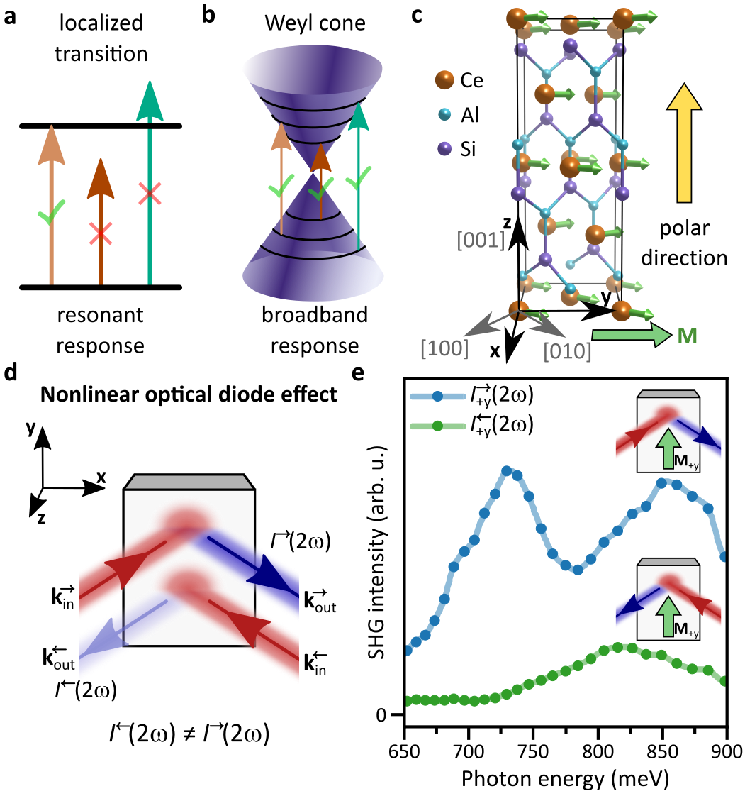
Recently, Weyl semimetals have emerged as an attractive system to explore various novel electrical and optical phenomena, due to its combination of nontrivial quantum geometry and strong symmetry breaking (to generate Weyl fermions, the system has to break space-inversion, or time-reversal, or both). In the electrical regime, a giant electrical diode effect (the nonreciprocal transport) has been observed in Weyl systems 16. In the optical regime, novel optical diode effect has been theoretically considered 1, 2, 17 but never probed experimentally. In contrast to conventional magnetoelectric insulators 12, 13 (Fig. 1a), the Weyl semimetals host linearly dispersive Weyl cones, which can allow for a wide range of photon energies to excite interband optical transitions in the material (Fig. 1b).
In this paper, we report the observation and manipulation of a giant, broadband NODE in the magnetic Weyl semimetal CeAlSi. We demonstrate that at least a sixfold change in SHG intensity is achievable between forward and backward propagating light over a broad spectral range covering . Supported by first-principles calculations, we establish a link between the broadband characteristics and the linearly dispersive Weyl fermions in CeAlSi. We show that the directionality of the NODE is directly related to the magnetic order in CeAlSi. We can switch the magnetic order by passing a current and thus demonstrate electrical control of the NODE. We reveal that this basic opto-spintronic functionality persists in technologically relevant, micromachined device structures with the additional advantage of drastically reduced switching currents.
III Observation of the nonlinear optical diode effect (NODE) in CeAlSi
CeAlSi belongs to the family of Weyl semimetals with chemical formula Al ( and =Si or Ge) that recently gained considerable attention as magnetic Weyl semimetals18, 19, 20, 21, 22, 23, 24, 25, 26, 27, 28, 29. This family is closely related to TaAs 30, 31, as they have the same noncentrosymmetric, tetragonal crystal structure (point group ) and the same valence condition ( ). The introduction of magnetic rare earth elements (Ce, Pr, or Nd) in Al compounds leads to long-range magnetic order. Depending on the rare earth element, a variety of magnetic structures ranging from simple collinear ferromagnetism to noncollinear magnetism and complex multi- helical spin structures has been found 19, 20, 21, 22, 23, 24, 25. The interplay between Weyl fermions, inversion symmetry-breaking, and magnetism provides a fertile ground to discover novel emergent quantum electromagnetism in this class of Weyl semimetals.
CeAlSi exhibits a canted ferromagnetic order below (Fig. 1c). The net magnetization points along one of the four symmetry-equivalent in-plane crystallographic directions, and (We define , , and , Fig. 1c). Hence, there are four distinct ferromagnetic states, denoted as , , , and . Such a -breaking magnetic ordering on a -breaking crystal structure makes CeAlSi a promising candidate for the observation of the NODE.
We consider the NODE explicitly by experimentally reversing the light path. As CeAlSi is semimetallic and therefore highly reflective, we consider the NODE here in a reflection geometry (Fig. 1d). We study in particular SHG from the facet of a CeAlSi single crystal. Therefore, all four magnetic states of CeAlSi exhibit an in-plane net magnetization. We orient the crystal such that the s-polarization of light is parallel to the net magnetization of two out of the four possible magnetic states. We denote those states as states and the states with net magnetization perpendicular to the s-polarization states (see coordinate system in Fig. 1d).
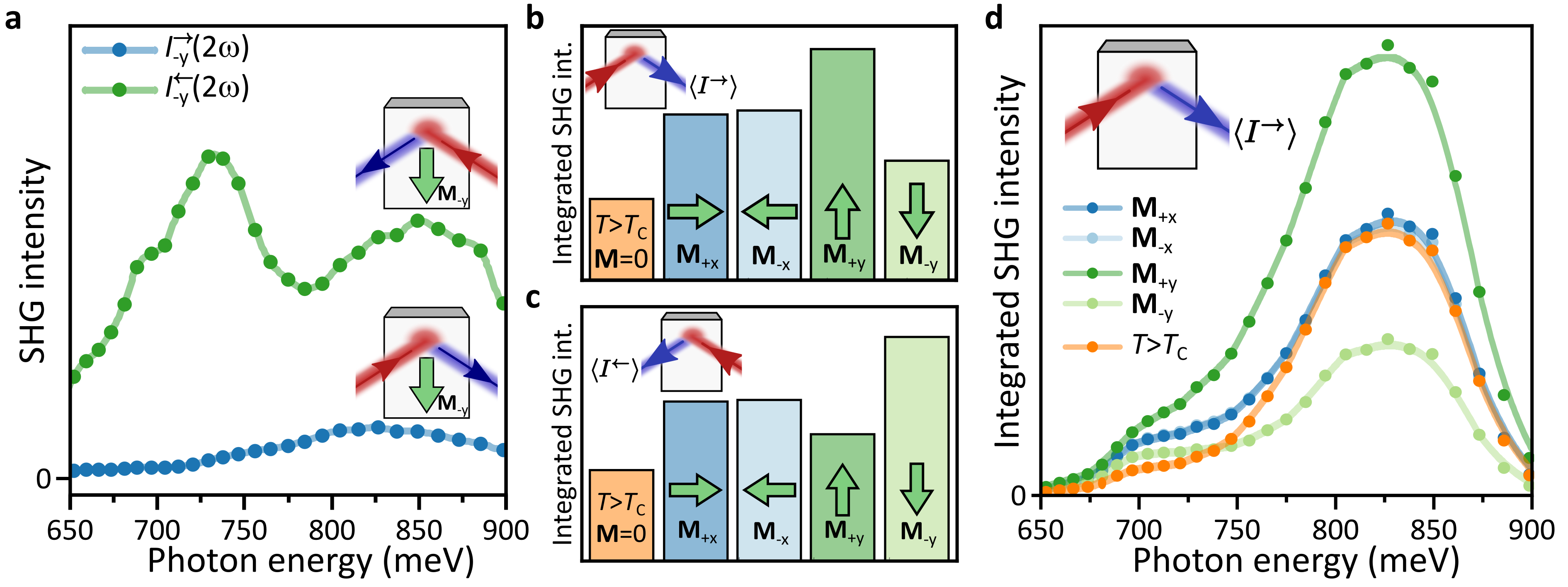
In Fig. 1e, we directly compare the spectra for the recorded SHG intensity for the forward propagation direction () and the backward propagation direction () for the magnetic state. The SHG intensity in forward direction is more than twice as large as the intensity in backward direction over the entire considered spectral range of the incident light from to . Reversing the magnetization reverses the situation (Extended Data Fig. 1a). We thus find that the SHG response exhibits a NODE over a wide range of fundamental photon energies spanning at least .
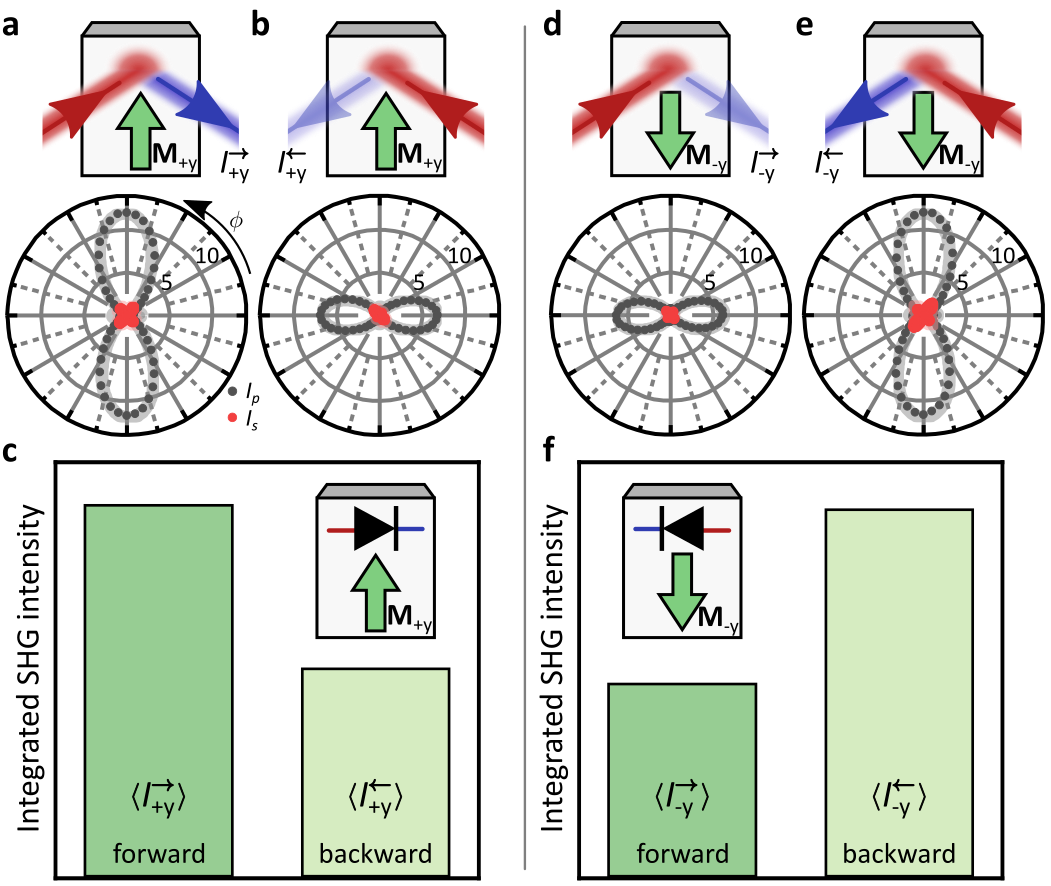
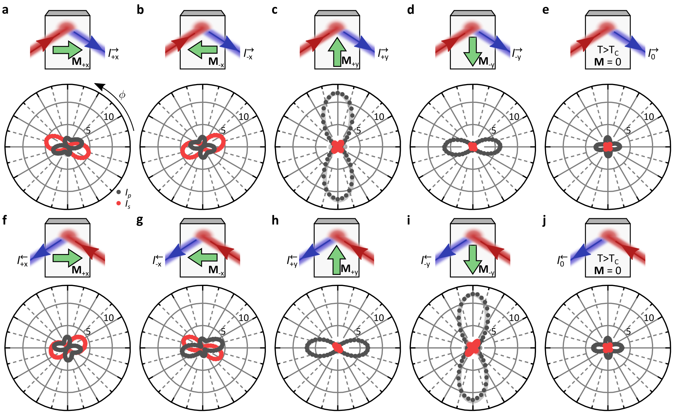
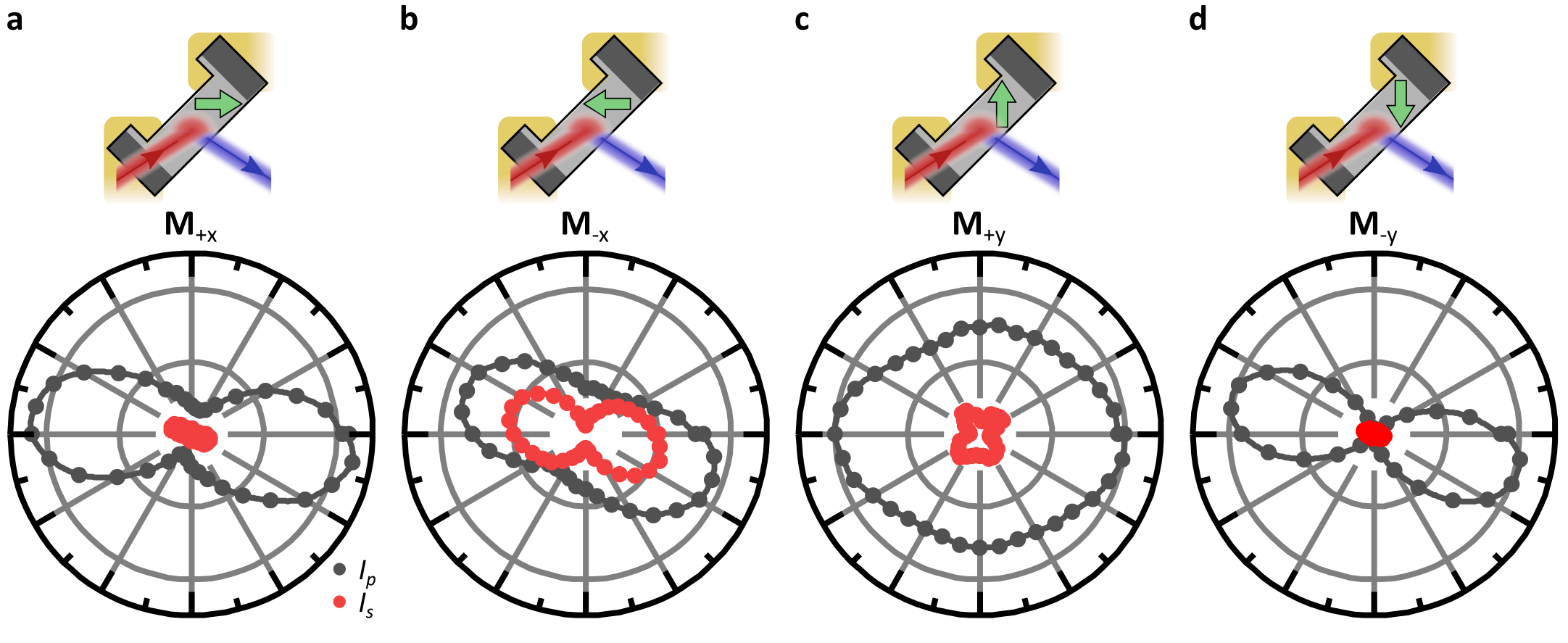
In Figs. 2a,b we show the polarization dependence of and , respectively, at a fundamental photon energy of for the magnetic state of CeAlSi. The polarization dependence also clearly reveals the NODE in the SHG response. To further corroborate the nonreciprocal character of the observed SHG, we define the integrated SHG intensity as the intensity measured without polarization analysis, thus simultaneously detecting s- and p-polarized SHG light, and averaging over all polarizations of the incident fundamental light. Comparing the integrated SHG intensity between the forward and backward direction gives us a measure of the diode effect independent of the light polarization (i.e., the diode effect for unpolarized light). Interestingly, we find for the magnetic state that the integrated SHG intensity in the forward direction is significantly higher than in the reversed direction (Fig. 2c). This shows that the NODE is not restricted to particular polarization configurations but a net diode effect can persist even in the case of unpolarized incident light.
IV Magnetic control of the NODE
Interestingly, the directionality of the NODE can be controlled by the magnetic order. In Figs. 2a-c and 2d-e, we compare the results for the and states, from which we see that the directionality of the NODE is flipped as we flip the magnetization. Thus, while the broken symmetry in general activates the NODE, the broken symmetry enables controlling its directionality. By selecting either the or state, we can deterministically set the propagation direction that generates higher integrated SHG intensity.
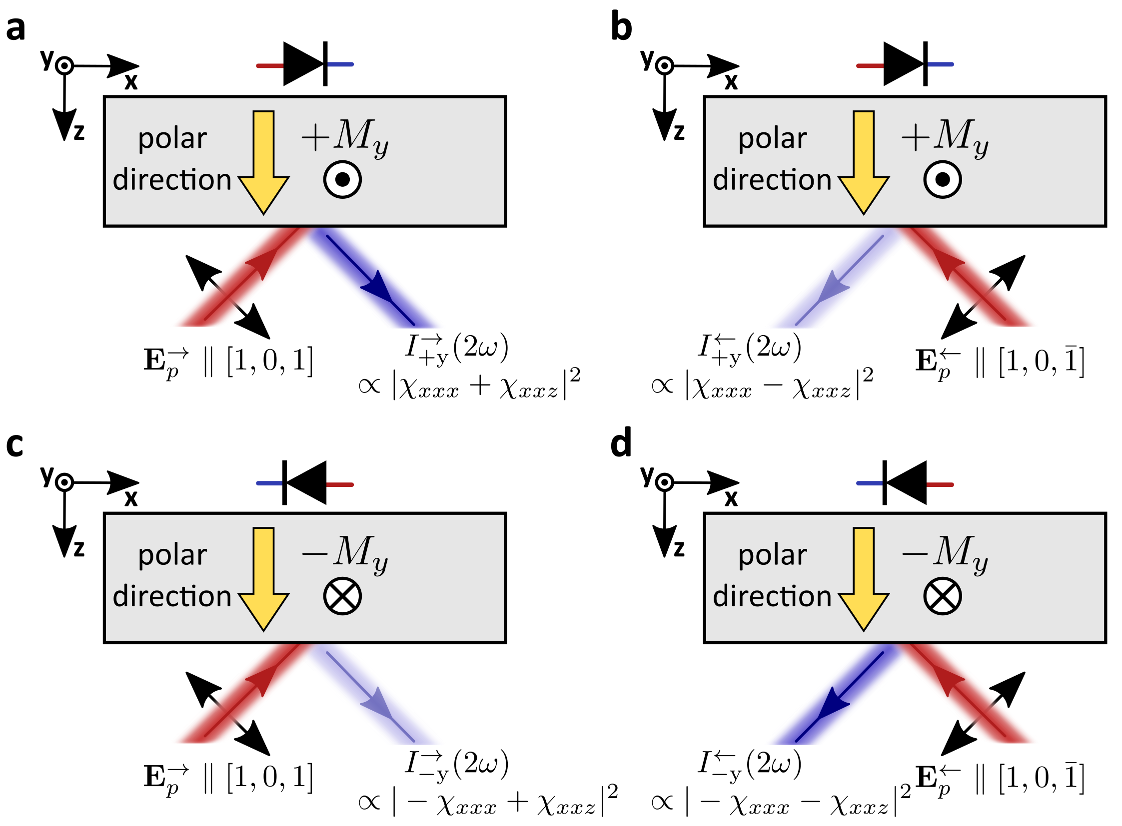
We can understand the NODE and its magnetic control by the interference of independent SHG tensor components with different origins. In our case, we can use and . arises from the noncentrosymmetric polar lattice of CeAlSi; arises from the magnetic order. As shown in Extended Data Fig. 4, the total SHG intensity is given by . Considering p-polarized incident light, the electric field of the light wave is parallel to leading to a dependence of the SHG response. Specifically, as we reverse the light propagation direction, we reverse the relative sign between and . Hence, we find and . Thus, the NODE is based on a directionally dependent mixing between tensor components. It is interesting to note that the origin of the symmetry breaking that enables those tensor components is not crucial. This is in contrast to the established SHG interference imaging technique which strictly relies on interference between order-parameter dependent and order-parameter independent tensor components 32. As a consequence, a NODE can in principle exist even in non-magnetic materials. Here, however, we explicitly utilize the different origin of and to control the directionality of the NODE. As we reverse the magnetization direction, we reverse the sign of the magnetic SHG tensor but the crystalline SHG tensor component remains unchanged. Thus, we find and , which explains why the NODE directionality flips as we flip the magnetization direction.
V Electrical control of the NODE
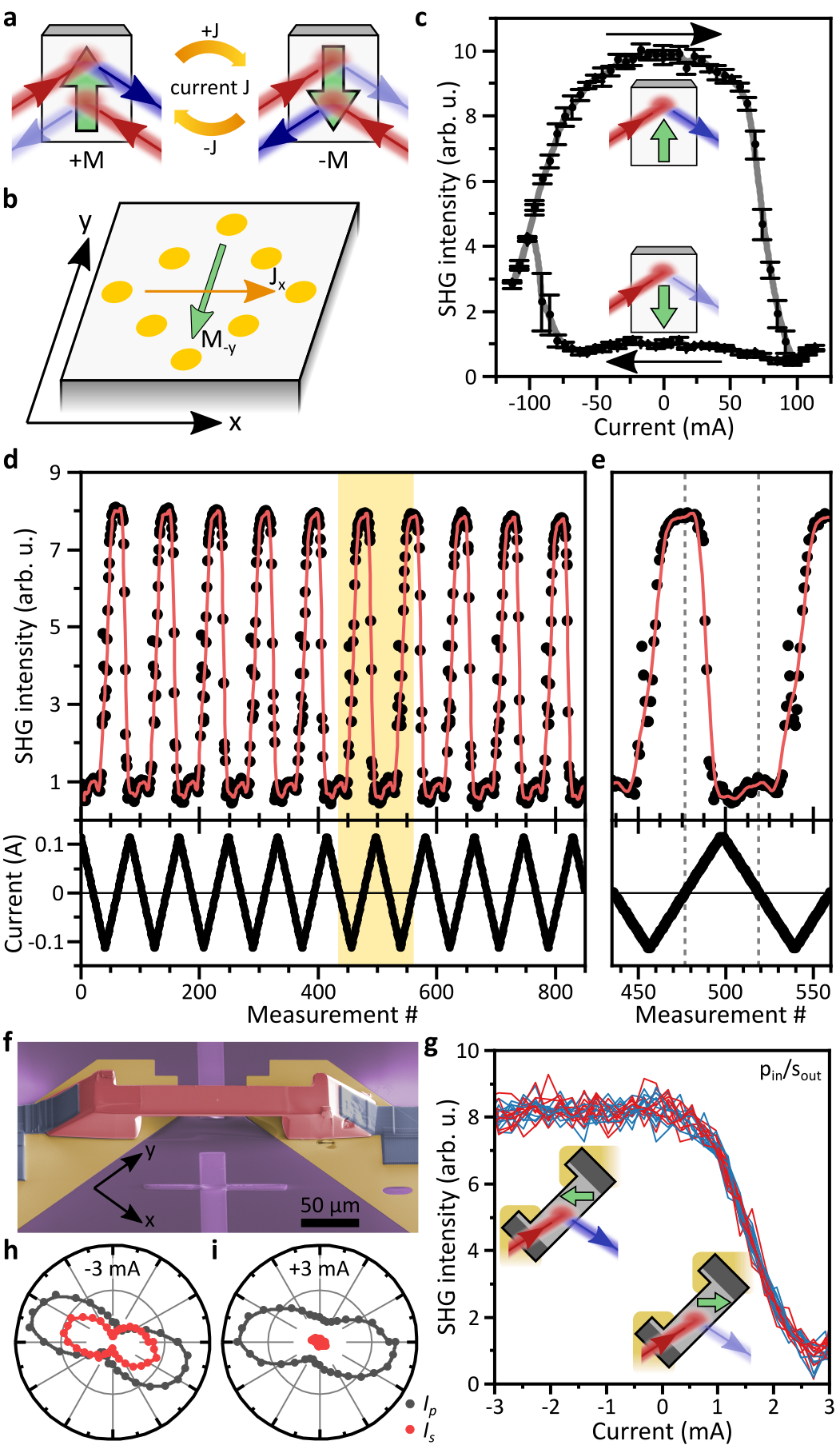
The noncentrosymmetric symmetry of CeAlSi supports a magnetoelectric coupling between the magnetization and a current . Microscopically, such a coupling may be either intrinsic 33, 34, mediated by strain 35, or relying on the spin-Hall effect36 and assisted by the Oersted field of the current 37, 38. In all cases, the magnetoelectric coupling is such that a current in the -plane favors a magnetization perpendicular to the current in the -plane with a fixed handedness as depicted in Fig. 3b, providing a way to control the magnetic domain configuration through an electrical current.
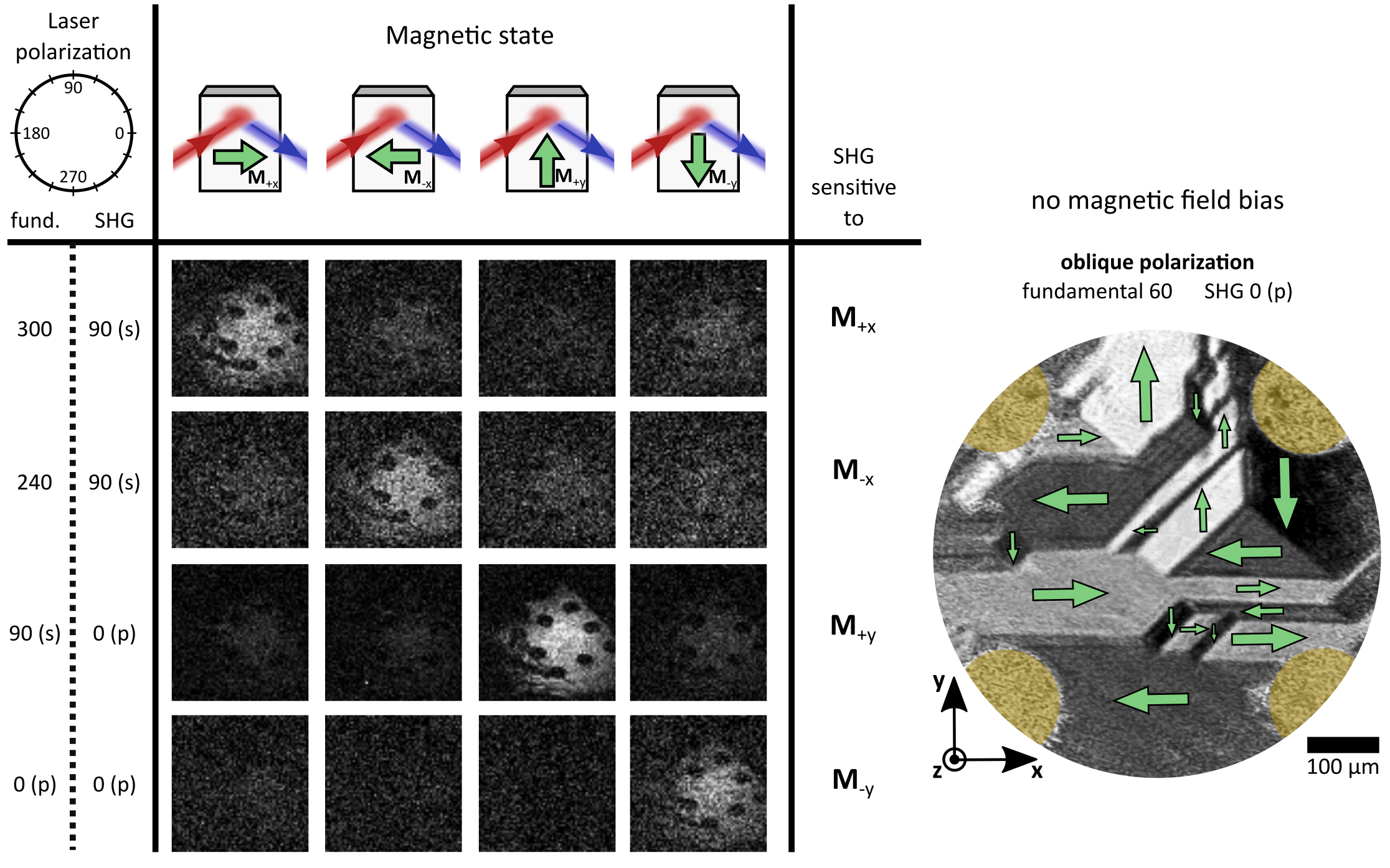
We supply a current in the -plane through a pattern of gold electrodes on a facet of the sample as illustrated in Fig. 3b. We can then use SHG to optically detect the magnetization state. Specifically, we choose s-polarized incident light at and detect p-polarized SHG, where states correspond to high and low SHG intensity, respectively (Fig. 2a,b. See also Extended Data Fig. 5 for more systematic characterizations).
Remarkably, we find that passing a current in CeAlSi can directly choose its magnetization direction. Moreover, the selected magnetization persists when the current is removed (i.e., the control is nonvolatile). Specifically, as shown in Fig. 3c, if we pass a negative current of along the -direction and then remove this current, we control the magnetization to be along (); if we pass a positive current of and then remove this current, we control the magnetization to be along (). Therefore, the data in Fig. 3c shows that the magnetization of CeAlSi can be controlled by current. Moreover, Fig. 3d shows the results over the course of consecutive current cycles along opposite directions. We found that the control is highly deterministic, i.e., current selects magnetization whereas current selects magnetization. The control is also clearly nonvolatile, i.e., the selected magnetization persists when the current is reduced to zero. By electrically controlling the NODE, we realize here a basic nonreciprocal nonlinear opto-spintronic functionality.
We note that the above results are obtained on a large mm-sized single crystal. So although the total current needed for the magnetic control appears large (), the current density is very small. However, as the contacts are deposited on the top surface (Fig. 3b), the spatial distribution of current flow is likely to be inhomogeneous for such a thick bulk crystal (especially along the direction), so it is hard to reliably estimate the current density. In order to reliably estimate the current density, it is highly desirable to fabricate a miniaturized device. Such a micro-device also helps us to explore the tantalizing potential of electrically controlling the nonlinear optical response of CeAlSi for spintronic applications.
In Fig. 3f, we use focused ion-beam (FIB) milling to fabricate such a micro-device of CeAlSi. The core part of the structure is a free-standing slab of CeAlSi of . In order to counter-act the significant magnetic shape anisotropy due to the large aspect ratio and keep the device switchable, we prepared the slab with the long axis along the magnetic hard axis, i.e. at an angle of relative to the and directions. The device can be poled into a magnetic single domain state with magnetic fields of about . Analogously to the previous bulk measurements, the four magnetic states can be distinguished by their SHG polarization dependence (Extended Data Fig. 7).
Most strikingly, in the absence of external magnetic fields, we can electrically control the magnetic state of the micro-device with dramatically reduced currents. As shown in Fig. 3g, we find that we can change the magnetic state in the FIB device with currents as small as corresponding to current densities of around in the slab (in this case, we do not see remanent switching possibly due to shape anisotropy and residual strain in the sample 39, 40, 35). The magnetic switching is clearly evidenced by a change of the SHG polarization dependence indicative of switching between the state at and a state at . Such a reversible electrical control of a magnetic state may be highly desirable for novel device concepts.
VI Observation of a broadband NODE
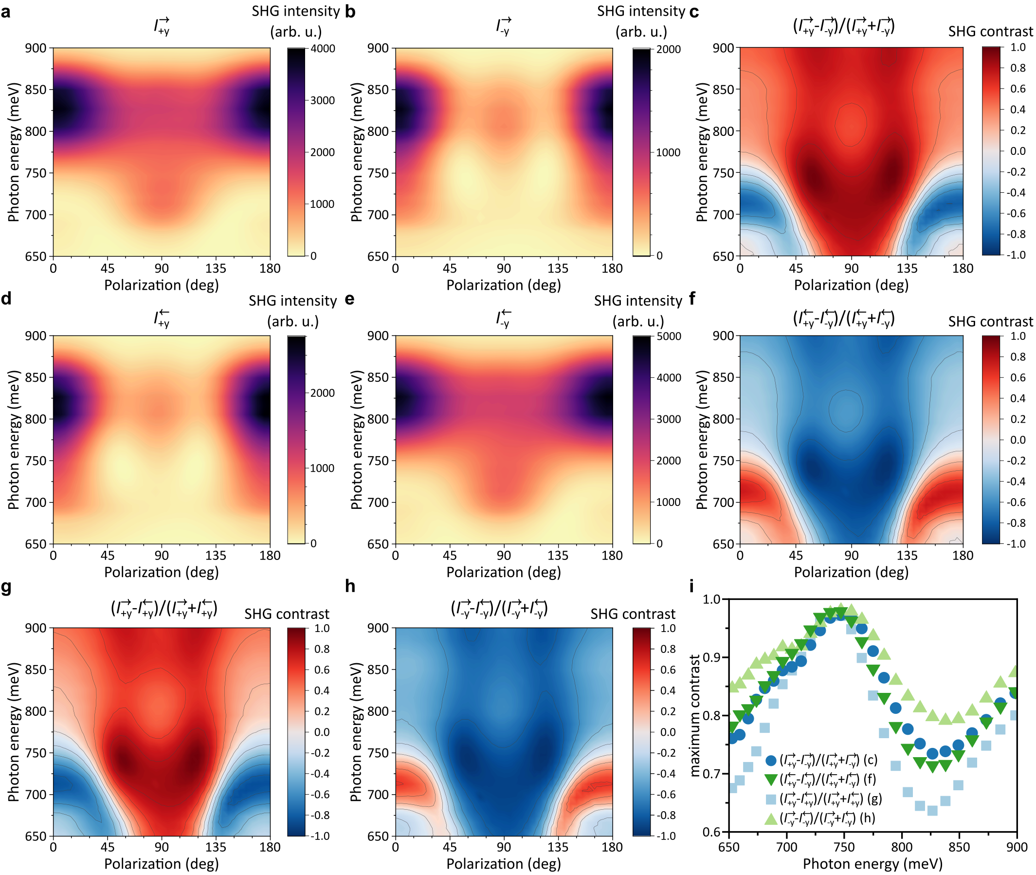
Note that so far we observed a pronounced NODE for a specific SHG component at without deliberate optimization with respect to polarization or photon energy. However, a comparison of Figs. 2a and b reveals that changing the magnetization induces large changes of SHG intensity for certain polarization components and vanishing changes for others. To quantify the NODE, we define the nonreciprocal contrast as
| (1) |
The nonreciprocal contrast corresponds to absence of the NODE (i.e., the SHG intensity along forward and backward directions is equal); the nonreciprocal contrast corresponds to extreme NODE (i.e., SHG can only occur along one direction)
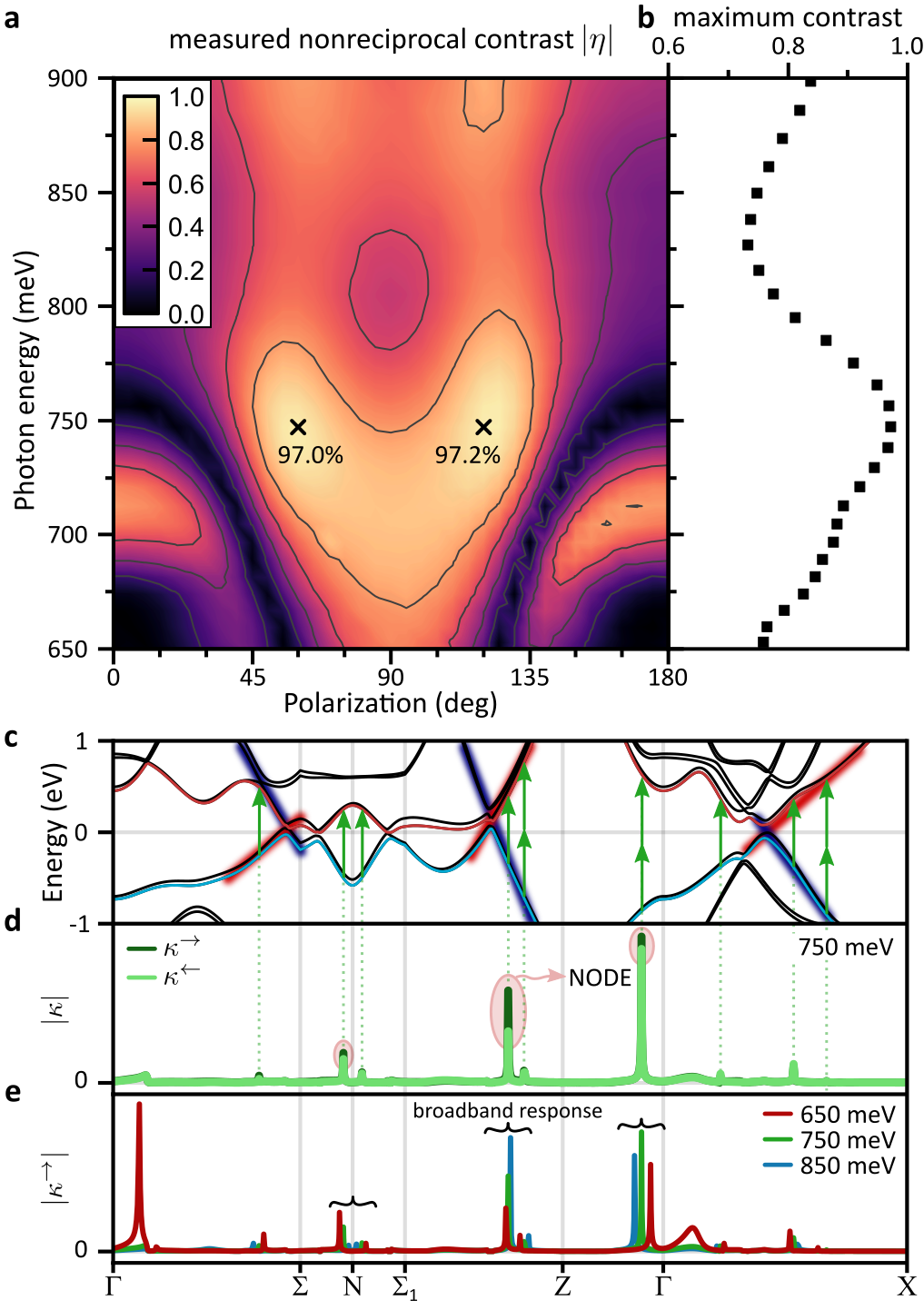
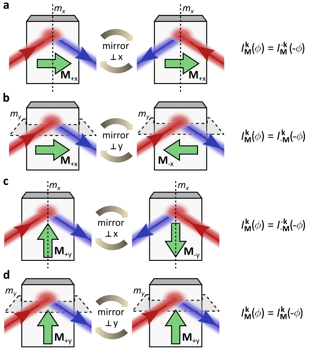
In Fig. 4a, we show the evolution of for p-polarized SHG as a function of both incoming laser polarization and SHG photon energy. Here, we compare and , which is equivalent to comparing and but experimentally more straightforwardly accessible (see Extended Data Fig. 6 for other assessments of ). The figure is characterized by a rich behavior that is mirror symmetric along the 0 and 90 deg directions due to mirror symmetries in CeAlSi. At we find that exhibits maxima at 0 deg/180 deg (p-polarized light) as well as near 90 deg (s-polarized light) but vanishes near 45/135 deg, in agreement with Fig. 2a and b. In Fig. 4b, we show the maximum achievable contrast for each SHG photon energy. The nonreciprocal contrast peaks around at corresponding to a more than 70-fold change in SHG intensity. Moreover, we find that a nonreciprocal contrast of at least (corresponding to a more than 6-fold change) is achievable for all photon energies in the considered spectral range between and .
VII Broadband NODE from first principles
In order to understand the microscopic origin of the NODE, we directly compute the NODE from the electronic structure of CeAlSi. Specifically, the NODE is the difference in SHG intensity between opposite propagation directions, which is determined by the two momentum-space resolved quantities and as (see methods, Eq. (8)):
| (2) |
Here, , where is the electric field of the incident light for the forward and backward propagation direction, is a projector to select either the or polarized SHG response, and is the k-space resolved contribution to the nonlinear optical susceptibility ( is directly computed from the band structure of CeAlSi, see methods Eqs. (5) and (6)).
Figure 4c shows a section of the band structure of CeAlSi consistent with previous first-principles calculations 22 (see methods for further details). Along with the band structure, we show in Fig. 4d the magnitude of and in the band structure of CeAlSi (for ). We see from Fig. 4d that discrete points contribute significantly. By comparing Figs. 4c and d, it is clear that these are the states which allow for optical transitions at or across the Fermi energy. Importantly, the magnitude of and differs significantly, giving rise to the observed NODE.
To understand the band structure origin of the broadband nature of the NODE in CeAlSi, we vary the incident photon energy from to . We can observe two qualitatively different behaviors (Fig. 4e). On the one hand, we notice a few contributions such as near the point along the line that occur only at specific photon energies (here ). The bands at that point are relatively flat. As the photon energy changes, such contributions disappear, which is indicative of a typical electronic resonance. Despite the apparent size of this resonant contribution, the spectrum of all SHG tensor components evolves smoothly towards indicating an overall negligible effect (Ext. Data Fig. 8). On the other hand, the majority of the SHG response arises at points where the electronic bands are linearly dispersive. Accordingly, as we vary the incident photon energy, those contributions only shift slightly to different points but remain comparable in magnitude. This observation of SHG originating from linearly dispersive bands is qualitatively different from the conventional resonance picture. Moreover, we thus see that the broadband NODE in CeAlSi ultimately arises from the linearly dispersive bands in the vicinity of the Weyl nodes.
VIII Discussion
In summary, we explored the nonlinear optical response of the magnetic Weyl semimetal CeAlSi using SHG spectroscopy. In addition to the crystallographic (time-reversal symmetric) SHG, we observe magnetic (time-reversal asymmetric) SHG, which represents the first observation of magnetic SHG in a topologically nontrivial material. By physically reversing the light path, we revealed a pronounced NODE. Specifically, we found a sizable nonreciprocal contrast of at least over a remarkable spectral range exceeding — two orders of magnitude wider than previous reports.
Microscopically, our DFT calculations show that the extreme broadband NODE is directly related to the electronic band structure. The SHG response emerges from linearly dispersive bands that naturally occur near the Fermi energy in a Weyl semimetal. The linear dispersion allows for strong optical responses over a wide range of frequencies.
Our observations open up a number of intriguing possibilities. First, it suggests the NODE as a powerful method to measure the phase of optical properties. All optical processes (e.g., SHG, Raman) are governed by the corresponding susceptibility tensor, which is determined by the material. Hence, inversely, by measuring the SHG, Raman, or other optical process, we can learn about the symmetry and electronic properties of a material. However, typically we only access the magnitude of the susceptibility, whereas the sign or phase is hard to probe. Here, as we showed above, the NODE arises from the directionally dependent mixing between tensor components which provides insights into their relative phases. It would be interesting to test the optical diode effect for other optical processes such as high-harmonic generation 41, Raman scattering 42, and optically generated spin currents 43, where interesting phenomena hinting nonreciprocity have been observed. Second, we note the low current density associated with the switching of magnetic order in CeAlSi. It would be of interest to perform future studies to understand its microscopic mechanism and to test it on other magnetic and noncentrosymmetric Weyl fermion systems. The low-current switching in combination with the extreme broadband character of the NODE, may enable fundamentally new device concepts for photonic circuits. From a fundamental point of view, our observation of a broadband NODE is testament to the exotic electromagnetic responses that can be discovered in novel quantum magnets.
References
- [1] M. F. Lapa, T. L. Hughes, Semiclassical wave packet dynamics in nonuniform electric fields, Phys. Rev. B 99, 121111 (2019).
- [2] Y. Gao, D. Xiao, Nonreciprocal Directional Dichroism Induced by the Quantum Metric Dipole, Phys. Rev. Lett. 122, 227402 (2019).
- [3] Y. Zhang, L. Shi, C. T. Chan, K. H. Fung, K. Chang, Geometrical Theory of Electromagnetic Nonreciprocity, Phys. Rev. Lett. 130, 203801 (2023).
- [4] A. Sabharwal, et al., In-Band Full-Duplex Wireless: Challenges and Opportunities, IEEE J. Sel. Areas Commun. 32, 1637 (2014).
- [5] N. Reiskarimian, H. Krishnaswamy, Magnetic-free non-reciprocity based on staggered commutation, Nat. Commun. 7 (2016).
- [6] M. Fiebig, Revival of the magnetoelectric effect, J. Phys. D: Appl. Phys. 38, R123 (2005).
- [7] N. A. Spaldin, R. Ramesh, Advances in magnetoelectric multiferroics, Nat. Mater. 18, 203 (2019).
- [8] N. Nagaosa, T. Morimoto, Y. Tokura, Transport, magnetic and optical properties of Weyl materials, Nat. Rev. Mater. 5, 621 (2020).
- [9] J. Orenstein, et al., Topology and Symmetry of Quantum Materials via Nonlinear Optical Responses, Annu. Rev. Condens. Matter Phys 12, 247 (2021).
- [10] Q. Ma, A. G. Grushin, K. S. Burch, Topology and geometry under the nonlinear electromagnetic spotlight, Nat. Mater. 20, 1601 (2021).
- [11] N. Nagaosa, Nonlinear optical responses in noncentrosymmetric quantum materials, Ann. Phys. 169146 (2022).
- [12] S. Toyoda, M. Fiebig, T. hisa Arima, Y. Tokura, N. Ogawa, Nonreciprocal second harmonic generation in a magnetoelectric material, Sci. Adv. 7 (2021).
- [13] J. Mund, et al., Toroidal nonreciprocity of optical second harmonic generation, Phys. Rev. B 103, L180410 (2021).
- [14] L. Fan, et al., An All-Silicon Passive Optical Diode, Science 335, 447 (2012).
- [15] L. Feng, et al., Nonreciprocal Light Propagation in a Silicon Photonic Circuit, Science 333, 729 (2011).
- [16] Y. Tokura, N. Nagaosa, Nonreciprocal responses from non-centrosymmetric quantum materials, Nat. Commun. 9, 3740 (2018).
- [17] S. Nandy, D. A. Pesin, Nonreciprocal optics and magnetotransport in Weyl metals as signatures of band topology, Phys. Rev. B 106, L041108 (2022).
- [18] G. Chang, et al., Magnetic and noncentrosymmetric Weyl fermion semimetals in the family of compounds (), Phys. Rev. B 97, 041104 (2018).
- [19] H. Hodovanets, et al., Single-crystal investigation of the proposed type-II Weyl semimetal CeAlGe, Phys. Rev. B 98, 245132 (2018).
- [20] T. Suzuki, et al., Singular angular magnetoresistance in a magnetic nodal semimetal, Science 365, 377 (2019).
- [21] P. Puphal, et al., Topological Magnetic Phase in the Candidate Weyl Semimetal CeAlGe, Phys. Rev. Lett. 124, 017202 (2020).
- [22] H.-Y. Yang, et al., Noncollinear ferromagnetic Weyl semimetal with anisotropic anomalous Hall effect, Phys. Rev. B 103, 115143 (2021).
- [23] Y. Sun, et al., Mapping domain-wall topology in the magnetic Weyl semimetal CeAlSi, Phys. Rev. B 104, 235119 (2021).
- [24] H. Su, et al., Multiple Weyl fermions in the noncentrosymmetric semimetal LaAlSi, Phys. Rev. B 103, 165128 (2021).
- [25] J. Gaudet, et al., Weyl-mediated helical magnetism in NdAlSi, Nat. Mater. 20, 1650 (2021).
- [26] X. Yao, et al., Large Topological Hall Effect and Spiral Magnetic Order in the Weyl Semimetal SmAlSi, Phys. Rev. X 13, 011035 (2023).
- [27] M. S. Alam, et al., Sign change of anomalous Hall effect and anomalous Nernst effect in the Weyl semimetal CeAlSi, Phys. Rev. B 107, 085102 (2023).
- [28] Y. Zhang, et al., Kramers nodal lines and Weyl fermions in SmAlSi, arxiv:2210.13538 (2022).
- [29] H. Hodovanets, et al., Anomalous symmetry breaking in the Weyl semimetal CeAlGe, Phys. Rev. B 106, 235102 (2022).
- [30] S.-Y. Xu, et al., Discovery of a Weyl fermion semimetal and topological Fermi arcs, Science 349, 613 (2015).
- [31] B. Lv, et al., Experimental Discovery of Weyl Semimetal TaAs, Phys. Rev. X 5, 031013 (2015).
- [32] M. Fiebig, V. V. Pavlov, R. V. Pisarev, Second-harmonic generation as a tool for studying electronic and magnetic structures of crystals: review, J. Opt. Soc. Am. B 22, 96 (2005).
- [33] R. Birss, Symmetry and Magnetism (North Holland Publishing Company, 1966), second edn.
- [34] A. Johansson, J. Henk, I. Mertig, Edelstein effect in Weyl semimetals, Phys. Rev. B 97, 085417 (2018).
- [35] B. Xu, et al., Picoscale Magnetoelasticity Governs Heterogeneous Magnetic Domains in a Noncentrosymmetric Ferromagnetic Weyl Semimetal, Adv. Quantum Technol. 4, 2000101 (2021).
- [36] J. Sinova, S. O. Valenzuela, J. Wunderlich, C. Back, T. Jungwirth, Spin Hall effects, Rev. Mod. Phys. 87, 1213 (2015).
- [37] S. Krause, L. Berbil-Bautista, G. Herzog, M. Bode, R. Wiesendanger, Current-Induced Magnetization Switching with a Spin-Polarized Scanning Tunneling Microscope, Science 317, 1537 (2007).
- [38] J. Mendil, M. Trassin, Q. Bu, M. Fiebig, P. Gambardella, Current-induced switching of YIG/Pt bilayers with in-plane magnetization due to Oersted fields, Appl. Phys. Lett. 114, 172404 (2019).
- [39] J. Dubowik, Shape anisotropy of magnetic heterostructures, Phys. Rev. B 54, 1088 (1996).
- [40] Z. Wang, et al., Engineered Magnetic Shape Anisotropy in BiFeO3–CoFe2O4 Self-Assembled Thin Films, ACS Nano 7, 3447 (2013).
- [41] C. Heide, et al., Probing topological phase transitions using high-harmonic generation, Nat. Photonics 16, 620 (2022).
- [42] Y. Wang, et al., Axial Higgs mode detected by quantum pathway interference in RTe3, Nature 606, 896 (2022).
- [43] J. Li, et al., Spin current from sub-terahertz-generated antiferromagnetic magnons, Nature 578, 70 (2020).
- [44] P. Hohenberg, W. Kohn, Inhomogeneous Electron Gas, Phys. Rev. 136, B864 (1964).
- [45] G. Kresse, J. Furthmüller, Efficiency of ab-initio total energy calculations for metals and semiconductors using a plane-wave basis set, Comput. Mater. Sci. 6, 15 (1996).
- [46] J. P. Perdew, K. Burke, M. Ernzerhof, Generalized Gradient Approximation Made Simple, Phys. Rev. Lett. 77, 3865 (1996).
- [47] D. C. Langreth, M. J. Mehl, Beyond the local-density approximation in calculations of ground-state electronic properties, Phys. Rev. B 28, 1809 (1983).
- [48] A. A. Mostofi, et al., An updated version of wannier90: A tool for obtaining maximally-localised Wannier functions, Comput. Phys. Commun. 185, 2309 (2014).
- [49] D. Gresch, et al., Automated construction of symmetrized Wannier-like tight-binding models from ab initio calculations, Phys. Rev. Materials 2, 103805 (2018).
- [50] D. E. Parker, T. Morimoto, J. Orenstein, J. E. Moore, Diagrammatic approach to nonlinear optical response with application to Weyl semimetals, Phys. Rev. B 99, 045121 (2019).
- [51] K. Takasan, T. Morimoto, J. Orenstein, J. E. Moore, Current-induced second harmonic generation in inversion-symmetric Dirac and Weyl semimetals, Phys. Rev. B 104, l161202 (2021).
- [52] T. Morimoto, N. Nagaosa, Topological nature of nonlinear optical effects in solids, Sci. Adv. 2, e1501524 (2016).
IX Acknowledgment
Work in the SYX group was partly supported through the Center for the Advancement of Topological Semimetals (CATS), an Energy Frontier Research Center (EFRC) funded by the U.S. Department of Energy (DOE) Office of Science (fabrication and measurements), through the Ames National Laboratory under contract DE-AC0207CH11358, and partly by the AFOSR grant FA9550-23-1-0040 (data analysis), and partly by the NSF Career DMR-2143177 (manuscript writing). SYX also acknowledges the Corning Fund for Faculty Development. The work in the QM group was supported through the CATS, an EFRC funded by the DOE Office of Science (manuscript writing), through the Ames National Laboratory under contract DE-AC0207CH11358. QM also acknowledges the support from NSF through a CAREER award DMR-2143426 (material supplies) and the CIFAR Azrieli Global Scholars Program. C.T. acknowledges support from the Swiss National Science Foundation under project no. P2EZP2_191801 and from the Harvard University Climate Change Solutions Fund. J.N. acknowledges support from the Swiss National Science Foundation under project no. P2EZP2_195686. F.H. received funding by the National Natural Science Foundation of China under grant 52103353. P.J.W.M. acknowledges funding by the European Research Council (ERC) under the European Union’s Horizon 2020 research and innovation programme (MiTopMat, grant agreement no. 715730). C.G. received funding by the Swiss National Science Foundation (grant no. PP00P2_176789). This material is based upon work supported by the Air Force Office of Scientific Research under award number FA2386-21-1-4059. K.T.L. acknowledges the support of HKRGC through Grants RFS2021-6S03, C6025-19G, AoE/P-701/20, 16310520, 16310219 and 16307622.
X Author contributions
C.T. designed and conducted the SHG experiments with assistance from J.-X.Q., H.-C.L., Y.-F.L., A.G., D.B., T.D., and S.-C.H. C.T. evaluated the data with support from J.N. X.-J.G., C.-P.Z., Y.-M.X., and K.T.L. performed the first-principles calculations. H.-Y.Y., X.P., Y.F., F.H., and F.T. synthesized CeAlSi single crystals. C.G. and P.M. prepared the FIB cut. C.T., Q.M. and S.-Y.X. wrote the manuscript with discussions and contributions from all authors.
XI Methods
XI.1 Crystal growth
Single crystals of CeAlSi were grown by a self-flux method. The starting materials were Ce and Al ingots, and Si pieces, mixed in ratio Ce:Al:Si = 1:10:1 in an alumina crucible. The crucible was sealed in an evacuated quartz tube, and went through the following heating sequence: the sample was heated from to at , stayed for , cooled to at , stayed for , and finally centrifuged to remove the residual Al flux at .
XI.2 SHG measurements
Second-harmonic generation (SHG) is a nonlinear optical process that describes the interaction of two photons at frequency in a material leading to the re-emission of one photon at frequency . In the lowest-order electric-dipole approximation, the process can be formally expressed as
| (3) |
where and denote the electric-field components of the incident light-wave and the components of the induced nonlinear polarization oscillating at (indices can be , , or ). The process is mediated by the second-order susceptibility tensor , which can only have non-vanishing components when is broken 33.
All SHG measurements were obtained using a laser system by LightConversion consisting of an amplified femtosecond laser (Pharos, photon energy , maximum power , maximum repetition rate ) in combination with an optical parametric amplifier (Orpheus One HE). In order to avoid heating effects, we reduce the repetition rate of the laser and employ attenuating filters to achieve an average power on the sample of less than . For domain imaging (e.g., Fig 2i), we chose a spot size of approximately . For all other measurements, we focused the laser to a spot size of approximately . All SHG measurements were performed in reflection under an angle of incidence of . We adjust the laser polarization of the incident fundamental beam using an achromatic half-waveplate, while selectively detecting s- and p-polarized SHG intensity (red and gray data points, respectively) using a Glan-laser polarizer and a thermo-electrically cooled electron-multiplying CCD camera (EMCCD). For spectrally resolved SHG measurements, a grating spectrometer was mounted in front of the EMCCD camera. For all other measurements, the EMCCD camera was mounted behind a narrow band pass filter centered at (bandwidth ). We used additional filters directly before the sample to block parasitic SHG signals from all previous optical components as well as directly after the sample to block the fundamental beam.
The measured SHG intensity is proportional to
| (4) |
where is the direction of the transmitted polarization axis of the analyzer (here or polarization).
XI.3 Fitting of SHG polarization dependencies
The SHG polarization dependencies were fit self-consistently according to Eq. (1). In the magnetically ordered phase, the 16 measurements in Extended Data Fig. 2(a-d,f-i) (four magnetization directions, forward/backward propagation, s/p-polarized SHG) were fit simultaneously by optimizing the amplitude and phase of the allowed SHG tensor components of the symmetry. The different magnetization directions were simulated by performing rotations of the SHG tensor about the crystallographic axis. To account for experimental uncertainties, the fit allowed for slight variations of the sample orientation, i.e., rotations about the surface normal and about the horizontal axis in the lab frame as well as deviations of the angle of incidence from . A consistent fit was achieved with all variations being less than . Similarly, the four measurements in Extended Data Fig. 2(e,j) were fit simultaneously with the allowed SHG tensor components of the paramagnetic symmetry. The fit results are not unique but show consistency with the expected symmetries as well as self-consistency of the different measurements.
XI.4 Focused-ion-beam microstructuring
An oriented large single crystal of CeAlSi was milled using a Xe-Plasma FIB (Thermofisher Helios PFIB). At 2.5mA, 30kV, first a rectangular bar was milled from the parent crystal (bar length 300mm, width 50mm, height 30mm). This bar was attached with Pt deposition to an in-situ micromanipulator and rotated by 90°, to access the side face of the bar. At this angle, the trapezoidal outer shape and the central bridge were patterned at 500nA, 30kV for coarse and 60nA, 30kV for fine patterning. Furthermore, the outer feet were polished flat at 60nA, 30kV to ensure a flat mating with the substrate. A sapphire substrate (2x2mm) with two large, lithographically prepared Au leads (10nm Ti / 100nm Au) was introduced into the chamber and the bridge rotated back. Using the in-situ manipulator, the bridge was placed ontop of these Au pads and connected by Pt deposition (60nA, 12kV), on the right foot in main Fig. 3f. The tip of the manipulator was cut off (60nA, 30kV), and the remains of the manipulator are well visible on the front section of the right foot. Despite best efforts of alignment, an approximately 500nm gap appeared between the left foot and the Au pad. The micromanipulator was used to gently push the structure flat, yet without forming a solid bond via deposition. Using the same settings as on the right side, the left side was connected with Pt. The sizable depositions resulted in visible overspray, which at these channel lengths does not notably conduct. Out of caution, the overspray was removed in a rectangular channel on both sides of the bridge (60nA, 30kV). The FIB process at 30kV usually results in a 20nm thick amorphous layer which may cause issues with the SHG experiments. This layer was strongly reduced using low-voltage polishing. At an angle of 52° between the beam and the surface normal, the central top of the bridge was irradiated at 60nA, 5kV in a final cleaning step. As the entire process is performed using Xe beams, no implantation of the primary ions is expected.
XI.5 First-principles calculations
We performed density-functional theory calculations 44 using the Vienna Ab initio Simulation Package (VASP) 45 with the Perdew-Berke-Ernzerhof’s (PBE) pseudopotential 46 in the generalized-gradient approximation 47. We adopted for the Hubbard U-term acting on the Ce -orbital electrons 22. The Wannier tight-binding Hamiltonians were established using the package 48. The Wannier bands were symmetrized to restore the symmetry restrictions of the CeAlSi space group 49. The magnetic order of CeAlSi is described by two magnetic sublattices of equal magnitude with noncollinear magnetic moments and on Ce orbitals such that . The angle between and is as indicated in Ref. 22.
XI.6 Calculation of
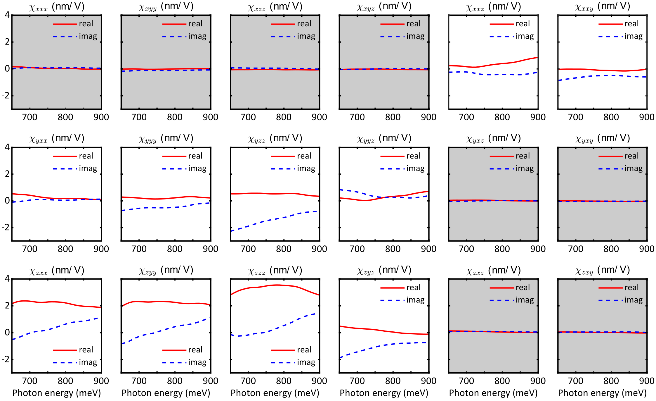
We calculated the nonlinear optical susceptibility for electric-dipole SHG according to the diagrammatic approach to the nonlinear optical response 50, 51. Interband transitions cause two contributions and such that , where
| (5) | |||||
| (6) |
Here, run over directions, , are the band indices, , , represents the transition frequency between bands and , is the difference in band occupation according to the Fermi-Dirac distribution, and is the vacuum permittivity. The derivatives and can be rewritten in terms of the generalized Berry connection 52:
| (7) |
As the summation in Eqs. (5) and (6) only considers interband transitions (), we find . Similarly, we find for the relevant case of . Therefore, all interband contributions to can be related to the generalized Berry connection .
Using and Eq. (4), we can express the SHG intensity as
| (8) |
where we define .