[table]style=plaintop \DeclareNewFloatTypeexamplename=Example \floatsetup[example]style=boxed, objectset=justified, font=footnotesize, capposition=top
A Taxonomy for Requirements Engineering and Software Test Alignment
Abstract
Requirements Engineering and Software Testing are mature areas and have seen a lot of research. Nevertheless, their interactions have been sparsely explored beyond the concept of traceability. To fill this gap we propose a definition of requirements engineering and software test (REST) alignment, a taxonomy that characterizes the methods linking the respective areas, and a process to assess alignment. The taxonomy can support researchers to identify new opportunities for investigation, as well as practitioners to compare alignment methods and evaluate alignment, or lack thereof. We constructed the REST taxonomy by analyzing alignment methods published in literature, iteratively validating the emerging dimensions. The resulting concept of an information dyad characterizes the exchange of information required for any alignment to take place. We demonstrate use of the taxonomy by applying it on five in-depth cases and illustrate angles of analysis on a set of thirteen alignment methods. In addition we developed an assessment framework (REST-bench), applied it in an industrial assessment, and showed that it, with a low effort, can identify opportunities to improve REST alignment. Although we expect that the taxonomy can be further refined, we believe that the information dyad is a valid and useful construct to understand alignment.
category:
D.2.1 Software Engineering Requirements/Specificationscategory:
D.2.4 Software Engineering Software/Program Verificationcategory:
D.2.9 Software Engineering Management—Software quality assurancekeywords:
Alignment, software process assessment, software testing, taxonomyUnterkalmsteiner, M., Feldt, R., and Gorschek, T. 2013. A Taxonomy for Requirements Engineering and Software Test Alignment. {bottomstuff} Author’s addresses: M. Unterkalmsteiner and T. Gorschek, Software Engineering Research Lab, School of Computing, Blekinge Institute of Technology; R. Feldt, Department of Computer Science and Engineering, Chalmers University of Technology.
1 Introduction
Industrial-scale software development is an undertaking that requires judicious planning and coordination of the involved resources. The inception, design, implementation, examination and maintenance of a software product [Scacchi (2001)] are a team effort, organized and executed to satisfy the product customer. Following the separation of concerns principle, software life-cycle models distinguish between different phases or activities in the production of software, linking them by feed-forward and feed-back loops [Madhavji (1991)]. This separation reduces the complexity of each single phase or activity, however at the same time poses needs for an efficient and effective coordination.
In this paper, we investigate two phases in the software development life-cycle, requirements engineering (RE) and software testing (ST), that benefit particularly from a coordinated functioning [Graham (2002)]. Several prominent researchers have called for more research towards this goal. At FoSE 2007, \citeNcheng_research_2007 called for a stronger collaboration between RE and researchers and practitioners from other software engineering fields to improve requirements knowledge and downstream development. \citeNbertolino_software_2007 summarized current challenges and goals in software testing research, pointing out the rising importance of a more holistic approach to ST which takes advantage of the overlaps between different research disciplines. Recent research shows that the study of the synergies between RE and ST are important and of particular interest for industry [Uusitalo et al. (2008), Post et al. (2009), Sabaliauskaite et al. (2010)].
Despite these advancements and its relevance for practitioners, there is still a lack of research that aims at understanding, characterizing and communicating methods that align requirements engineering and software test. By studying methods for RE and ST alignment we intend to fill this gap. This paper does not aim at providing a systematic and exhaustive state-of-the-art survey of RE or ST research, but rather forms the foundation, through a taxonomy, to classify and characterize alignment research and solutions that focus on the boundary between RE and ST. The REST taxonomy also functions as an engine for REST-bench, an alignment assessment framework.
With alignment we mean the adjustment of RE and ST efforts for coordinated functioning and optimized product development. Depending on the context, alignment can be understood as an activity or as a state. Alignment-as-activity pertains to the act of adjusting or arranging efforts involved in RE and ST so that they work better together. To improve our understanding of such activities, we developed the REST taxonomy. Alignment-as-state, on the other hand, refers to the condition of RE and ST efforts having established a coordinated functioning. In order to evaluate the state of alignment we developed REST-bench which acts as an assessment framework and is based on the REST taxonomy. Independently from the context, the above definitions imply that a higher degree of alignment enables higher effectiveness and efficiency in product development and/or maintenance.
In this paper we study RE and ST alignment with the purpose of {longitem}
Characterization of RE and ST alignment methods, providing researchers and practitioners a common vocabulary
Analysis of RE and ST alignment methods, providing researchers means to preemptively identify weaknesses and suggest improvements
Industrial assessment of RE and ST alignment, providing practitioners a lightweight framework (REST-bench, powered by the REST taxonomy) to identify misalignment
The remainder of the paper is structured as follows. In Section 2 we discuss the relationship between requirements engineering and software testing in more detail and illustrate related work. In Section 3 we present the REST taxonomy, accompanied with an example of its application, and classify thirteen alignment methods. In Section 4 we illustrate the process followed for constructing and validating the taxonomy. In Section 5 we analyze the classified methods by the means the REST taxonomy provides. We introduce REST-bench, which we applied in an industrial case study at Ericsson AB, in Section 6. The paper concludes with Section 7, pointing out directions for future work.
2 Background and Related work
2.1 The need for alignment
Software development consists of transitions from system concept, requirements specification, analysis and design, implementation, and test and maintenance [Laplante (2007)]. This abstraction holds for both plan driven process models (e.g. spiral [Boehm (1988)] and evolutionary [Naumann and Jenkins (1982)], and the unified process model [Kruchten (2000)]), as well as and Agile models, although to a lesser extent in the latter category as activities may be blended, eliminating transitions altogether (e.g. in eXtreme Programming [Beck (1999)]).
Looking at the V-Model, which originates from system engineering [Forsberg and Mooz (1991), Bröhl and Dröschel (1995)] and was adopted in software engineering [Pfleeger and Atlee (2009)], high-level testing is often depicted as the Verification & Validation activity to requirements elicitation, analysis and specification. As such, this connection between requirements engineering and testing is a key part of our software engineering knowledge. Still, this connection is not considered in detail as a collective concept in our research activities. On the other hand, an abundance of software technologies, models and frameworks have been developed to ease the transition of software development phases, to bridge the gap between them, and to align the intentions and activities therein, for example, between requirements and software architecture/design ([Kop and Mayr (1998), Amyot and Mussbacher (2001), Hall et al. (2002)]), software architecture/design and implementation ([Murphy et al. (2001), Elrad et al. (2002), Aldrich et al. (2002)]), and software architecture/design and testing ([Muccini et al. (2004), Samuel et al. (2007)]).
However, aligning requirements engineering and software testing is a less explored territory, although it would be beneficial to recognize the inherent link between them [Graham (2002)]. The need for RE and ST alignment is emphasized by the difficulty to design, implement and maintain large software systems. The increase in complexity of the problem space, i.e. requirements, increases also the complexity of the software solution [Glass (2002)], making therefore the testing more involved. Benefits of a strengthened link between RE and ST are, for example, improved product quality [Uusitalo et al. (2008)], cost-effective testing [Miller and Strooper (2010), Flammini et al. (2009)], high quality test-cases [de Santiago Júnior and Vijaykumar (2012)], and early discovery of incomplete requirements [Siegl et al. (2010)].
The means by which RE and ST alignment can be achieved, include (but are not limited to) methods or processes that establish and maintain requirements to test traceability links [Gotel and Finkelstein (1994), Ramesh and Jarke (2001)], use requirements as a driver to develop tests (e.g. by formulating testable contracts [Melnik et al. (2006), Martin and Melnik (2008)], use model-based testing [Utting et al. (2011)]), or organize development teams in an effective manner (e.g. by forming cross-functional teams [Marczak and Damian (2011)]).
The means of achieving alignment are diverse in terms of the assumptions they make, their prerequisites on the organizational environment, and the investments they require. Effectively searching, selecting and applying instruments to improve RE and ST alignment is therefore a challenge for practitioners but also for researchers in advancing the state-of-the-art. \citeNuusitalo_linking_2008 conducted interviews at five Finnish software organizations and elicited practices, such as tester participation in requirements reviews, and requirements to test traceability, that aim to bridge the gap between RE and ST. \citeNpost_linking_2009 explored how the impact of requirements changes, and the subsequent effort in adapting test cases, can be reduced by scenario-based requirements formalizations. In an interview study with software practitioners occupying roles as quality control leaders, requirements process managers and test leaders, Sabaliauskaite et al. identified several obstacles in aligning requirements engineering and testing. Barriers exist in the organizational structure, processes and cooperation between people, and are aggravated by tool deficiencies and challenges in change management [Sabaliauskaite et al. (2010)].
The connections between RE and ST are both clear and numerous, and the potential benefits in increasing the coordination between them are large. Therefore it is essential that we increase our understanding through the study of these connections, and treat them as a collective and not as individual, isolated areas and approaches. Our main aim in this paper is to systematically create a basis for such an understanding. In order to characterize the phenomenon of alignment between RE and ST we developed therefore the REST taxonomy.
2.2 Alignment vs. Traceability
The concept of traceability, which exists since the dawn of the software engineering discipline [Randell (1968)], is not associated with a particular goal, but is a quality attribute of the artifacts produced in software development. The IEEE Standard Glossary of Software Engineering Terminology [IEEE (1990)] defines traceability as “the degree to which a relationship can be established between two or more products of the development process, especially products having a predecessor-successor or master-subordinate relationship to one another […]”. Gotel and Finkelstein provide a similar definition of requirements traceability as “the ability to describe and follow the life of a requirement” [Gotel and Finkelstein (1994)], which complies with the notion of traceability being a work product quality attribute.
Research into traceability indicates that good traceability supports impact analysis [Gotel and Finkelstein (1994), Ramesh and Jarke (2001), Damian et al. (2005), Uusitalo et al. (2008)] and lowers test and maintenance costs [Watkins and Neal (1994), Kukkanen et al. (2009)]. On the other hand, high quality traces are expensive to establish and maintain [Cleland-Huang et al. (2003)], leading to the investigation of means to automate the trace recovery process [de Lucia et al. (2007), Hayes et al. (2007)].
We defined alignment as a goal-directed concept, i.e. the adjustment of RE and ST efforts for coordinated functioning and optimized product development. As such, high quality traces may contribute to an improved alignment, are however not the only solution candidates achieving our goal of alignment. Thus, traceability can be a method to achieve alignment, but the REST taxonomy focuses on the alignment phenomena itself and how methods for alignment (which might build on traceability) can be classified.
2.3 The purpose of taxonomies
Creating taxonomies of objects or concepts has been a basic scientific tool since early work by the Swedish botanist Carl von Linné [Linnaei (1735)]. Taxonomies are means to structure, advance the understanding, and to communicate knowledge [Glass and Vessey (1995), Kwasnik (1999)]. When the understanding in a certain area advances, concepts and relationships between them emerge that allow for a structured representation of these concepts. Being able to communicate that knowledge provides the opportunity to further advance research [Kwasnik (1999)]. Kwasnik also points out the importance of taxonomies as theory developing tools. Classification schemes enable the display of theory in an useful way and serve, similar to theories, as drivers for inquiry [Kwasnik (1992)]. Thus, the development of taxonomies is essential to document theories which accumulate knowledge on Software Engineering phenomena [Sjøberg et al. (2007)].
2.4 Taxonomies in Software Engineering
The Guide to the Software Engineering Body of Knowledge (SWEBOK) is an attempt to characterize the software engineering discipline and to provide a structured access to its body of knowledge [Bourque and Dupuis (2004)]. As such, SWEBOK can be seen as a taxonomy that covers knowledge areas relevant to software engineering, promoting the structured communication of this discipline. Similarly, \citeNglass_research_2002 provide a taxonomy on the research in software engineering, although its main purpose is to structure and to position past research. Blum’s taxonomy of software development methods [Blum (1994)] is more narrow in scope and, similar to Glass et al., aims at structuring rather than communicating the knowledge on software development methods.
Further examples of specialized taxonomies, i.e. with a narrow scope, are \citeNbuckley_towards_2005 on mechanisms of software change, \citeNsvahnberg_taxonomy_2005 on variability realization techniques, and \citeNmehta_towards_2000 on software component connectors.
2.5 Developing Taxonomies
The development of a taxonomy can be approached in two different ways, top-down and bottom-up [Glass et al. (2002)]. In the top-down or enumerative [Broughton (2004)] approach, the classification scheme is defined a-priori, i.e. a specific structure and categories are established that aim to fulfill the purpose of the taxonomy. The created classification scheme is thereby often a composition of previously established schemata (e.g. [Glass et al. (2002), Avižienis et al. (2004), Bunse et al. (2006)]), or the result of the conceptual analysis of a certain area of interest (e.g. [Svahnberg et al. (2005), Utting et al. (2011)]). The strength of this approach is that the taxonomy is built upon existing knowledge structures, allowing the reuse of established definitions and categorizations and hence increasing the probability of achieving an objective classification procedure.
On the other hand, the bottom-up or analytico-synthetic [Broughton (2004)] approach is driven by the sampling of subjects from the population of interest and the extraction of patterns that are refined into a classification scheme. For example, \citeNvegas_maturing_2009 extended existing unit-testing classifications by systematically studying the Software Engineering literature, supplemented by gathering the expert judgment of researchers and practitioners in the testing area. The strength of this approach is that new, not yet classified, characteristics may emerge and enrich existing taxonomies.
The goal of the taxonomy presented in this paper is to classify methods that bridge the gap between requirements engineering and software testing activities. There exists a rich knowledge base for both RE and ST, and taxonomies for classifying aspects in each area already exist. Following a top-down approach and amalgamating concepts, definitions and categorizations from these separate areas into a taxonomy of RE and ST alignment seemed to us unlikely to succeed. Even though the respective areas are mature and have seen a lot of research, their interplay and connections have been less explored. Hence we chose to construct the taxonomy in a bottom-up fashion, validating the emerging classification scheme throughout the process (see Section 4).
3 The REST Taxonomy

When developing a taxonomy one has to consider its purpose [Glass and Vessey (1995)]. A specific taxonomy is designed to accommodate a single, well-defined purpose. On the other hand, the structure of general taxonomy is not imposed by a specific purpose [Glass and Vessey (1995)] and is hence applicable in various circumstances. As we defined earlier in Section 1, alignment can be understood as an activity or a state. We therefore designed the structure of our taxonomy to accommodate both aspects of the alignment definition. From the alignment-as-activity perspective, the REST taxonomy can be used to analyze and categorize alignment methods described in literature. From the alignment-as-state perspective, the REST taxonomy serves as an analysis aid in project and process assessment. The method we developed for process assessment (which connects to alignment-as-state), REST-bench, is described and illustrated through a case study in Section 6.
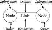
Figure 1 provides an overview of the REST taxonomy. The taxonomy is centered around our observation (see Section 4.1) that the alignment of RE and ST implies some sort of information linkage or transfer between two entities involved in either process area. In essence, if there is no exchange of information, at least at some point in time, no alignment can take place or be achieved. Thus, characterizing such exchanges are key in a general taxonomy. In order to describe this phenomenon we devised the concept of an information dyad, representing the central unit of analysis in the taxonomy. The information dyad contains the criteria for differentiation and description [Glass and Vessey (1995)] used for the classification, the second essential aspect in taxonomy development. Figure 1a illustrates the components of an information dyad. A node is characterized by the type of information it represents and an owner of that information. Two nodes are connected by a link, characterized by the type of mechanism establishing the link between nodes, and the medium through which the link is realized.
The third important property of a taxonomy, besides its purpose and criteria for differentiation, is the method of classification [Glass and Vessey (1995)]. The method should illustrate and explain how objects under study are classified in a repeatable and unambiguous manner. To this end we developed a process, summarized in Table 3, in which each step answers a specific question.
The objects under study are methods that may improve the alignment between RE and ST, published at conferences or in journals. Hence, Step 1 in the process serves as a gatekeeper, asserting that the taxonomy is applied on studies that can answer the questions asked in the following steps. Steps 2.1, 2.2 and 2.3 aim at identifying the information dyads of the studied method, and characterizing the dyads by their components (information, medium and mechanism). The context in which the alignment method has been developed or applied is captured in Step 3.
Since an alignment method consists of one or more dyads, these dyads form a structure which characterizes the method (Figure 1b). In Step 4 we analyze the properties of the dyad structure which allows us in Step 5 to classify the methods according to their complexity and scope/focus (Figure 1c).
The remainder of this section describes the process shown in Table 3. To complement the description, we illustrate the application of the taxonomy by self-contained examples, based on \citeNmiller_case_2010 case study on their framework and method of model-based testing of specifications and implementations. Note that section and figure numbers in the examples refer to \citeNmiller_case_2010. Finally, we apply the taxonomy on 13 alignment methods in Section 3.5.
REST classification process Step Question answered Section 1 Does the study shed light on both RE and ST aspects? 3.1 Relevance 2 What are the components of the information dyad? 3.2 The information dyad 2.1 What type of information exists/is used in RE and ST? 3.2.1 Information 2.2 What type of medium connects the information? 3.2.2 Medium 2.3 What type of mechanism establishes the connection? 3.2.3 Mechanism 3 In which environment is the method situated? 3.3 Method context 4 What is the structure of the identified dyads? 3.4 Dyad structure properties 5 How can the method be classified? 3.5 Method classification
3.1 Relevance
The analyst (the person who applies the taxonomy) needs to decide whether the study, and the described alignment method therein, qualifies to be classified with the taxonomy. He bases his decision on three independent criteria: {longitem}
Scope: Since the taxonomy aims at characterizing links between requirements engineering and software testing activities, the candidate study should consider both areas in the discussion of the presented method. If, for example, the focus of the study is on formal reviews of requirement specifications, considers however also the effects of reviews on downstream development including testing or discusses the involvement of quality assurance personnel in reviews, the study is likely to be adequate for taxonomy application. On the other hand, a comparison of different review techniques, focused on identifying respective strengths and weaknesses alone, is likely not to be adequate.
Comprehensiveness: A detailed report of the conducted study reduces the analyst’s leeway for interpretation when answering the questions posed in Table 3. It is impossible to judge the comprehensiveness of a publication a-priori, i.e. before reading it, but since space restrictions of journals are less rigid than for conference or workshop publications, they tend to exhibit more details on the conducted study.
Rigor: In case the publication includes a method evaluation, rigor of reporting context, design and validity threats [Ivarsson and Gorschek (2010)] should be considered. A strong description of these aspects supports the analyst in performing context identification (Step 3, Section 3.3).
The example for Step 1 shortly introduces the publication on which all following examples in this section are based upon, and illustrates the application of the above discussed criteria to assess relevance.
Example 3.1 (t).
Step 1 - Does the study shed light on both RE and ST aspects? \citeNmiller_case_2010 present and evaluate a framework that aims at taking advantage of synergy effects between specification testing and implementation testing. They argue that the effort spent in verifying the formal specification of a software system can also contribute to the verification of the implementation of that system. To this end, they introduce testgraphs as a mean to model parts of the specification that require testing, using them for the derivation of test sequences in both specification and implementation testing.
The table below illustrates our assessment with respect to the relevance criteria we defined.
| Criterion | Strength | Weakness |
|---|---|---|
| Scope | + includes both RE and ST activities (Section 3) | - derivation of formal specifications from requirements is not part of the framework (Figure 2) |
| + consistency and conformance check between testgraph and formal specifications (Section 3.1) | ||
| Comprehensiveness | + activities respectively roles are described (Section 3, Section 5) | |
| Rigor | + context (Sections 4.2-4.4) and design (Section 4.1, Section 7) described | - threats to the validity of the evaluation not discussed |
| + risks in the application of the framework are considered (Section 3.3) |
Based on this assessment, we conclude that we can apply the REST taxonomy on the described method.
3.2 The information dyad
The goal of this step is to identify the nodes and the link that characterize an information dyad (see Figure 1a). Note however that an alignment method can be described by more than one dyad, depending on the number of identified nodes. Hence we discuss dyad structures and their properties in Section 3.4.
3.2.1 Information
An information dyad consists of two nodes and a connecting link. A node describes an entity that has to be aligned, synchronized, brought into agreement, with another entity. The nodes represent the different, primary objects of information, while the link represents the fact that they are or should affect one or both of each other. To differentiate between nodes, we assign each node a name, characterizing its purpose. We deliberately do not limit the definition of a node to the notion of, for example, a phase in the software development life-cycle. A node could also be an activity, e.g. formal inspections during requirements analysis. Although this allows for more flexibility, it also reduces the repeatability in the classification of the alignment method.
A node is characterized by the information it contains and an owner who is the source of that information. In this work, we informally define information as a coherent collection of related data that is created during software development, often with a specific purpose in mind. Later on in Section 3.2.3 we will further refine the notion of the information concept, but for this step in the classification process this operational definition is sufficient.
Information, according to the above definition, is created, recorded and used at any point in time during software development, enabling product inception, specification, implementation, verification and validation, and maintenance. Typically it refers to development artifacts but it can also represent more intangible but essential and purposely related knowledge of a developers or testers [Feldt (2002)], e.g. informal requirements as in the Miller and and Strooper case (see the example for Step 2.1). With this taxonomy we aim to capture in particular information that is shared and aligned in RE and ST activities. This does however not restrict the information content to RE or ST topics, e.g. technical requirements, feature descriptions, priorities, test plans, strategies, scenarios, etc. Information valuable for alignment can emerge from any phase in software development and connect RE and ST activities. Hence, the task of the analyst is to carefully study the described method and collect evidence for the existence of a node and its characterizing information. Such evidence can be found in statements on used or created artifacts or in descriptions of things that have been discussed or communicated. The owner, the second attribute of a node, is responsible for creating and/or maintaining the information. Depending on the organization of the development process, the owner may be formally assigned to this responsibility (i.e. by occupying a specific role or function) or, in case of agile processes, depend on the employee’s current activities.
Example 3.2 (t).
Step 2.1 - What type of information exists/is used in RE and ST? To answer this question, we focus first on identifying actors and the information on which is acted upon. The framework description and the illustration of the performed tasks in the GSM case study are thereby of interest (Section 3, 3.1, 3.2, 5.1, 6.1 and 6.2). Remember that our ultimate goal in this step is to identify potential nodes that form one or more information dyads. Hence the other components, medium and mechanism, play a secondary role at this moment. Defining the characteristics of links too early in the process may inhibit the discovery of all relevant nodes. On the other hand, since Steps 2.1-2.3 are performed iteratively, refinements are still possible at a later moment. The table below lists the identified nodes. In the following we will motivate them and illustrate in which relation they stand to each other, i.e. define the information dyads in this example.
| ID | Node name | Information | Owner |
|---|---|---|---|
| N1 | Requirements specification | Informal requirements | Req. engineer |
| N2 | Req. analysis (Implementation) | Formal specification | Req. engineer |
| N3 | Req. analysis (Test) | Testgraphs | Tester |
| N4 | Specification test | Test sequence | Tester |
| N5 | Specification mapping | Spec. to impl. mapping | Tester |
| N6 | Testgraph mapping | Testgraph to impl. mapping | Tester |
| N7 | Implementation test | Test sequence | Tester |
| Dyads (6): N1-N2, N1-N3, N3-N4, N2-N5, N3-N6, N6-N7 | |||
The first node, N1, contains the fundamental information, i.e. informal requirements, from which further artifacts are derived. The formal specification is developed by the requirements engineer to aid design and implementation. Hence we define requirements analysis (Implementation) as the second node (N2). Similarly, the tester develops a testgraph, with associated test cases, to aid the verification of the formal specification and the implementation. Requirements analysis (Test) is therefore the third node (N3). The dyads, N1-N2 and N1-N3, follow from the refinement performed by requirements engineers and testers. The specification is tested by generating test sequences (N4) from the testgraph, leading to dyad N3-N4.
Identifying the next nodes is rather challenging. Figure 2 identifies the test oracle and the implementation as further artifacts relevant for the framework. From the alignment perspective however, the interesting part of the framework is the mapping between specification respectively testgraph to the implementation, described in Sections 6.1 and 6.2. The reason why it is interesting is that the tester needs to process and understand artifacts developed by requirements engineers (formal specification) and developers (implementation). Hence, specification mapping (N5) and testgraph mapping (N6) are nodes of interest, leading to dyads N2-N5 and N3-N6 representing the relationships of the mapping. The implementation test (N7), also based on the derivation of a test sequence, is driven by the testgraph mapping, leading to dyad N6-N7.
3.2.2 Medium
The Oxford English Dictionary defines the term medium as “an intermediate agency, instrument, or channel; a means; especially a means or channel of communication or expression” [Oxford English Dictionary (2011)]. The medium in an information dyad describes how the information between two nodes is linked together. This can be through a carrier of information, e.g. an artifact, or a facilitator that enables the information transfer, e.g. a process. During the development of the taxonomy we have identified a set of different media types:
-
•
Structured artifacts (e.g. documents, email, diagrams, database records); they are usually persistent and searchable/indexed.
-
•
Unstructured artifacts (audio, video); they are usually not searchable/indexed.
-
•
Tools that act as means to share, transfer or transform information (e.g. modeling tools, language analysis tools).
-
•
Process (one or more activities, can be performed repeatedly).
-
•
Organization of work environment (co-location, role/responsibility rotation).
The analyst can choose one of these media types if appropriate or introduce a new type as the above set was derived only from a sample of alignment methods studied and hence be incomplete.
Example 3.3 (t).
Step 2.2 - What type of medium connects the information? For each dyad identified in Step 2.1 we now define their linking medium.
In the dyad Requirements specification - Requirements analysis (Implementation), a requirements engineer is responsible for deriving the formal specification from informal requirements. We have to assume that this derivation is performed manually, following a certain process, since the framework description does not explain this step in detail. Hence, for the dyad N1-N2 we declare the medium to be a process.
Similarly, testgraphs are derived by a tester from the informal requirements, represented by the dyad Requirements specification - Requirements analysis (Test). Also here, the derivation is a series of activities (define testgraph and associated test cases, measure specification coverage) that follows standard testing heuristics. Hence we declare also in the dyad N1-N3 the medium to be a process. The generation of test sequences (N4) is supported by a tool for the editing the graph and executing tests, leading to the conclusion that the medium in dyad N3-N4 is a tool.
Both in dyad N2-N5 and N3-N6, in which mappings between a model (specification respectively testgraphs) and the implementation are created, the link medium is a process. The tester implements wrapper classes for the classes under test (dyad N2-N5), linking state, operations, input and output, and return values from the implementation to the corresponding entities in the specification. In dyad N3-N6, the tester performs a similar task by implementing a driver class that calls for each traversed node and arc in the testgraph the appropriate operation in the wrapper class. Although both mappings can be potentially created automatically, such a tool is currently not available in the framework. On the other hand, the generation of test sequences for the implementation test (N7), is tool supported. Hence the medium in dyad N6-N7 is a tool.
3.2.3 Mechanism
The mechanism component of a dyad link characterizes the way in which information is carried, eventually changing its purpose, from one node to the next. We assume that a node in a dyad fulfills a certain purpose in the development of software and is hence embedded in a context that supports the realization of that purpose. For example, requirements analysis is performed at a certain point in time by people possessing the knowledge to select, prioritize and validate requirements. Test scenarios may be developed at the same time, but require a different set of knowledge in order to realize their purpose. When information is aligned between two nodes, the context of the nodes differs and hence also the purpose of the information.
In Section 3.2.2 we have motivated how a link between two nodes can be characterized by a medium. The concept of a medium is however not able to explain how the information between two nodes is synchronized, i.e. how the change in purpose is supported by the link. Therefore we use the concept of mechanism to further characterize the link in information dyads.
To understand the mechanism concept we need to refine our earlier definition of information as a coherent collection of related data that is created during software development, often with a specific purpose in mind. Although this definition helps to identify nodes, as discussed in Section 3.2.1, it does not provide the granularity to differentiate between alignment mechanisms. We adopt therefore a definition in which information has the components of well-formed data and meaning [Floridi (2010)]:
-
1.
data is well-formed if it has an underlying structure, syntax and notation
-
2.
data is meaningful in a certain context, i.e. the meaning of data may change with its purpose
Example 3.4 (t).
Step 2.3 - What type of mechanism establishes the connection? We start by looking at the dyads that contain both N1, informal requirements, as an information characteristic in the node. The information in both N2 and N3 is derived, although by different roles, from the informal requirements. The mechanism for this derivation is in both cases not explicitly specified in the framework. Hence the connection between the nodes is in both dyads an implicit one. The mechanism in dyad N3-N4 is however a transformation as test sequences are extracted from the testgraph which are used to animate and test the specification.
Dyads N2-N5 and N3-N6, on the other hand, are explicitly connected by the tester, creating a mapping between the implementation and the specification respectively the testgraph. The mere mapping between information in these dyads does not fulfill the requirements of a transformation mechanism. Consider for example that the testgraph in N3 is modified due to changes in the informal requirements. The mapping by itself cannot accommodate such impact but has to be recreated by the tester. The mapping identifies corresponding entities in the artifacts, i.e. there is no change in the notation, excluding therefore also bridge, leading to the conclusion that we observe a connection mechanism. Dyad N6-N7 is linked again by a transformation mechanism since the test sequences are generated and reflect the information in the testgraph mapping (N6).
Using these components of information, we can now differentiate between alignment mechanisms and characterize them according to the means through which the synchronization and agreement of information, shared between nodes, is achieved.
Transformation: Information, packaged for one node in the alignment dyad, is re-packaged in order to satisfy the needs of the other node. A transformation mechanism that restructures and/or augments the information is applied, changing the notation and supporting the change in meaning of the data. Example: A method allows the transformation of a use case into a test model, changing the notation of the information. The support in adapting the meaning is given, for example, if relationships to other use cases are pertained in the transformation and reflected in the model111Support in adapting the meaning = preservation of relationships between information across contexts. We say that the alignment between nodes is internalized in the mechanism.
Bridge: Information pertaining to each node is connected and augmented in order to achieve fitness of purpose in both nodes, changing the notation. The difference to transformation is that a bridge does not provide support to adapt the meaning of data within the context change. Example: A method allows the transformation of use cases into a test model, changing the notation of information, however without establishing relationships within the test model that reflect the relationships within the use cases. Adding a new use case to the test model is supported syntactically, but the positioning in the test model requires some knowledge which is not provided by the method. We say that the alignment between nodes is semi-internalized in the mechanism.
Connection: Information pertaining in each node is connected, establishing a logical link between the two nodes. The mechanism does however not change the notation, nor does it provide support in adapting the meaning of the data when changing the context. The difference to the above is that the connection does not add anything to the information’s fitness of purpose, except establishing a correspondence of the data component of information. Example: A method allows to link use cases to the corresponding parts of a test model, without however providing syntactical support. The meaning of the information within the test model is given only by the connections back to the use cases. We say that the alignment between nodes is not internalized in the method.
Implicit connection: Information is connected by volatile and implicit links that are not formalized. Such volatile links can be established by communication between people or they exist within a shared, commonly agreed upon, model. As such, it is not evident which of the components of information are effectively manipulated in a context change.
Note that the alignment mechanisms stated above are characterized by their support in preserving the relationships between information across contexts and not by their degree of automation. None of the alignment mechanisms implies that the mechanism is or can be automated.
3.3 Method context
In the previous step we focused on characterizing information dyads in a rather detailed manner by describing their components. In this step we broaden our view and study the context in which the described method is embedded. \citeNpetersen_context_2009 argue that context influences the conclusions drawn when integrating evidence from industrial studies. In a classification effort it is hence important to capture the context of the classified objects. In the following paragraphs we illustrate the context aspects that should be captured.
Example 3.5 (t).
Step 3 - In which environment is the method situated? The table below summarizes the context of the classified method [Miller and Strooper (2010)].
| Aspect | Description |
|---|---|
| Method setting | implementation of a subset of the GSM specification (<1 KLOC), focus on functional requirements, model-based testing, bespoke requirements, natural language requirements and GSM standard specifications |
| Focus | 2) Unintentional but noted effect on alignment1 |
| Motivation | None given due to unintentional focus |
| Assumptions | The specification (language) is executable |
| Quality targets | Not stated |
| Validation | Testgraphs are reviewed for correctness and completeness, testgraph coverage of specification is measured |
| Outcome | Cost-effectiveness comparable to other model-based techniques, better than manual testing |
-
1
Focus is unintentional since their goal was to improve efficiency by reusing the testgraph in specification and implementation testing. The testgraph concept is interesting from the alignment perspective, since it is independently derived and hence an alternative representation to formal specifications of the informal requirements.
Method setting: Describe type of development process, scale / size (of the project in which the method was applied), focus of requirements types (functional, quality, both), type of testing (unit, integration, system, acceptance, formal verification, scenario-based, etc.), and type of requirements engineering (market-driven or bespoke, use of natural language primarily or other notation).
Focus: Describe the degree to which alignment of RE and ST is the primary focus of the method. Is an alignment issue between RE and ST thematized and addressed (choose 3, 4, or 5)? Are the studied methods/activities embedded in a software engineering problem that includes, but does not exclusively discuss RE and ST alignment (choose 1, 2, or 3)?
-
1.
Unintentional and undiscussed / unnoted effect on alignment
-
2.
Unintentional but noted effect on alignment
-
3.
Part of purpose was to improve / affect alignment
-
4.
Main purpose was to improve / affect alignment
-
5.
Intended, main as well as sole purpose
Motivating problem: Describe the driver / intention / motivation to propose / implement an alignment method.
Assumptions: Describe any constraints or assumptions, e.g. on existing artifacts or application domains, that the application of the alignment method makes.
Quality targets: What is aimed to be improved by a better RE and ST alignment? Examples are reducing time-to-market, test effort, cost, number of faults, etc.
Validation: Is there any formal or informal mechanism that supports the consistency of the shared information? In particular, does the alignment method provide any support in assessing / verifying the consistency or correctness of the shared information?
Outcome / Benefits: What are the experienced effects of the alignment method? Note that this should only contain actual (not expected ones) effects that were established by an evaluation.
3.4 Dyad structure properties
The central unit of analysis of the REST taxonomy is the information dyad (Figure 1a). As we have illustrated in the examples in Section 3.2, a REST alignment method may consist of several dyads, thus forming a structure that is governed by the components of a dyad (Figure 1b). We have defined a set of six properties based upon the characteristics of nodes and links, explained in Sections 3.4.1 - 3.4.6 and illustrated in the example for Step 4. The most basic property is the number of nodes in a dyad structure. Other properties are derived from the purpose of a node, i.e. in which development phase it predominately exists, or the alignment mechanism of the link between two nodes. The definition of these properties is guided by their usefulness in interpreting and analyzing a dyad structure. In Section 3.5 we propose a classification of alignment methods based upon dyad structure properties.
3.4.1 Number of nodes (P1)
Links between nodes need to be established and maintained over time. Hence, the total number of nodes allows one to reason on the (visible, explained) complexity, and on the effort to establish and maintain REST alignment. A large number of nodes may indicate a high cost in institutionalizing alignment. Furthermore, even tough a larger number of nodes can break down the alignment process into manageable sub-tasks, the overall complexity of the method increases with the number of nodes, as linking mechanisms between the nodes need to be defined and instantiated.
3.4.2 Branches (P2)
Looking at an individual dyad, one node acts as a source, the other as a sink of information. A branch exists, if the dyad structure is configured such that a node acts as a source or sink for more than one node. We provide in the example for Step 4 a procedure to identify branches in a dyad structure.
Branches may reduce the complexity of analyzing information (concern separation) in sink nodes. However, at the same time branching requires a step in which the individually analyzed information is merged, introducing more nodes, potentially more effort and an increase of the overall methods’ complexity.
Example 3.6 (t).
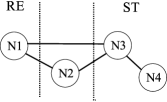
Step 4 - What is the structure of the identified dyads? The figure below illustrates the dyads that were identified in the method presented by \citeNmiller_case_2010, using the data gathered in the examples for Step 2.1, 2.2, and 2.3.
![[Uncaptioned image]](/html/2307.12477/assets/x4.png)
In this example we show how the dyad structure properties are derived from this data.
P1: This property is calculated by counting the number of nodes identified in the method, which is in this case 7.
P2: The dyads are N1-N2, N1-N3, N3-N4, N2-N5, N3-N6, N6-N7, whereby the first node represents the source, and the second node the sink of information. From this sequence, we can identify the number of branches by counting the dyad instances where a source or sink node occurs more than once. In this example, this is the case for 2 source nodes (N1, N3), leading to the conclusion that we observe 2 branches in this method.
P3: Nodes N5 and N6 are intermediate nodes, hence the value for this property is 2.
P4: The RE and ST node proportion is 2 (N1,N2) : 3 (N3, N4, N7).
P5a/b/c: This property is extracted by listing the link mechanisms in the respective phases. The only Within-RE link is an implicit connection, and the Between-Phase links are implicit connection, two connections, and a transformation. The only Within-ST link is a transformation.
P6: For this property, we look at the nodes that act exclusively as source and sink of information in RE and ST respectively. In RE, N1 is the only node that acts exclusively as source (N2 is both sink and source). The information in N1 is informal requirements, which can be regarded as information pertaining to early RE. In ST we have N4 and N7 that act both exclusively as sinks. Both contain test sequences (for specification and implementation tests respectively), which can be seen as information pertaining to late ST. Hence the scope for this method is Early RE - Late ST.
3.4.3 Intermediate nodes (P3)
Nodes characterized by information that belongs to the design/analysis or implementation phase of software development are intermediate nodes. Their existence indicates that the method user is required to have knowledge outside the RE and ST domain. Intermediate nodes may strengthen overall REST alignment by integrating analysis/design and implementation, increasing the traceability. However, intermediate nodes can also imply that the method may be more invasive to the overall development process.
3.4.4 RE and ST node proportion (P4)
Assuming that a node is associated with a certain cost (e.g. establishing/maintaining the information therein and links in between), it is of interest to know the node distribution among the RE and ST phases. Such an evaluation may show which phase is impacted the most by a method. Having more within-phase nodes (and links) in RE may be beneficial as the level of abstraction can be adjusted to a level that facilitates the alignment with ST. On the other hand, nodes (and links) in RE need to be efficient as requirements may change and may be refined continuously, promoting less nodes in the RE phase.
3.4.5 Within-RE (P5a) / Between-Phase (P5b) / Within-ST links (P5c)
Based upon the information characterizing a node, we can approximate roughly its primary development phase and whether it is located early or late in that phase. This allows us to reason upon the linking mechanisms within the RE and ST phases, and between those phases. The reason for such a distinction emerges from the assumption that each phase has different properties that need to be taken into account by the applied linking mechanism(s). For example, Within-RE links may need to accommodate frequent requirement changes, informally specified requirements and different requirement abstraction levels [Gorschek and Wohlin (2006)]. Within-ST links typically link test cases on different abstraction levels, whereas Between-Phase links require a more complex mapping since the context in the phases differs.
3.4.6 Scope (P6)
By approximating the location of nodes in development phases, we can distinguish between early and late nodes. The distinction between early and late requirements is often made to differentiate between an “understanding” and “describing” phase in RE (e.g. in the Tropos development methodology [Mylopoulos and Castro (2000)]). Similarly, one can also distinguish between early and late phases in ST. For example in RE, early artifacts can be natural language requirements and use case descriptions, whereas requirements models can be put closer to the Analysis/Design phase. Similarly, test scenarios, abstract test cases and test plans can put on the left, executable test cases on the right spectrum in ST. This allows us to reason upon the scope of an alignment method with respect to the RE and ST phases, and its implications. For example, a method may not provide a link between natural language requirements and more formalized models. In a scenario where such a link would be beneficial, the method may need to be extended or combined with other approaches.
3.5 Method classification
Up until now we have illustrated the REST taxonomy from the viewpoint of a single alignment method, that is, describing the process of identifying information dyads, extracting the context in which the method is applied/used, and characterizing the method through dyad structure properties. In this section we expand this view by proposing a classification schema for alignment methods, based upon dyad structure properties.
3.5.1 Overview of the classified methods
We have applied the taxonomy, in total, on 13 alignment methods. In the remainder of this paper they are referenced as cases A-M: A [Güldali et al. (2011)], B [Flammini et al. (2009)], C [de Santiago Júnior and Vijaykumar (2012)], D [El-Attar and Miller (2010)], E [Miller and Strooper (2010)], F [Nebut et al. (2006)], G [Conrad et al. (2005)], H [Abbors et al. (2009)], I [Damian et al. (2005)], J [Arnold et al. (2010)], K [Zou and Pavlovski (2008)], L [Siegl et al. (2010)], and M [Metsa et al. (2007)].
Cases F-M stem from the set of papers that were used for taxonomy construction, whereas cases A-E stem from a search in literature, as explained in Section 4.1. Since the identification and characterization of information dyads is a crucial step in the application of the taxonomy, we provide additional examples of this process on cases A-D in Appendix A.1 (case E has served as a running example throughout this section).
3.5.2 Classification schema
The schema we adopt aims at providing a meaningful and useful classification of alignment methods. Looking at the definitions of the dyad structure properties in Section 3.4, we can observe that properties P1, P2, P3 and P5 characterize the complexity, and P4 and P6 describe the focus and scope of the method. We chose therefore a simple two-dimensional schema that encodes the overall complexity of the classified method on the vertical and the focus/scope on the horizontal axis. Since we use multiple properties to represent complexity, we define the following order for sorting a method on the complexity dimension:
-
1.
P1 (Number of nodes): this is the main sorting criterion as each node, through its associated information, contributes to the need of maintaining consistency (otherwise, the very purpose of the method would be violated).
-
2.
P5b (Between-Phase links): each link that crosses a phase boundary (e.g. from RE to design, RE to ST), contributes to the overall complexity as information from different contexts is linked. We use the number of Between-Phase links as the second sorting criterion.
-
3.
P5ac (Within-RE and Within-ST links): linking information on different abstraction levels is less involved than linking information from different contexts; as these links lie within one phase, we use the number of Between-Phase links as third sorting criterion.
-
4.
P2 (Branches): even though related to the number of links, branches are less indicative for the overall method complexity as they act locally (i.e. within a dyad) as an agent to reduce complexity. They are therefore the fourth sorting criterion.
-
5.
P3 (Intermediate nodes): everything else being equal, intermediate nodes are the fifth sorting criterion.

Note that the ordering above considers only complexity defined by the properties we have identified. For example, we do not classify the information in a node itself. Hence, the complexity of an alignment method, as defined by the classification schema, is an approximation that can be improved by a more fine-grained characterization of a node’s information component. As a consequence, the presented classification does not provide any statement on the performance of the classified alignment methods. Nevertheless, the qualitative classification of the method context (see Section 3.3 and Table A.1), in particular the method setting, assumptions and quality target aspects, provide means to interpret and judge the quantitative classification.
The second dimension of the schema (horizontal axis), characterizes the methods according to their focus (P4) and scope (P6).
3.5.3 Classification results
Figure 2 shows the 13 classified cases. In the left-most column, we encode the dyad structure details in a signature, whereas in the right part of the figure, the structure is represented graphically (only Between-Phase links are drawn). Note that cases A, K, M and I have the same complexity according to the sorting criteria defined in Section 3.5.2. We analyze the results of the classification in Section 5.
4 Taxonomy construction and validation method
In this section we describe how we constructed and validated the taxonomy, and discuss threats to validity of this approach.
4.1 Iterative construction and validation
In Section 2.5 we motivated why the taxonomy was constructed in a bottom-up fashion. We started by sampling alignment methods published in literature. The initial sample consisted of 16 publications that were analyzed in a systematic mapping study on aligning requirements specification and testing [Barmi et al. (2011)]. Since the mapping study had limitations, as further discussed in Section 4.2.1, we added 10 more publications that we regarded relevant by reading title and abstract. Hence, the taxonomy construction pool consisted of 26 publications, from which 15 were used in the taxonomy construction process (iteration 1-4). Although we used all 15 publications in the construction process, we classified 8 of them (cases F-M) and excluded 7 for the following reasons:
-
•
the publication covered only the RE aspect, leading to the decision that the method, described in this particular study, is out of scope: 4 publications ([Hayes et al. (2006), Grunske (2008), Mugridge (2008), Niu et al. (2009)])
-
•
the publication only sketched a solution proposal or reported lessons learned, and was therefore not descriptive enough to warrant a classification: 2 publications ([Winbladh et al. (2006), Kukkanen et al. (2009)])
-
•
the publication is a predecessor to a publication that has been classified in this paper: 1 publication ([Nebut et al. (2004)])
In iteration 5 we classified 5 more publications (cases A-E) that were not included in our initial pool, resulting in a total of 13 classified methods that are presented in this paper.
Three researchers were involved at different stages in the construction and validation of the taxonomy. The milestones of this iterative process are illustrated in Figure 3. We discuss these iterations in the following subsections.
4.1.1 Iteration 1
In the first iteration we chose five publications to bootstrap a set of dimensions for the classification of alignment methods. The first author applied open coding [Robson (2002)] on each method description and consolidated the emerged codes into dimensions characterizing the alignment approaches (v0.1 of the taxonomy, see Figure 3).
The strategy was to identify commonalities or distinguishing aspects in the described methods. For example, one common aspect was that information from the requirements engineering phase is reused in downstream development and eventually in system or acceptance testing, leading to a dimension describing information source and sink. Another early dimension, describing the packaging of information (e.g. in natural language, diagrams, etc.), characterized whether information is used “as is” or if it is adapted or enriched for downstream use.

4.1.2 Iteration 2
In the second iteration, the second author was invited to verify whether the identified dimensions characterize the methods in an useful manner. We re-used the publications from iteration 1. Although the definitions of the dimensions were refined in this iteration, we realized that a characterization of the heterogeneous set of methods would not be possible with static dimensions describing the method as a whole. For example, methods could be characterized by several information sources and sinks. Hence we introduced the concept of information dyads which allowed us a more fine-grained and flexible characterization, leading to v0.3 of the taxonomy.
4.1.3 Iteration 3
The first and second author chose five new publications for the third iteration. The dimensions, now consolidated in the information dyad construct and the context aspects, were further refined and a guideline was developed (v0.5 in Figure 3). We chose two additional publications and exemplified the application of the taxonomy in the guidelines.
4.1.4 Iteration 4
We invited the third author to validate the updated taxonomy and the operational guidelines developed in the previous iteration. We chose three new methods from the sample set and all three authors independently applied the taxonomy. We analyzed the results in a post-mortem.
On method 1, we achieved in general a good agreement, having however some variance on the identified medium (link characteristic) and the level of focus on alignment (context aspect). Looking at the guidelines, we identified the definitions of the different media and alignment focus levels as a cause for the disagreement and clarified them. On method 2 and 3 we observed a larger variance among the three analysts. The major reason was a disagreement on whether the method is in the scope of the taxonomy, i.e. if it can be classified as an alignment method. Hence we added Step 1, identifying the relevance of the studied method, in the taxonomy application process (see Table 3). The intention of the scope criterion is to clarify that we are interested in classifying methods that consider both requirements engineering and testing aspects. Methods that bridge other gaps, e.g. between design and test, are by this definition excluded.
4.1.5 Iteration 5
The aim of this iteration was to apply the taxonomy on a set of methods that were not included in the initial set of publications. To this end, we chose four premium venues for publications in Requirements Engineering (Requirements Engineering Journal), Verification & Validation (Software Testing, Verification and Reliability) and software engineering in general (IEEE Transactions on Software Engineering, Software Quality Journal) as the population for drawing our sample. We chose 2007 as the starting point for our search since we did not aim to perform a systematic literature review [Kitchenham and Charters (2007)] and hence do not claim complete time coverage. Furthermore, 2007 seemed to be a good starting point since \citeNcheng_research_2007 and \citeNbertolino_software_2007 called for a closer collaboration between requirements engineering and software testing research at FoSE that year.
The first author manually searched, by reading title and abstract, 635 publications from the period 2007 - 2011, applying the criteria defined in Section 3.1. After applying the scope criterion on the abstracts, 148 publications remained for full text screening. In this step, the scope criterion was applied a second time, excluding methods that were only partially bridging the gap between RE and ST, e.g. verification of UML models [Siveroni et al. (2010)], derivation of specifications from requirements [Seater et al. (2007)], or derivation of test cases from design artifacts [Pickin et al. (2007)], leading to 24 publications222In the title and abstract screening we were rather inclusive, resulting in many irrelevant studies in the set for full text reading.. On these, we applied the comprehensiveness criterion, including only those methods for which we could answer the questions posed in steps 2 and 3 of the taxonomy application process (see Table 3). We concluded the search with 5 publications describing alignment methods and applied the taxonomy, leading to two further refinements to the guidelines: {longitem}
Introduction of use-relationships between nodes. For example in Case B (see Table 1b), node N3 contains information that is necessary for the method, is however not related with any other node through a link mechanism. The use-relationship legitimates N3 in the dyad structure, increasing the richness of the method characterization.
Introduction of a further aspect in context identification (Step 3) of the taxonomy process (Section 3.3). Recording assumptions or constrains helps to understand under which circumstances a method may be applicable. The results of the taxonomy application on four cases (one method has served as the running example in Section 3) are illustrated in Appendix A.1.
4.1.6 Iteration 6
The aim of this iteration was to evaluate whether the REST taxonomy provides support in identifying misalignment in a development organization. The first author developed an assessment guideline and procedure, REST-bench, that is powered by the concepts underlying the REST taxonomy. The approach and assessment results are described in Section 6.
4.2 Validity threats
The bottom-up construction of the taxonomy is subject to several validity threats [Wohlin et al. (2000)].
4.2.1 Internal validity
The systematic mapping study by \citeNbarmi_alignment_2011, from which we sampled publications and bootstrapped the dimensions of the taxonomy, was initially designed to identify alignment methods focusing on non-functional requirements and software test. Although the scope has been extended to include also functional requirements, the mapping study may have missed relevant studies333Two studies ([Flammini et al. (2009), El-Attar and Miller (2010)]) that were identified in the manual search during the validation were not identified by the search (November 2010) in the mapping study.. We added therefore 10 studies that we considered relevant. Still there is a moderate threat that our sample of methods was biased.
4.2.2 Construct validity
The identification of characteristics defining an alignment method, as described in Section 4.1, is subject to mono-method bias [Wohlin et al. (2000)]. The first author performed the initial analysis and may have subjectively biased the taxonomy construction. To counteract this threat, we designed the taxonomy construction as an iterative process, involving multiple researchers with expertise in both requirements engineering and software verification & validation.
4.2.3 External validity
During the validation we performed a manual search on four premium journals, identifying further methods and applying the taxonomy. The selection was based on reading the title and abstract of the study, searching for indications that both requirements engineering and software testing aspects were discussed. This means that “partial” solutions that bridge for example the gap between user requirements and requirements specifications (e.g. [Liu (2009)]), requirements to design (e.g. [Valderas and Pelechano (2009)]), or design to test (e.g. [Samuel et al. (2007)]) were not considered to validate the taxonomy.
The goal was to validate whether the taxonomy can be applied on alignment methods that were not part of the construction sample and not to identify and classify all existing methods. A thorough overview of alignment methods could be performed by conducting a systematic literature review [Kitchenham and Charters (2007)]. The review could be designed to include the type of the above mentioned solutions, and, by using the taxonomy presented in this paper as an analysis aid, provide practitioners support in selecting and combining methods, as well as provide researchers an overview for further empirical or conceptual research.
5 Method evaluation using the REST taxonomy
In this section we elaborate on the application of the taxonomy, exemplifying analysis on two levels. First, we show the potential of the taxonomy as a mean to describe the state-of-the-art of REST alignment methods in Section 5.1. Then, in Section 5.2 we illustrate the application of the dyad structure property analysis introduced in Section 3.4.
5.1 Summary analysis
In Figure 2 we have classified the alignment methods presented in the 13 studied cases which allows us to perform basic quantitative analysis. We observe that the mode for number of dyads is 2, the median is 3. This indicates that methods with more than 4 dyads are uncommon. A similar observation can be made on the number of nodes, with a mode of 3 and a median of 4. Methods with more than 4 nodes are not common.
The right part of Figure 2 shows the distribution of nodes in the respective software development phases. The links between nodes highlight dyads which span over distinct development phases. Overall, we can observe a slight majority of nodes in the earlier phases (RE:26, ST:24). This tendency is more pronounced (RE:17, ST:12) if we exclude the cases C, E, F and G, which have an untypical (w.r.t. the mode) high number of nodes.
Looking at the alignment mechanisms, connection and transformation are the most common alignment mechanisms with a frequency of 15, followed by bridge (9) and implicit connection (6). The proportion of within and between phase links is 1:1, i.e. there are 22 links between and equal as many links within development phases. Figure 2 illustrates also the types of mechanisms linking nodes in distinct development phases (within-phase links are not shown). Overall, we observe that for the connection mechanism the between-phase links dominate (9 out of 15), whereas for the bridge mechanism within-phase links dominate (7 out of 9). For the transformation and implicit connection mechanism, within- and between-phase links are equally distributed (7 within, 8 between and 3 within, 3 between). The occurrences of alignment medium are as follows: Process (22), Tool (17), Structured artifact (4) and Organization of work environment (1).
The connection mechanism, which we defined as establishing a logical link between information in two nodes (see Section 3.2.3), can be viewed as a mean to establish traceability. Given that this alignment mechanism, together with transformation, was observed most frequently, we can assert that establishing traceability is, in general, a main concern of the studied alignment methods. As shown in the analysis, the between-phase links with a connection type mechanism dominate, mapping for example technical requirements to test scenarios (Case I [Damian et al. (2005)]), requirements classification trees to logical test scenarios (Case G [Conrad et al. (2005)]), or test reports to requirements models (Case H [Abbors et al. (2009)]). This observation concurs with Gotel and Finkelsteins’ 1994 definition of requirements traceability referring to “the ability to describe and follow the life of a requirement, in both forwards and backwards direction”. Note however that traceability (respectively nodes) to the analysis/design and implementation phase is sparse due to our selection criteria for RE and ST alignment methods (we excluded methods which addressed only a subset of the development phases). One exception is Case E Miller and Strooper (2010) in which formal specifications and testgraphs are mapped to the implementation.
In the analysis we have identified eight between-phase links featuring a transformation mechanism. Looking at Figure 2, the corresponding nodes are almost exclusively (except Case D El-Attar and Miller (2010)) located in the late RE phase, preceded by one or more nodes. This pattern is expected for model transformations, e.g. as in Case F Nebut et al. (2006) (use case transitions system test objectives) or Case L Siegl et al. (2010) (time usage model test cases). It also shows that transformation links from early RE phases to ST are not common.
One aspect that is currently not considered in the taxonomy is the cost of creating and maintaining the links between nodes and hence maintaining the alignment. Would the taxonomy have been available to the originators of the discussed alignment methods, they could have assigned a relative cost to each link. That would allow us to compare the cost of the methods in the distinct software development phases. Furthermore, an absolute cost measure would allow one to reason on return on investment Unterkalmsteiner et al. (2012), provided that the benefits can be estimated too.
5.2 Dyad structure analysis
Example of trade-off analysis using dyad structure properties Prop.a Valueb Benefit Liability Case A P1 3 Few artifact types involved Transf. in dyad N2-N3 complex and iterative P4 2:1 Reduces ST effort Limited to abstract test cases P5a Connection (N1-N2) Efficient for new/changed requirements None P5b Transformation (N2-N3) Defined and repeatable process Relies on specific notation for requirements P6 Early RE - Early ST Supports ST in defining test scope Concrete test cases are not created Case B P1 4 No new artifact types are introduced Tailored for a specific reference architecture P3 1 Supports the semi-automated generation of test cases Incorrect system configuration may cause faulty executable tests P4 1:2 None Abstraction level not easily matched P5b Implicit connection (N1-N2) Given natural language requirements (NLR’s) are appropriately formulated, mapping to abstract test cases is straightforward Mapping is not explicit; domain knowledge required to create mapping P5c Transformation (N2-N4) Instantiation of abstract test cases for a specific configuration Correctness of configuration itself is not verified P6 Early RE - Late ST Tests cover requirements considering specific configurations Early link (N1-N2) does not address different abstraction levels of NLR’s and test cases Case C P1 7 Broken down complexity into simple steps Artifacts needed solely in testing P2 1 Separation of concerns (Scenario development / Statechart model) Information needs to be merged again for testing purpose P4 2:5 Analysis of reqs. tailored to support testing Limits reuse in other development phases P5a Bridge (N1-N3) Enables transformation for between-phase link (N3-N5) Domain knowledge required to establish and maintain P5b Bridge (N1-N2) / Transformation (N3-N5) Formalized and automated transformation Transformation depends on three previous links P5c Connection (N2-N4) / Transformation (N5-N6, N6-N7) Step-wise refinement and adaption of abstraction level… …except for N2-N4, which may introduce a bottleneck when scenarios or SRSs change P6 Early RE - Late ST Enables traceability, allowing to verify requirements coverage Although partly automated overall, nodes in early RE are linked manually Case D P1 4 Few newly introduced artifact types None P2 1 Enables link between problem and solution domain Needs to be maintained in parallel as requirements change to avoid inconsistencies P4 2:2 Similar abstraction level in both RE and ST None P5a Transformation (N1-N3) Defined and structured process Requires training to apply correctly P5b Transformation (N1-N2) Usable even without executable test cases Uses information from different models, potentially causing inconsistencies P5c Connection (N2-N4) Enables traceability None P6 Late RE - Late ST Focus on artifacts that have similar abstraction level Does not cover early RE, e.g. natural language requirements specifications {tabnote} \tabnoteentryaThe abbreviations in this column refer to the dyad structure properties defined in Section 3.4: P1 (Number of nodes), P2 (Branches), P3 (Intermediate nodes), P4 (RE and ST nodes proportion), P5a (Within-RE links), P5b (Between-Phase links), P5c (Within-ST links), P6 (Scope). \tabnoteentrybThe values in this column are based on the results of the taxonomy application illustrated in Appendix A.1.
The goal of this analysis is to provide means to reason on the benefits and liabilities of REST alignment methods. In particular, the analysis allows to discuss the trade-offs of methods on a level that is relevant for practitioners that seek to adopt a method and to improve REST alignment in their context. The trade-off analysis is based upon the dyad structure properties defined in Section 3.4.
For each of the properties, a value can be extracted from the the dyad structure that has been established when applying the taxonomy on the REST alignment method. Then, benefits and liabilities can be elaborated for each dyad structure property. Table 5.2 illustrates this analysis on four methods, using the results from the taxonomy application shown in Section 3.5.
The current set of dyad structure properties defines four properties that can, by their nature, be found in every REST alignment method: each method consists of two or more nodes (number of nodes (P1)), of which one or more nodes belong either to the RE or ST development phases (RE and ST nodes proportion (P4), between-phase links (P5b) and scope (P6)). As such, these four properties underline the scope criterion of alignment methods described in Section 3.1 and hence define a minimum set of properties for a REST alignment method.
The remaining properties (branches (P2), intermediate nodes (P3), within-RE and within-ST links (P5a, P5c)) are not featured by every alignment method, as seen for example in Case A in Table 5.2. They do however provide relevant information on the alignment methods as the benefits and liabilities show in Cases B, C and D. Concluding on the dyad structure analysis, the six properties provide means to characterize and analyze individual REST alignment methods, are however not adequate to enable a comparison between methods as not all properties can be observed in every method. The assessment of benefits and liabilities in Table 5.2 should therefore be interpreted in the context of the respective methods. For example, the methods presented in Cases A and B, with a relatively low complexity according to our classification, rely on a certain requirements specification form and reference architecture (see assumptions in Table A.1). Furthermore, the motivations and targeted goals of these methods differ (test process efficiency vs. test coverage), such that general conclusions on the adequacy of a method, based alone on the quantitative classification of dyad structure properties, are likely not to be accurate. In order to reduce the risk of a misleading taxonomy application, we recommend therefore to interpret the quantitative classification in conjunction with the qualitative classification (method context), which provides information that indeed allows adequacy judgments on a method with respect to particular company settings and goals.
5.3 Lessons learned and limitations
In Iteration 5 of the taxonomy construction (see Section 4.1) we searched in 635 publications for REST alignment methods. We expected to identify a number of publications that would allow us to illustrate the characteristics of the state-of-the-art REST alignment methods. We excluded however, applying the scope criterion (see Section 3.1) 630 publications, indicating that there is a lack of research and solution proposals on supporting the alignment between RE and ST. On the other hand, we identified several “partial” solutions (from the RE and ST alignment perspective), that address specific gaps. From the RE perspective we observed efforts to improve the traceability from requirements engineering activities and artifacts to design (e.g. Houmb et al. (2010); Navarro et al. (2010); Pires et al. (2011)), and similarly, from the ST perspective, test generation from design artifacts (e.g. Xu et al. (2010); Kundu et al. (2009); Pickin et al. (2007)). Together with the low number of identified RE and ST alignment methods, this indicates that the envisioned closer collaboration between RE and ST researchers Cheng and Atlee (2007); Bertolino (2007) is still in its early development, that there is potential in streamlining the efforts in the respective areas, and that the proposed taxonomy can indicate gaps in research. For example, it could be investigated whether the partial solutions can be combined and which adaptions need to be made to construct new REST alignment methods.
Regarding the components of the taxonomy, we experienced that the classification of medium, characterizing the link in an information dyad, can be confounded. The medium characterizes a link between nodes, not the information in the node. This makes the analysis conceptually more difficult and may lead the analyst to (wrongly) classify the medium of information in the node instead of the link. On the other hand, applying the taxonomy according to the guidelines (Section 3) and limiting the characterization of the medium on the link, leads to classifications were the medium is often a process (i.e. the process/activity transferring the information from node A to node B). A factor that contributes to the difficulty in classifying the link medium is that the taxonomy defines a medium both as a carrier of information and also as a facilitator that enables information transfer (see Section 3.2.2). Further use or application of the taxonomy might show whether medium as a characteristic of an information link needs to be refined, either by a more precise definition or by modeling it in a different manner. In this study we have tried to strike a balance between analytical depth and taxonomy usability and thus opted for not refining the concept of a medium.
The construction and application of this particular taxonomy was subject to a circular problem. The publications and RE and ST alignment methods we studied were likely not written with the concept of an information dyad in mind. Still the concept can be used to characterize a wide variety of alignment methods. Extracting the characteristics is for the same reason challenging and for some cases not objectively possible e.g. de Caso et al. (2010), Uzuncaova et al. (2010), and Grieskamp et al. (2011), which we excluded from further analysis in Iteration 5 although seemingly relevant. Would there have been a taxonomy on RE and ST alignment methods available when these methods were conceived, they may have been reported differently. We propose that our taxonomy can be used to structure and give detail in future papers that report on alignment methods. Such an effect has been observed in the Global Software Engineering community after the publication of a classification scheme for empirical research in the area Šmite et al. (2008).
6 Industrial case study using REST-bench
To make the REST taxonomy relevant for industrial assessment of alignment we created a lightweight framework. REST-bench is powered by the REST taxonomy, reusing the information dyad and dyad structure concepts presented in Section 3, but also includes process elements (how to use REST-bench) and analysis and visualization elements. This section shows the industrial application and test of the taxonomy through the use of REST-bench in an case study. We describe REST-bench in Section 6.1, present the results in Section 6.2 and illustrate the dyad structure analysis in Section 6.3.
6.1 REST-bench process overview
The goal of the assessment is to identify improvement opportunities in the coordination between the requirements engineering and the system testing organization. In order to elicit information on the current state of affairs, REST-bench focuses on the relationships between artifacts created and used by the different roles in the software organization, particularly by RE and ST roles. The choice of centering the assessment around artifacts is motivated by their importance in carrying information, which is the basis for characterizing alignment (as we have illustrated with the information dyad in the REST taxonomy). The objectives of the assessment are to:
-
•
elicit, from the RE and the ST perspective, the artifacts that they create and for which purpose these artifacts are created
-
•
contra-pose those two perspectives to identify disagreement
-
•
identify deficiencies in the creation/use of artifacts that impede alignment
The procedure to achieve these objectives is summarized in the following steps. {longitem}
Representatives from the RE and the ST role are interviewed. One important constraint for the selection of interviewees is that they have or are currently collaborating in the same project. This allows elicitation of information on the actually created and used artifacts instead of referring to what is prescribed or recommended by the official process in an organization. The interviews with the RE and ST representative are conducted separately, following a guideline that supports the analyst to collect information regarding the context of the agreed upon project and the artifacts created and used in the project.
The analyst creates an artifact map which shows use-relationships between the artifacts in the studied project. Furthermore, each artifact is annotated with the role(s) that created and used it during the project. This artifact map merges the perspectives of the RE and ST representatives, providing a basis for discussion and analysis during the following step.
The analyst, RE and ST representatives conduct a workshop in which the artifact map is reviewed. Artifacts, relationships, users and creators are confirmed, modified or extended. The RE and ST views are merged and the analyst uses the dyad structure properties to elaborate together with the workshop participants potential improvements.
We reuse the concept of dyad structure properties, introduced in Section 3.4, in the analysis of the nodes represented in the artifact map, refining however the definition of the properties to the particular context of assessing alignment (alignment-as-state). For each property, we propose a set of questions the analyst may ask during the workshop to initiate the discussion and analysis.
6.1.1 Number of nodes (P1)
In the assessment of an organization, the number of nodes relevant for REST alignment is a first indicator for identifying bottlenecks or overhead. Too few nodes can indicate challenges in coordinating RE and ST activities since the necessary information is not shared effectively. On the other hand, too many nodes can indicate that much effort is spent on keeping these nodes up-to-date and synchronized, not to mention roles and responsibilities. Each node can represent an individual, department or role in an organization. If this is the case, each link between nodes can imply the creation of overhead and possibilities for everything from misunderstandings Gorschek and Davis (2008) to miscommunications due to sub-optimization Fricker et al. (2010).
-
•
Is there an information need that was not fulfilled by the used artifacts?
-
•
(If applicable) Given that artifact X doesn’t have any user / is only used by A, could the information in artifact X be merged into artifact Y?
6.1.2 Branches (P2)
The contribution of branches to REST alignment needs to be evaluated. In particular, whether the information in a branch node is actually used in either a RE or ST activity, or whether the branch has a different purpose. Such a distinction is needed for a more accurate estimation of the spent effort for REST alignment. In extreme cases a branch can be seen as “dead”, adding nothing to alignment, which becomes visible when applying the taxonomy evaluation, but is not obvious in every-day activities. For example, test plans that are derived from initial requirements specifications have little value if not updated and maintained as the development proceeds and requirements change. In such a scenario a detailed test plan, e.g. specifying which requirements are covered by which test cases, is waste as it won’t be used, due to its inaccuracy, during testing.
-
•
How is the information in artifact X kept consistent with the information in artifact Y, in the case Z changes (Z has two links, a branch, to X and Y)?
-
•
If inconsistencies between artifacts X and Y arise, how does that impact the users of those artifacts and their work?
6.1.3 Intermediate nodes (P3)
It is important to identify and to understand the purpose of intermediate nodes for two reasons. First, changes to nodes in the design or implementation phase may inadvertently affect REST alignment. For example, the replacement of a design artifact with more frequent meetings between analysts and programmers may reduce the documentation effort, however breaking at the same time an important link that establishes a connection between high-level requirements and system tests. This is especially relevant for organizations moving from a plan-driven to a lean/agile development process where an improvement in saving of perceived overhead in terms of documentation can be a sub-optimization from a product perspective Gorschek and Davis (2008). Second, intermediate nodes may also represent an overhead that may be eliminated without affecting REST alignment. Both scenarios become visible through the application of a REST alignment analysis.
-
•
Do the creators of artifact X (designers), deliver timely, i.e. can the information actually be accessed in ST when necessary?
6.1.4 RE and ST node proportion (P4)
The proportion of nodes in the RE and ST phases can be used as an indicator for the relative effort spent on REST alignment in the respective phases. A REST alignment assessment can enable an overview and subsequent optimization by removing or changing items detrimental for alignment, as seen next.
6.1.5 Within-RE (P5a) / Between-Phase links (P5b) / Within-ST (P5c)
The amount and quality of Within-RE, Within-ST and Between-Phase links can drive improvements that aim to optimize the links as such and their interplay throughout the development phases. For example, an ad-hoc connection of business with user requirements could be replaced by a more rigorous mechanism that explicates relationships between business requirements that are also reflected in user requirements. Such a change in RE is however only reasonable if user requirements are actually linked to test cases, such that ST can adapt its test strategy on the information provided in RE. If the Between-Phase link does not exist or is inefficient, an improvement of the RE links would not achieve the anticipated benefits. Thus, an SPI initiative or just introducing a tool might be beneficial for requirements management, but without a REST alignment assessment the benefit or even detrimental nature of a change can not be seen.
-
•
How does staff turnover affect the quality of requirements and derivative artifacts?
-
•
In case requirements change, by whom/how/when are these changes propagated to linked artifacts?
-
•
Does inconsistency of information among artifacts affect the work in: RE, ST, the interface between both?
6.1.6 Scope (P6)
Scope evaluation can lead to the identification of areas in RE or ST where the alignment may be improved or even established as the taxonomy makes deficiencies in linking information explicit. Most importantly, it allows to identify gaps that would have not been perceived as such when looking at them from either the RE or ST perspective alone. For example, system requirements may be linked to system tests, allowing to determine test progress. However, if the system requirements are not linked to business requirements, a statement on the verified portion that provides business value can not be made.
-
•
(Identify artifacts that are created by RE and ST and ask which input is used to actually develop them)
-
•
How is the consistency between these inputs and the developed artifacts maintained over time? What are the advantages/drawbacks of maintaining this consistency?
6.2 Case study: REST-bench results

The case presented in this paper is based on a research collaboration with Ericsson AB, Karlskrona. Ericsson is involved in the development of embedded applications for the telecommunication domain. The studied project, completed in autumn 2011, had a duration of appropriately one calendar year. The staff consisted of 150 engineers which were split up in seven teams. The system requirements consisted of approximately 350 user stories. The system test cases amounted to 700, of which 550 were automated. The interviewees were selected based on their work experience and their collaboration during the project. The RE representative, a system manager, had 12 years of experience in his current role whereas the ST representative, a verification engineer, had 14 years of experience.
Figure 4 illustrates the artifact maps that were created after the interviews (Map 1) and during the workshop (Map 2). To improve readability, the maps in Figure 4 are not annotated with the creator and users of the artifacts as they were elicited in the interviews. During the workshop these annotations were however useful to discuss the purpose of certain artifacts and to identify responsibilities regarding their maintenance during the project life-cycle. The relationships between artifacts, represented by a directed arrow, indicate the transfer of information. For example in Map 1, ST uses information from “customer written requirements”, “quick studies” and “requirements documentation” to create “Test cases”. Map 1, merged from the RE and the ST perspective on the project documentation, gave rise to several observations that were addressed during the workshop: {longitem}
ST uses more artifacts to create test cases than RE is aware of
“Feature entity descriptions” and “Protocol specifications/Service documentation”, both created by RE with ST as user, are not used by ST
How are RE artifacts (“Customer written requirements”, “Feature level requirements”, “Quick studies” and “Requirements documentation” kept consistent when requirements change?
“Requirements documentation”, consisting of user stories, is not traced explicitly to the corresponding test cases; a specific role, the Technical Manager for Test, mediates between test engineers and RE.
During the workshop, Map 1 was handed out to the RE and ST representatives. They reviewed each artifact and link, proposing the changes leading to Map 2. Notice that most of the changes (removed and added links) refer to the interface between RE and ST. This indicates that the coordination within RE and ST respectively is well understood, however the interplay between RE and ST is rather opaque when viewed from a single perspective, emphasizing the value of the process of creating artifact maps. The discussion during this process lead also to a knowledge transfer among RE and ST, clarifying several misconceptions on the use of artifacts by the different roles in the project: {longitem}
RE stated that service documents are rather seldom updated since they are of little use for ST. ST clarified that they are quite often used for testing. Potential impact: ST may rely on outdated information in service documents, leading to failed tests and/or unnecessary trouble reports.
RE assumed that automated test cases (test cases for legacy functions) are linked to user stories or requirement statements. ST clarified that they are mapped to commercial features, which are part of the product specification and not of the products requirements documentation. Potential impact: The usefulness of the requirements documentation for ST ends to a certain extent when a manual test case is automated (the link to the requirements documentation is replaced by a mapping to a commercial feature). Assuming that requirements are reused in follow-up projects, ST requires additional effort to decide whether new test cases need to be created or automated test cases can be reused.
The Technical Manager for Test (TMT) serves as a link between RE and ST and RE assumed that the TMT initiates testing, forwarding the necessary information from RE. However, according to ST, testers actually pull the necessary information from the TMT. Potential impact: The resources of the TMT are not efficiently used since he interacts individually with testers. Information may be available to some testers while others may not have contacted the TMT, leading to inconsistencies among the testers’ knowledge about the system.
6.3 Identifying improvements using REST-bench
After the artifact map was reviewed by the workshop participants, leading to Map 2 in Figure 4, the analyst used the dyad structure properties (see Section 6.1) to guide the elaboration of improvement opportunities on the basis of the artifact map.
P1 - Number of nodes
Looking at Map 2 in Figure 4, it should be observed that ST uses “Feature level requirements”, “Quick Study Technical Report (QSM)”, “Main requirements test analysis” and “Requirements documentation” as input to create test cases. The latter one is the main source, whereas the others are used complementary. The question arises whether inconsistencies in these documents, caused for instance by requirements changes during the design or implementation, affect ST. According to RE, changes in user stories (part of the requirements documentation) are propagated to the QSM, and the affected development teams and ST are invited in presentations where these changes are discussed. In the context of this particular project, according to ST, there were inconsistencies due to a too early test analysis. RE states that there was a need to redesign parts of the solution, leading to consequences which were not dealt with.
P3 - Intermediate nodes
“Feature entity descriptions” describe the system functionality on a compound level. RE states that early creation of this document would help ST since it shows a better use-case of the system than the documentation written by the individual development teams (which may be inconsistent with respect to each other). Feature entity descriptions are written late since they describe how the system is actually implemented and to be used which is completely known only quite late in the project. To make the feature entity descriptions useful to ST, they would need to be maintained and updated during the project as the implementation stabilizes. RE states that writing the feature entity descriptions late is a local sub-optimization since other users would benefit of being able to use them. A factor that may contribute to the difficulty of maintaining feature entity descriptions is that the responsibility to write them is given to technical writers (external consultants).
P5b - Between-phase links
An important interface between RE and ST is the link between “Requirements documentation” and “Test cases”. There is however no mapping between requirements and test cases at the Integration Test level. According to ST, this is due do the difficulty to keep this mapping up-to-date (spreadsheets are inefficient) or to import the required information into the test management tool. According to RE this lack of mapping may lead to lower test coverage of the requirements. Looking at Map 2 in Figure 4, the main requirements test analysis is based on the quick study technical report. The Technical Manager for Test (TMT) serves as a link between RE and ST, performing the main requirements test analysis, and defining the scope for the testing effort. In this case, the between-phase link is implicitly established by a role, leading to the consequences discussed in Section 6.2, i.e. an inconsistency in the testers knowledge on the system and test scope.
6.4 Lessons learned using REST-bench in industry and limitations
Overall, the assessment can be considered as lightweight in terms of effort for both the analyst and the organization. The interviewees invested 1.5 hours each for the interview and 2 hours for the joint workshop. In this first-time application of REST-bench, the analysis of the collected interview data, including the creation of artifact maps and a report summarizing the findings, required 5 days of full-time work. We expect however that, with increasing experience, the effort for the analysis can be reduced to 2 working days.
The format of the assessment, with separate interviews and a joint workshop, allowed us to pinpoint disagreements in the perspectives of RE and ST representatives on project documentation. The test engineer stated that “we have a need of improving the coordination between RE and ST. ST is in the end of the development phase and requirements have been changed/removed and are sometimes ambiguous. There is always a need to understand what/how/why other parts of the organization work.” The requirements engineer agreed that REST-bench could complement a project post-mortem process, stated however also that “it should then include more roles and perhaps also dig into not only which documents are used but also what [parts of information] in certain documents are actually used.”
We observed a mutual learning effect among engineers that worked for a year on the same project and for over a decade in the same organization. As such, the artifacts map and its review during the workshop is a valuable tool to create a shared understanding of the coordination mechanisms in a large development project.
The dyad structure properties served as heuristics to identify potential sources of misalignment between RE and ST. They allow for a focused analysis of issues that emerge when both RE and ST perspectives are considered. The dyad structure properties are thereby an useful abstraction of the detail in the REST taxonomy, enabling a more effective interaction and communication with industry.
In the assessment we used artifacts (their creation and use) as a proxy to elicit and understand the alignment between RE and ST. Artifacts are tangible and relatively easy to describe in terms of their purpose and content. Hence they were a natural choice to structure the elicitation and analysis. The assessment can be however extended to achieve a more fine-grained picture of the state of REST alignment. For example, informal communication channels and information sources, such as e-mail, internal wikis, instant messaging and telephone calls, or meetings could be included in the analysis. Such a detailed assessment would however require to focus the analysis on a limited set of activities where RE and ST interact.
7 Conclusion and future work
Taxonomies are means to structure our knowledge and to discover new relationships between concepts, advancing the understanding of observed phenomena. The taxonomy presented in this paper aims at characterizing methods for requirements engineering (RE) and software test (ST) alignment. Although both RE and ST are mature research areas, their interplay has been less explored. Investigating these relationships, structuring and communicating them are the major contributions as summarized below: {longitem}
We have investigated the RE and ST alignment phenomenon by applying a bottom-up and iterative approach to construct a taxonomy. The principles of this approach might also be useful to construct taxonomies in other research areas.
The structuring of concepts that belong to different areas is a challenging task. The information dyad is an abstraction that supports the reasoning on RE and ST alignment methods. Although we expect that the taxonomy can be refined and extended, we claim that the concept of an information dyad is a valid construct to characterize RE and ST alignment in particular, but we also foresee it as being valid to characterize alignment in other domains of SE as well. Essentially, information can never be adapted or aligned to each other without some type of link between them. The dyad makes this into a first class concept and thus allows to clarify and compare links as well as the information being linked much more explicitly and formally.
Clear definitions support communication. We have defined RE and ST alignment both as a state and as an activity, since the meaning may differ depending on the context. In the context of alignment-as-activity, we developed the REST taxonomy, identifying and describing dyad structure properties that allow one to reason upon the phenomenon of alignment. In the context of alignment-as-state, we developed REST-bench, an alignment assessment framework powered by the REST taxonomy.
The application of the taxonomy on 13 REST alignment methods allowed us to reason on the overall topology of the methods. We have observed a median of three information dyads and a tendency to have more nodes in earlier development phases, i.e. in RE, than in the ST phase. Assuming that the complexity of a method, and therefore the effort of applying it, increases with the number of nodes, this indicates that most of the classified alignment methods require a relatively higher effort in the start-up phase (RE) than in follow-up phases (Analysis, Implementation, ST). Interestingly, the two most complex alignment methods (Case E and C), according to their dyad structure properties, are geared towards a focus in ST. This is rather surprising as one would intuitively drive the alignment effort from requirements engineering activities (this intuition is confirmed by the majority of the other methods we classified). This could indicate that these two methods work better in a context where the RE activities relevant for alignment are already well understood and established.
On the opposite end of the spectrum, we observed four alignment methods (Case A, K, M and I) that were classified with a similar, low complexity, differing however in their focus and scope. However, only Case K has a scope that reaches from early requirements engineering to late testing. This indicates that the complexity of alignment methods correlates with their scope (although we observed also an exception with Case F), which is not surprising.
Based on the manual search in 635 publications we identified only five REST alignment methods. One explanation for this low number may be the strict inclusion criteria, i.e. that the publication fulfills the relevance criteria (scope, comprehensiveness, rigor) stated in Section 3.1. The scope criterion turned out to be the most selective as it excluded a wide range of publications that did not target both the RE and ST areas (see Section 4.1.5). Even though the analysis of the studied methods revealed that the connection mechanism, which enables traceability, was found most frequently, the overall low number of identified REST alignment methods signals for more research and solution proposals that aim to bridge the gap between RE and ST.
We developed an assessment framework with the REST taxonomy as engine, called REST-bench, and applied it in an industrial assessment at Ericsson AB. The concepts of the REST taxonomy, integrated in REST-bench, turned out to be useful in transferring knowledge between RE and ST roles and in clarifying misunderstandings between them. By representing the coordination between RE and ST in an artifact map, we used the same heuristics of the dyad structure analysis performed earlier on the alignment methods, leading to the identification of bottlenecks (i.e. synchronization of too many artifacts) and sub-optimizations (i.e. late creation of artifacts) in the interaction between RE and ST. Since REST-bench is very lightweight, it could be integrated into post-mortem procedures that many organizations typically perform after the closure of a development project.
The REST taxonomy provides a novel view on the aligning requirements engineering and software test, based on a rigorous classification scheme and method. It enables the characterization of alignment methods and the assessment of alignment in a development organization. We are continuing our work on utilizing REST-bench as an alignment assessment aid, since the underlying taxonomy and the developed dyad structure properties have a great potential of identifying, characterizing and probing strengths and weaknesses in the alignment between RE and ST in industry, in particular as a sanity check for process improvement initiatives.
APPENDIX
A.1 Taxonomy application on alignment methods - Results
![[Uncaptioned image]](/html/2307.12477/assets/x8.png)
| ID | Node name | Information | Owner |
|---|---|---|---|
| N1 | Requirement specification | Nat. lang. specifications | |
| N2 | Requirements analysis | Requirements clusters | |
| N3 | Test specification | Testplan / Abstract test cases | Test manager |
| Dyads (2): N1-N2, N2-N3 | |||
| ID | Node name | Information | Owner |
|---|---|---|---|
| N1 | Requirement specification | System functional requirements | |
| N2 | Test modeling | Abstract test cases | |
| N3 | Implementation | System specific configuration | |
| N4 | Test implementation | Executable test cases | |
| Dyads (2): N1-N2, N2-N4 | |||
![[Uncaptioned image]](/html/2307.12477/assets/x10.png)
| ID | Node name | Information | Owner |
| N1 | Requirement specification | Nat. lang. specifications | |
| N2 | Scenario definition | Factors and Levels | Test designer |
| N3 | Requirement analysis | Dictionary | Test designer |
| N4 | Scenario mapping | SRS to scenario mapping | Test designer |
| N5 | Test modeling | Statechart model | Test designer |
| N6 | Test specification | Abstract test cases | Test designer |
| N7 | Test implementation | Executable test cases | Test designer |
| Dyads (6): N1-N2, N1-N3, N2-N4, N3-N5, N5-N6, N6-N7 | |||
![[Uncaptioned image]](/html/2307.12477/assets/x11.png)
| ID | Node name | Information | Owner |
| N1 | Requirement specification | Use cases, domain models | Bus. analyst |
| N2 | Acceptance test design | High level acceptance tests | Bus. analyst |
| N3 | Requirement analysis | Robustness diagrams | Bus. analyst |
| N4 | Acc. test implementation | Executable acceptance tests | Bus. analyst |
| Dyads (3): N1-N2, N1-N3, N2-N4 | |||
Context of the four in-depth cases Case A Aspect Description Method setting 319 requirements, functional and non-functional requirements, requirements-based acceptance testing / test-planning, bespoke RE, natural language requirements Focus 4) Main purpose was to improve / affect alignment Motivation Inconsistencies, redundancies and dependencies in requirements documents, representing different viewpoints of a system, lead to erroneous tests, increased test effort and complex test plans Assumptions Natural language requirements specified in template-form Quality targets Improve test plans and make the test process more efficient Validation Clustered requirements and generated test-plans are reviewed and, if necessary, refined Case B Aspect Description Method setting 1500 abstract and 200,000 executable tests, implementation and verification under safety norms, functional requirements, system testing (instantiation of abstract test cases based on concrete system configurations) Focus 4) Main purpose was to improve / affect alignment Motivation Manual instantiation of configuration-specific test cases is a time-consuming activity Assumptions Requires a certain reference software architecture; control system can be abstracted as a FSM Quality targets Improve configuration coverage in system tests Outcome Generation of executable test cases is by orders of magnitude more efficient than creating them manually Case C Aspect Description Method setting 175 scenarios derived from requirements, SDLC includes independent V&V, functional requirements, model-based system and acceptance testing, bespoke requirements, natural language requirements Focus 5) Intended, main as well sole purpose Motivation Natural language used the most in specifying software requirements and deriving scenarios for system and acceptance tests is challenging and time-consuming Outcome Quality of derived executable test cases is comparable to expert’s Case D Aspect Description Method setting small-scale example application, functional requirements, acceptance testing, natural language requirements and models Focus 5) Intended, main as well sole purpose Motivation Lack of process that allows analysts to develop acceptance tests from use case models without requiring additional design artifacts Quality targets Development of comprehensive and effective acceptance tests Validation With robustness diagrams, consistency of use case and domain models can be checked informally {tabnote} \NoteNote:Aspects which could not be identified in the paper are not shown in the table.
The application of the taxonomy on 4 cases is summarized in Tables 1d and A.1. Table 1d illustrates the characterization of the identified information dyads. The empty-set symbol () indicates that we could not identify the owner of information in the respective node. The graphs on the left in Table 1d illustrate the dyad structures, showing also the mechanism and medium characterizing the link. Table A.1 summarizes the respective method context. In the following paragraphs we describe each case, motivating the identified dyad structures.
Case A
Güldali et al. (2011) present a method and tool support for deriving optimized acceptance test plans from requirements specifications.
We have identified three nodes as illustrated in Table 1a. The information in N1 is multi-viewpoint requirements specifications, capturing different aspects of the software system and its environment. Since these aspects contain overlaps, the requirements specifications may be redundant. Leveraging on linguistic analysis, similar requirements are clustered (N2) such that a reduced set of test steps and asserts can be derived (N3). The mechanism in dyad N1-N2 is a connection since notation and meaning of the information are not changed (individual requirements are mapped into clusters). In dyad N2-N3 we observe however a transformation mechanism since the relationship between requirements is preserved in the derived test plan, expressed in the order of the test steps.
Case B
Flammini et al. (2009) propose a method to automate the verification of computer-based control systems on different configurations.
As shown in Table 1b, we have identified four nodes. The mechanism in dyads N1-N2 is an implicit connection since the description of the process does not reveal how abstract test cases are derived from the functional requirements (the focus of the study is on the instantiation of abstract test cases). For the derivation of executable test cases (N4), the method depends on abstract test cases (N2), and uses the configuration data specific for the system under test (N3). The “use” relationship is shown by the dashed link between N2 and N3. The mechanism in dyad N2-N4 is a transformation since the notation of the non-executable test model (abstract test cases) is translated into concrete test cases, preserving the relationships between the abstract test cases by leveraging the information provided in the system specific configuration (N3).
Case C
de Santiago Júnior and Vijaykumar (2012) describe a methodology to generate scenario-based test cases from natural language requirements.
We have identified seven nodes as illustrated in Table 1c. The information in N2, factors and levels upon which scenarios are generated, are derived from the software requirements specification (N1). The link mechanism is a bridge since in the process, the notation of the information in N2 changes, but the meaning (i.e. the decision whether a certain combination of factors and levels is relevant) has to be maintained by the test designer. The analogous argument applies for the dyad N1-N3, in which the test designer needs to apply his domain knowledge to establish the dictionary (N3). In dyad N2-N4, the test designer establishes a mapping between the generated test scenarios and the related requirements. This information is used (hence the dashed connector) in N3 and N6 to generate statechart models and executable test cases. Since the link in dyad N2-N4 establishes a logical link between requirements and scenarios, we define the mechanism as a connection. The dyads N3-N5, N5-N6 and N6-N7 feature a transformation mechanism since relationships between requirements (stemming from the scenario mapping in N4) are preserved in the statechart model (N5), in the abstract test cases (N6) and in the executable test cases (N7).
Case D
El-Attar and Miller (2010) propose a method to derive executable acceptance tests from use case models, domain models and robustness diagrams.
We have identified four nodes as shown in Table 1d. In dyad N1-N2, the business analyst derives from use case and domain models high level acceptance tests (HLAT) which can be used to evaluate the system manually. We observe a transformation mechanism since the procedure for maintaining the relationships between use cases in the corresponding HLATs is well defined. Similarly, robustness diagrams (N3) are constructed to ensure consistency between use cases and domain models. The link in dyad N2-N4 is established by a connection mechanism, mapping HLATS with executable test cases and using robustness diagrams (dashed connector N4-N3).
References
- Abbors et al. (2009) Abbors, F., Truscan, D., and Lilius, J. 2009. Tracing requirements in a model-based testing approach. In Proceedings 1st Internation Conference on Advances in System Testing and Validation Lifecycle (VALID). IEEE, Porto, Portugal, 123–128.
- Aldrich et al. (2002) Aldrich, J., Chambers, C., and Notkin, D. 2002. ArchJava: connecting software architecture to implementation. In Proceedings 24th International Conference on Software Engineering (ICSE). IEEE, Orlando, USA, 187–197.
- Amyot and Mussbacher (2001) Amyot, D. and Mussbacher, G. 2001. Bridging the requirements/design gap in dynamic systems with use case maps (UCMs). In Proceedings 23rd International Conference on Software Engineering (ICSE). IEEE, Washington, USA, 743–744.
- Arnold et al. (2010) Arnold, D., Corriveau, J.-P., and Shi, W. 2010. Scenario-based validation: Beyond the user requirements notation. In Proceedings 21st Australian Software Engineering Conference (ASWEC). IEEE, Auckland, Australia, 75–84.
- Avižienis et al. (2004) Avižienis, A., Laprie, J.-C., Randell, B., and Landwehr, C. 2004. Basic concepts and taxonomy of dependable and secure computing. IEEE Transactions on Dependable and Secure Computing 1, 1, 11–33.
- Barmi et al. (2011) Barmi, Z. A., Ebrahimi, A. H., and Feldt, R. 2011. Alignment of requirements specification and testing: A systematic mapping study. In Proceedings 4th International Conference on Software Testing, Verification and Validation Workshops (ICSTW). IEEE, Berlin, Germany, 476–485.
- Beck (1999) Beck, K. 1999. Embracing change with extreme programming. Computer 32, 10, 70–77.
- Bertolino (2007) Bertolino, A. 2007. Software testing research: Achievements, challenges, dreams. In Proceedings Future of Software Engineering (FOSE). IEEE, Minneapolis, USA, 85–103.
- Blum (1994) Blum, B. I. 1994. A taxonomy of software development methods. Communications of the ACM 37, 11, 82–94.
- Boehm (1988) Boehm, B. W. 1988. A spiral model of software development and enhancement. Computer 21, 5, 61–72.
- Bourque and Dupuis (2004) Bourque, P. and Dupuis, R. 2004. Guide to the Software Engineering Body of Knowledge 2004 Version. IEEE.
- Broughton (2004) Broughton, V. 2004. Essential Classification 1st Ed. Facet Publishing.
- Bröhl and Dröschel (1995) Bröhl, A.-P. and Dröschel, W. 1995. Das V- Modell. Der Standard in der Softwareentwicklung mit Praxisleitfaden. Oldenbourg R. Verlag GmbH.
- Buckley et al. (2005) Buckley, J., Mens, T., Zenger, M., Rashid, A., and Kniesel, G. 2005. Towards a taxonomy of software change. Journal of Software Maintenance and Evolution: Research and Practice 17, 5, 309–332.
- Bunse et al. (2006) Bunse, C., Freiling, F., and Levy, N. 2006. A taxonomy on component-based software engineering methods. In Architecting Systems with Trustworthy Components. Lecture Notes in Computer Science Series, vol. 3938. Springer Verlag, 103–119.
- Cheng and Atlee (2007) Cheng, B. H. and Atlee, J. M. 2007. Research directions in requirements engineering. In Proceedings Future of Software Engineering (FOSE). IEEE, Minneapolis, USA, 285–303.
- Cleland-Huang et al. (2003) Cleland-Huang, J., Chang, C. K., and Christensen, M. 2003. Event-based traceability for managing evolutionary change. IEEE Transactions on Software Engineering 29, 9, 796–810.
- Conrad et al. (2005) Conrad, M., Fey, I., and Sadeghipour, S. 2005. Systematic model-based testing of embedded automotive software. In Electronic Notes in Theoretical Computer Science. Vol. 111. Elsevier, 13–26.
- Damian et al. (2005) Damian, D., Chisan, J., Vaidyanathasamy, L., and Pal, Y. 2005. Requirements engineering and downstream software development: Findings from a case study. Empirical Software Engineering 10, 3, 255–283.
- de Caso et al. (2010) de Caso, G., Braberman, V., Garbervetsky, D., and Uchitel, S. 2010. Automated abstractions for contract validation. IEEE Trans. Softw. Eng. PP, 99, 1.
- de Lucia et al. (2007) de Lucia, A. D., Fasano, F., Oliveto, R., and Tortora, G. 2007. Recovering traceability links in software artifact management systems using information retrieval methods. ACM Trans. Softw. Eng. Methodol. 16, 4, 13.
- de Santiago Júnior and Vijaykumar (2012) de Santiago Júnior, V. and Vijaykumar, N. 2012. Generating model-based test cases from natural language requirements for space application software. Software Quality Journal 20, 1, 77–143.
- El-Attar and Miller (2010) El-Attar, M. and Miller, J. 2010. Developing comprehensive acceptance tests from use cases and robustness diagrams. Requirements Engineering 15, 3, 285–306.
- Elrad et al. (2002) Elrad, T., Aldawud, O., and Bader, A. 2002. Aspect-oriented modeling: Bridging the gap between implementation and design. In Generative Programming and Component Engineering. Lecture Notes in Computer Science Series, vol. 2487. Springer Verlag, 189–201.
- Feldt (2002) Feldt, R. 2002. Biomimetic software engineering techniques for dependability. Ph.D. thesis, Department of Computer Engineering, Chalmers University of Technology, Gothenburg, Sweden.
- Flammini et al. (2009) Flammini, F., Mazzocca, N., and Orazzo, A. 2009. Automatic instantiation of abstract tests on specific configurations for large critical control systems. Software Testing, Verification and Reliability 19, 2, 91–110.
- Floridi (2010) Floridi, L. 2010. Information: A Very Short Introduction. Oxford University Press, Usa.
- Forsberg and Mooz (1991) Forsberg, K. and Mooz, H. 1991. The relationship of system engineering to the project cycle. In Proceedings of the National Council for System Engineering (NCOSE) Conference. Chattanooga, TN, USA, 57–65.
- Fricker et al. (2010) Fricker, S., Gorschek, T., Byman, C., and Schmidle, A. 2010. Handshaking with implementation proposals: Negotiating requirements understanding. IEEE Softw. 27, 2, 72–80.
- Glass et al. (2002) Glass, R., Vessey, I., and Ramesh, V. 2002. Research in software engineering: an analysis of the literature. Information and Software Technology 44, 8, 491–506.
- Glass (2002) Glass, R. L. 2002. Sorting out software complexity. Commun. ACM 45, 11, 19–21.
- Glass and Vessey (1995) Glass, R. L. and Vessey, I. 1995. Contemporary application-domain taxonomies. IEEE Software 12, 4, 63–76.
- Gorschek and Davis (2008) Gorschek, T. and Davis, A. 2008. Requirements engineering: In search of the dependent variables. Information and Software Technology 50, 1-2, 67–75.
- Gorschek and Wohlin (2006) Gorschek, T. and Wohlin, C. 2006. Requirements abstraction model. Requirements Engineering 11, 1, 79–101.
- Gotel and Finkelstein (1994) Gotel, O. C. and Finkelstein, C. W. 1994. An analysis of the requirements traceability problem. In Proceedings 1st International Conference on Requirements Engineering (RE). IEEE, Colorado Springs, USA, 94–101.
- Graham (2002) Graham, D. 2002. Requirements and testing: seven missing-link myths. IEEE Software 19, 5, 15–17.
- Grieskamp et al. (2011) Grieskamp, W., Kicillof, N., Stobie, K., and Braberman, V. 2011. Model-based quality assurance of protocol documentation: tools and methodology. Software Testing, Verification and Reliability 21, 1, 55–71.
- Grunske (2008) Grunske, L. 2008. Specification patterns for probabilistic quality properties. Proceedings of the 30th international conference on Software engineering, 31–40. ACM ID: 1368094.
- Güldali et al. (2011) Güldali, B., Funke, H., Sauer, S., and Engels, G. 2011. TORC: test plan optimization by requirements clustering. Software Quality Journal 19, 4, 771–799.
- Hall et al. (2002) Hall, J. G., Jackson, M., Laney, R. C., Nuseibeh, B., and Rapanotti, L. 2002. Relating software requirements and architectures using problem frames. In Proceedings 10th International Conference on Requirements Engineering (RE). IEEE, Essen, Germany, 137– 144.
- Hayes et al. (2007) Hayes, J., Dekhtyar, A., Sundaram, S., Holbrook, E., Vadlamudi, S., and April, A. 2007. REquirements TRacing on target (RETRO): improving software maintenance through traceability recovery. Innovations in Systems and Software Engineering 3, 3, 193–202.
- Hayes et al. (2006) Hayes, J. H., Dekhtyar, A., and Sundaram, S. K. 2006. Advancing candidate link generation for requirements tracing: The study of methods. IEEE Transactions on Software Engineering 32, 1, 4–19.
- Houmb et al. (2010) Houmb, S. H., Islam, S., Knauss, E., Jürjens, J., and Schneider, K. 2010. Eliciting security requirements and tracing them to design: An integration of common criteria, heuristics, and UMLsec. Requirements Engineering 15, 1, 63–93.
- IEEE (1990) IEEE. 1990. IEEE standard glossary of software engineering terminology. IEEE Std 610.12-1990, 1–84.
- Ivarsson and Gorschek (2010) Ivarsson, M. and Gorschek, T. 2010. A method for evaluating rigor and industrial relevance of technology evaluations. Empirical Software Engineering 16, 3, 365–395.
- Kitchenham and Charters (2007) Kitchenham, B. and Charters, S. 2007. Guidelines for performing systematic literature reviews in software engineering. Technical Report EBSE-2007-01, Software Engineering Group, Keele University and Department of Computer Science, University of Durham, United Kingdom.
- Kop and Mayr (1998) Kop, C. and Mayr, H. C. 1998. Conceptual predesign bridging the gap between requirements and conceptual design. In Proceedings 3rd International Conference on Requirements Engineering (RE). IEEE, Colorado Springs, USA, 90–98.
- Kruchten (2000) Kruchten, P. 2000. The Rational Unified Process: An Introduction, Second Edition 2nd Ed. Addison-Wesley Longman Publishing, Boston, MA, USA.
- Kukkanen et al. (2009) Kukkanen, J., Väkeväinen, K., Kauppinen, M., and Uusitalo, E. 2009. Applying a systematic approach to link requirements and testing: A case study. In Asia-Pacific Software Engineering Conference. IEEE Computer Society, Los Alamitos, CA, USA, 482–488.
- Kundu et al. (2009) Kundu, D., Sarma, M., Samanta, D., and Mall, R. 2009. System testing for object-oriented systems with test case prioritization. Software Testing, Verification and Reliability 19, 4, 297–333.
- Kwasnik (1992) Kwasnik, B. H. 1992. The role of classification structures in reflecting and building theory. Advances in Classification Research Online 3, 1, 63–82.
- Kwasnik (1999) Kwasnik, B. H. 1999. The role of classification in knowledge representation and discovery. Library trends 48, 1, 22–47.
- Laplante (2007) Laplante, P. A. 2007. What Every Engineer Should Know about Software Engineering 1st Ed. CRC Press.
- Linnaei (1735) Linnaei, C. 1735. Systema Naturae: Sive Regna Tria Naturae Systematice Proposita Per Classes, Ordines, Genera, & Species. Lugduni Batavorum.
- Liu (2009) Liu, S. 2009. Integrating top-down and scenario-based methods for constructing software specifications. Information and Software Technology 51, 11, 1565–1572.
- Madhavji (1991) Madhavji, N. H. 1991. The process cycle [software engineering]. Software Engineering Journal 6, 5, 234–242.
- Marczak and Damian (2011) Marczak, S. and Damian, D. 2011. How interaction between roles shapes the communication structure in requirements-driven collaboration. In Proceedings 19th International Conference on Requirements Engineering (RE). IEEE, Trento, Italy, 47–56.
- Martin and Melnik (2008) Martin, R. C. and Melnik, G. 2008. Tests and requirements, requirements and tests: A möbius strip. IEEE Software 25, 1, 54–59.
- Mehta et al. (2000) Mehta, N. R., Medvidovic, N., and Phadke, S. 2000. Towards a taxonomy of software connectors. In Proceedings 22nd International Conference on Software Engineering (ICSE). ACM, Limerick, Ireland, 178–187.
- Melnik et al. (2006) Melnik, G., Maurer, F., and Chiasson, M. 2006. Executable acceptance tests for communicating business requirements: customer perspective. In Agile Conference. IEEE, Minneapolis, USA, 12–46.
- Metsa et al. (2007) Metsa, J., Katara, M., and Mikkonen, T. 2007. Testing non-functional requirements with aspects: An industrial case study. In Proceedings 7th International Conference on Quality Software (QSIC). IEEE, Portland, USA, 5–14.
- Miller and Strooper (2010) Miller, T. and Strooper, P. 2010. A case study in model-based testing of specifications and implementations. Software Testing, Verification and Reliability 22, 1, 33–63.
- Muccini et al. (2004) Muccini, H., Inverardi, P., and Bertolino, A. 2004. Using software architecture for code testing. IEEE Trans. Softw. Eng. 30, 3, 160– 171.
- Mugridge (2008) Mugridge, R. 2008. Managing agile project requirements with storytest-driven development. IEEE Software 25, 1, 68–75.
- Murphy et al. (2001) Murphy, G. C., Notkin, D., and Sullivan, K. J. 2001. Software reflexion models: bridging the gap between design and implementation. IEEE Trans. Softw. Eng. 27, 4, 364–380.
- Mylopoulos and Castro (2000) Mylopoulos, J. and Castro, J. 2000. Tropos: A framework for requirements-driven software development. In Information systems engineering: state of the art and research themes. Lecture Notes in Computer Science. Springer Verlag.
- Naumann and Jenkins (1982) Naumann, J. D. and Jenkins, A. M. 1982. Prototyping: The new paradigm for systems development. MIS Quarterly 6, 3, 29–44.
- Navarro et al. (2010) Navarro, I., Leveson, N., and Lunqvist, K. 2010. Semantic decoupling: Reducing the impact of requirement changes. Requirements Engineering 15, 4, 419–437.
- Nebut et al. (2004) Nebut, C., Fleurey, F., Le Traon, Y., and Jézéquel, J. M. 2004. A requirement-based approach to test product families. In Software Product-Family Engineering. Lecture Notes in Computer Science Series, vol. 3014. Springer Verlag, 198–210.
- Nebut et al. (2006) Nebut, C., Fleurey, F., Traon, Y. L., and Jezequel, J.-M. 2006. Automatic test generation: A use case driven approach. IEEE Trans. Softw. Eng. 32, 3, 140–155.
- Niu et al. (2009) Niu, N., Yu, Y., González-Baixauli, B., Ernst, N., Sampaio Do Prado Leite, J. C., and Mylopoulos, J. 2009. Aspects across software life cycle: A goal-driven approach. In Transactions on Aspect-Oriented Software Development IV, S. Katz, H. Ossher, R. France, and J.-M. Jézéquel, Eds. Lecture Notes in Computer Science Series, vol. 5560. Springer Verlag, 83–110.
- Oxford English Dictionary (2011) Oxford English Dictionary. 2011. medium, n.
- Petersen and Wohlin (2009) Petersen, K. and Wohlin, C. 2009. Context in industrial software engineering research. In Proceedings 3rd International Symposium on Empirical Software Engineering and Measurement. Orlando, USA, 401–404.
- Pfleeger and Atlee (2009) Pfleeger, S. L. and Atlee, J. M. 2009. Software Engineering: Theory and Practice 4 Ed. Prentice Hall.
- Pickin et al. (2007) Pickin, S., Jard, C., Jeron, T., Jezequel, J.-M., and Le Traon, Y. 2007. Test synthesis from UML models of distributed software. IEEE Trans. Softw. Eng. 33, 4, 252 –269.
- Pires et al. (2011) Pires, P. F., Delicato, F. C., Cóbe, R., Batista, T., Davis, J. G., and Song, J. H. 2011. Integrating ontologies, model driven, and CNL in a multi-viewed approach for requirements engineering. Requirements Engineering 16, 2, 133–160.
- Post et al. (2009) Post, H., Sinz, C., Merz, F., Gorges, T., and Kropf, T. 2009. Linking functional requirements and software verification. In Proceedings 17th International Conference on Requirements Engineering Conference (RE). IEEE, Atlanta, USA, 295–302.
- Ramesh and Jarke (2001) Ramesh, B. and Jarke, M. 2001. Toward reference models for requirements traceability. IEEE Trans. Softw. Eng. 27, 1, 58–93.
- Randell (1968) Randell, B. 1968. Towards a methodology of computing system design. In NATO Software Engineering Conference. Garmisch, Germany, 204–208.
- Robson (2002) Robson, C. 2002. Real World Research: A Resource for Social Scientists and Practitioner-researchers 2nd Edition Ed. John Wiley & Sons.
- Sabaliauskaite et al. (2010) Sabaliauskaite, G., Loconsole, A., Engström, E., Unterkalmsteiner, M., Regnell, B., Runeson, P., Gorschek, T., and Feldt, R. 2010. Challenges in aligning requirements engineering and verification in a large-scale industrial context. In 16th International Working Conference on Requirements Engineering: Foundation for Software Quality (REFSQ). Springer Verlag, Essen, Germany, 128–142.
- Samuel et al. (2007) Samuel, P., Mall, R., and Kanth, P. 2007. Automatic test case generation from UML communication diagrams. Information and Software Technology 49, 2, 158–171.
- Scacchi (2001) Scacchi, W. 2001. Process models in software engineering. In Encyclopedia of Software Engineering. John Wiley & Sons, 993–1005.
- Seater et al. (2007) Seater, R., Jackson, D., and Gheyi, R. 2007. Requirement progression in problem frames: Deriving specifications from requirements. Requirements Engineering 12, 2, 77–102.
- Siegl et al. (2010) Siegl, S., Hielscher, K., and German, R. 2010. Model based requirements analysis and testing of automotive systems with timed usage models. In Proceedings 18th International Conference on Requirements Engineering (RE). IEEE, Sydney, Australia, 345–350.
- Siveroni et al. (2010) Siveroni, I., Zisman, A., and Spanoudakis, G. 2010. A UML-based static verification framework for security. Requirements Engineering 15, 1, 95–118.
- Sjøberg et al. (2007) Sjøberg, D. I. K., Dybå, T., and Jorgensen, M. 2007. The future of empirical methods in software engineering research. In Proceedings Future of Software Engineering (FOSE). IEEE, Minneapolis, USA, 358–378.
- Svahnberg et al. (2005) Svahnberg, M., van Gurp, J., and Bosch, J. 2005. A taxonomy of variability realization techniques. Software - Practice and Experience 35, 8, 705–54.
- Unterkalmsteiner et al. (2012) Unterkalmsteiner, M., Gorschek, T., Islam, A. K. M. M., Cheng, C. K., Permadi, R. B., and Feldt, R. 2012. Evaluation and measurement of software process improvement - a systematic literature review. IEEE Trans. Softw. Eng. 38, 2, 398–424.
- Utting et al. (2011) Utting, M., Pretschner, A., and Legeard, B. 2011. A taxonomy of model-based testing approaches. Software Testing, Verification and Reliability. In print.
- Uusitalo et al. (2008) Uusitalo, E. J., Komssi, M., Kauppinen, M., and Davis, A. M. 2008. Linking requirements and testing in practice. In Proceedings 16th International Conference on Requirements Engineering (RE). IEEE, Catalunya, Spain, 265–270.
- Uzuncaova et al. (2010) Uzuncaova, E., Khurshid, S., and Batory, D. 2010. Incremental test generation for software product lines. IEEE Trans. Softw. Eng. 36, 3, 309–322.
- Valderas and Pelechano (2009) Valderas, P. and Pelechano, V. 2009. Introducing requirements traceability support in model-driven development of web applications. Information and Software Technology 51, 4, 749–768.
- Vegas et al. (2009) Vegas, S., Juristo, N., and Basili, V. 2009. Maturing software engineering knowledge through classifications: A case study on unit testing techniques. IEEE Trans. Softw. Eng. 35, 4, 551–565.
- Watkins and Neal (1994) Watkins, R. and Neal, M. 1994. Why and how of requirements tracing. IEEE Software 11, 4, 104–106.
- Winbladh et al. (2006) Winbladh, K., Alspaugh, T. A., Ziv, H., and Richardson, D. J. 2006. An automated approach for goal-driven, specification-based testing. In Automated Software Engineering, International Conference on. Vol. 0. IEEE Computer Society, Los Alamitos, CA, USA, 289–292.
- Wohlin et al. (2000) Wohlin, C., Runeson, P., Höst, M., Ohlsson, M. C., Regnell, B., and Wesslén, A. 2000. Experimentation in software engineering: an introduction. Kluwer Academic Publishers, Norwell.
- Xu et al. (2010) Xu, D., El-Ariss, O., Xu, W., and Wang, L. 2010. Testing aspect-oriented programs with finite state machines. Software Testing, Verification and Reliability In press.
- Zou and Pavlovski (2008) Zou, J. and Pavlovski, C. J. 2008. Control cases during the software development life-cycle. In IEEE Congress on Services - Part 1. IEEE Computer Society, Los Alamitos, USA, 337–344.
- Šmite et al. (2008) Šmite, D., Wohlin, C., Feldt, R., and Gorschek, T. 2008. Reporting empirical research in global software engineering: A classification scheme. In IEEE International Conference on Global Software Engineering (ICGSE). IEEE, Bangalore, India, 173 –181.