Mitigation of quantum crosstalk in cross-resonance based qubit architectures
Abstract
The Cross-resonance (CR) gate architecture that exploits fixed-frequency transmon qubits and fixed couplings is a leading candidate for quantum computing. Nonetheless, without the tunability of qubit parameters such as qubit frequencies and couplings, gate operations can be limited by the presence of quantum crosstalk arising from the always-on couplings. When increasing system sizes, this can become even more serious considering frequency collisions caused by fabrication uncertainties. Here, we introduce a CR gate-based transmon architecture with passive mitigation of both quantum crosstalk and frequency collisions. Assuming typical parameters, we show that crosstalk can be suppressed while maintaining couplings to support fast, high-fidelity CR gates. The architecture also allows one to go beyond the existing literature by extending the operating regions in which fast, high-fidelity CR gates are possible, thus alleviating the frequency-collision issue. To examine the practicality, we analyze the CR gate performance in multiqubit lattices and provide an intuitive model for identifying and mitigating the dominant source of error. For the state-of-the-art precision in setting frequencies, we further investigate its impact on the gates. We find that crosstalk and frequency collisions can be largely mitigated for neighboring qubits, while interactions beyond near-neighbor qubits can introduce new frequency collisions. As the strength is typically at the sub-MHz level, adding weak off-resonant drives to selectively shift qubits can mitigate the collisions. This work could be useful for suppressing quantum crosstalk and improving gate fidelities in large-scale quantum processors based on fixed-frequency qubits and fixed couplings.
I Introduction
Achieving high-fidelity qubit operations in scaling up qubit architectures is one of the most fundamental challenges in quantum computing Martinis2015 . With demonstrations of long coherence times, ease of control, and flexibility in design, superconducting qubits hold great promise for implementing large-scale quantum processors. Accordingly, diverse qubit architectures based on superconducting qubits have been developed during the past two decades Krantz2019 ; Blais2021 . However, until now, very few of those have demonstrated significant improvements in both system sizes and gate fidelities. Besides qubit decoherence, the main obstacle is due to the presence of quantum crosstalk arising from residual qubit-qubit couplings Bialczak2011 . This highlights the importance of understanding the quantum crosstalk and figuring out how to address this issue for building large-scale superconducting quantum processors.
The cross-resonance (CR) gate is an all-microwave-controlled two-qubit gate for superconducting qubits, which is implemented by driving the control qubit at the frequency of the target qubit Paraoanu2006 ; Rigetti2010 ; de Groot2010 ; Chow2011 , and has been shown to have considerable potential for building large-scale quantum processors based on transmon qubits Koch2007 . For instance, the past decade has witnessed tremendous progress toward improving both the system size and gate performance for the CR-based transmon architecture, which has led to the demonstrations of small-scale error-correction codes Chen2022 ; Sundaresan2023 and the exploration of quantum advantage before fault tolerance Kim2023 . To be more specific, the system size can reach the 100-qubit level Kim2023 , and the typical single-qubit gate error is close to while the two-qubit gate error is below Kim2023 ; Chen2022 ; Sundaresan2023 ; Jurcevic2021 .
The progresses mainly benefit from the appealing feature of the CR architecture, i.e., universal qubit operations are solely based on microwave drives Chow2012 . Compared to qubit architectures with tunable elements Krantz2019 ; Blais2021 , this feature supports the practical advantage offered by combining the long coherence time of non-tunable elements such as single-junction transmons Place2021 ; Wang2022 ; Gordon2022 and the low overhead of all-microwave control Krantz2019 ; Chow2012 ; Sheldon2016 . This eventually yields the most widely explored CR architecture wherein fixed-frequency transmons are fixedly coupled via a coupling capacitor Patterson2019 ; Paik2020 or a bus resonator Chow2012 ; Chow2015 , as shown in Fig. 1. However, as one might expect, there is no such thing as a free lunch: the lack of frequency-tunable elements also means that, unlike qubit architectures with tunable elements, generally, there is no active approach available for mitigating undesirable effects, such as qubit frequency collisions owing to the inaccuracy in setting qubit frequencies Gambetta2017 ; Brink2018 ; Hertzberg2021 ; Kreikebaum2020 and quantum crosstalk arising from residual couplings and the weak anharmonicity of transmons Sheldon2016 ; DiCarlo2009 ; Gambetta2012a ; McKay2019 ; Malekakhlagh2020 ; Cai2021 ; Heya2023 . To this end, within the CR architecture, one has to devise passive approaches to addressing these challenges.
For the CR architecture, quantum crosstalk can be manifested in many forms, such as crosstalk Sheldon2016 ; DiCarlo2009 ; Gambetta2012a ; McKay2019 , next-neighboring interactions Malekakhlagh2020 ; Cai2021 ; Heya2023 , and undesirable multiphoton transitions Malekakhlagh2020 ; Heya2023 . More importantly, it can become even more serious when qubit frequency collisions happen Malekakhlagh2020 ; Cai2021 ; Heya2023 . To alleviate such concerns, considerable efforts have been made, such as improving the accuracy in setting qubit frequencies Hertzberg2021 ; Kreikebaum2020 , optimizing frequency allocation Brink2018 ; Hertzberg2021 ; Kreikebaum2020 ; Morvan2022 , and decreasing qubit connectivity Hertzberg2021 ; Chamberland2020 , as shown, for example, in Fig. 1. Basically, as the quantum crosstalk comes from the always-on interqubit coupling, lowering the strength can suppress it. However, this will lead to slow two-qubit gates, increasing gate errors from qubit decoherence. Thus, it is highly desirable to find a better solution to address this crosstalk issue without sacrificing gate speeds and fidelities. Going beyond the CR architecture with fixed-frequency transmons and fixed couplings, several architectures have been proposed for addressing this issue, such as coupling qubits with opposite-sign anharmonicity Ku2020 ; Zhao2020 ; Xu2021 or introducing frequency-tunable elements Chavez-Garcia2022 ; Xu2023 . However, generally, these approaches will introduce new decoherence channels and increase the control complexity. Within the present CR transmon architecture, several alternative approaches have also been developed, such as using optimized pulses Jurcevic2021 ; Sundaresan2020 , the ac-Stark shift Xu2021 ; Mitchell2021 ; Wei2022 , and the multi-path coupler Kandala2021 ; Zhao2021 , yet it is still an outstanding challenge for suppressing quantum crosstalk while maintaining fast-speed, high-fidelity gates in a robust and scalable manner.
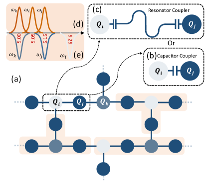
In this work, we introduce a CR architecture based on fixed-frequency transmons and fixed couplings, which can passively mitigate both quantum crosstalk and frequency-collision issues. In such architecture, transmon qubits are coupled by a bus resonator, as shown in Fig. 1(c). In particular, unlike the setting in other existing literature Chow2012 ; Sheldon2016 ; Chow2015 ; Goerz2017 , here the qubit-resonator detuning is comparable to the qubit anharmonicity and the qubit-resonator coupling is more than about an order of magnitude smaller than the anharmonicity, i.e., , retaining the dispersive condition. For the typical transmon anharmonicity of , here, the qubit-resonator coupling is below . It is, in this sense, that we nickname it the ’lightweight’ resonator coupler.
Within the architecture, the lightweight coupler allows one to address two main challenges in scaling up qubits, i.e., the speed-fidelity tradeoff imposed by crosstalk and frequency collisions due to fabrication uncertainty. For the former, as the coupler-mediated and couplings are mainly enabled by virtual transitions in subspaces with different excitations, i.e., one-excitation and two-excitation subspaces, respectively, this enables one to engineer quantum interference to mitigate coupling while retaining coupling to support fast-speed CR gates Kandala2021 ; Zhao2021 ; Goerz2017 ; Jin2021 ; Li2022 ; Zhao2022b . For the latter, to ensure fast CR gates, the other existing literature often favors the operating regime with positive control-target detunings Malekakhlagh2020 ; Tripathi2019 ; Ware2019 ; Magesan2020 . By contrast, here, even under conditions of negative control-target detunings, high-fidelity CR gates can still be achieved with gate speeds comparable to those with positive detunings. As a result, besides the positive detuning regions, the proposed architectures allow one to go beyond the existing literature by operating the qubit system in negative detuning regions, thereby mitigating the frequency-collision issue further, as illustrated, for example, in Figs. 1(d) and 1(e).
In addition, to assess the practicality, we systematically analyze the performance of the direct CX () gate Jurcevic2021 ; Malekakhlagh2022 on multi-qubit lattices and study the effect of the qubit frequency uncertainty on the gates, assuming state-of-the-art precision in setting frequencies Hertzberg2021 . We find that while crosstalk and frequency collisions for neighboring qubits can be largely mitigated, frequency collisions beyond nearest-neighbor qubits can exist due to the presence of sub-MHz couplings, and can degrade gate performance. In particular, the frequency collisions could be classified into two major types: Type-1 is the static frequency collision, such as on-resonance couplings of next-neighboring qubits can lead to the strong state hybridization, degrading individual qubit addressability; Type-2 is the dynamic frequency collision, e.g., CR drive-induced multiphoton transitions. To address such collisions, we provide an intuitive model mainly based on the dressed state picture for identifying the primary error source. Then, we show that by optimizing system parameters or adding weak off-resonant drives to selectively shift the qubits Mitchell2021 ; Wei2022 ; Noguchi2020 ; Xiong2022 ; Ni2022 ; Zhao2022c ; Wang2023 , the leading frequency collisions can be avoided.
| Layout | Capacitor coupler(a) | Resonator coupler(b) | Multipath coupler(c) | Lightweight resonator coupler(d) | |
| qubit-resonator coupling, | |||||
| qubit-resonator detuning, | |||||
| qubit-qubit coupling, | 6 | ||||
| qubit anharmonicity, | |||||
| RWA | with | without | without | with |
The rest of the paper is organized as follows. In Sec. II.1, we first provide a brief overview of CR-based transmon architectures and then discuss crosstalk and frequency collisions. In Sec. II.2, we give detailed descriptions of the introduced architecture, mainly focusing on suppression and revisiting the negative control-target detuning regime, which is previously identified as a slow gate regime. Within the architecture and assuming typical parameters, in Sec. III, we numerically analyze the performance of CX gates, including both isolated and simultaneous gates, on multiqubit lattices. Moreover, we also examine the impact of frequency uncertainty on gates. In Sec. IV, we provide discussions of frequency collisions and the resulting challenges to be faced when scaling up the architecture. Finally, in Sec. V, we provide a summary of our work.
II CR architecture with lightweight resonator coupler
In this section, for easy reference and to set the notation, we first briefly review the basic principle of CR gates and discuss the issues of ZZ crosstalk and the frequency collision in CR gate-based transmon architectures. Then, we give a detailed description of the introduced architecture and show how it can address the two issues.
II.1 Overview of the CR gate-based transmon architecture
Fixed-coupled transmons and effective Hamiltonians
The CR gate is an all-microwave-activated two-qubit gate for fixed-coupled qubits, and within the CR architecture based on fixed-frequency transmons, qubits can be fixedly coupled via a coupling capacitor or a bus resonator, as depicted in Figs. 1(b) and 1(c). Note here that for real qubit devices with capacitive coupling, besides the desired couplings, stray couplings due to, such as stray capacitances or effective capacitances mediated by coupling circuits Ku2020 ; Galiautdinov2012 ; Yan2018 ; Yanay2022 , can exist and have non-negligible contributions to interqubit couplings. By considering this, Table 1 lists four main types of architectures for coupling transmons, which can be described by the static Hamiltonian (hereinafter, )
| (1) |
| (2) |
Here and are the frequency and the anharmonicity of transmon with the annihilation (creation) operator , and is the frequency of the resonator with the annihilation (creation) operator . The interaction Hamiltonian is
| (3) |
where () denotes the strength of the coupling between the resonator (R) and qubit (), while is the direct qubit-qubit coupling strength.
Truncated to the computational subspace, the static system Hamiltonian can be approximated by an effective Hamiltonian based on the two-level qubit model and is given as Zhao2021 ; Magesan2020
| (4) |
where denote the Pauli operators and is the dressed qubit frequency. Here, the third term describes the coupling resulting from the direct qubit-qubit coupling and the resonator-mediated indirect coupling, and accordingly, the net coupling strength can be approximated by Yan2018
| (5) | ||||
where denotes the qubit-resonator detuning. The last term is coupling, which results mainly from the interactions among two-excitation subspace spanned by (hereafter, the two-qubit system state is denoted by the notation ) and is defined as DiCarlo2009 ; Galiautdinov2012
| (6) |
where denotes the eigenenergy of the static Hamiltonian Eq. (1) with eigenstate and . Note that qubit operations, such as gate operations and measurements, are commonly performed in terms of the eigenbasis of static (idle) Hamiltonians (see, e.g., Ref. Galiautdinov2012 ), hereinafter, our analysis thus takes this into consideration implicitly.
As the direct qubit-qubit coupling in general is far smaller than the qubit-resonator coupling, the coupling strength can be approximated as Zhao2021 ; Jin2021
| (7) | ||||
where is the qubit detuning and each term comes from the interaction between the qubit state and the high-energy states with the corresponding coupling strengths .
CR gate speed and ZZ crosstalk
Here we now turn to briefly review the CR gate scheme for the coupled transmons discussed above (for more details, we refer the reader to Refs. Malekakhlagh2020 ; Tripathi2019 ; Magesan2020 ). The CR gate is implemented by applying a microwave drive, i.e., CR drive, to the control qubit at the target qubit frequency. For the two-qubit system described by the Hamiltonian Eq. (1), we consider that is the control qubit while is the target, thus giving the following drive Hamiltonian
| (8) |
where is the drive frequency, and and are the drive amplitude and initial phase, respectively. For simplicity, hereafter, we have . Before going into details of CR gates based on Eq. (8), we consider a more simple drive model based on the effective two-qubit system described by Eq. (4), giving
| (9) |
As we will show, this model allows for a concise picture of the relation between CR gate speeds and crosstalk, and by combining with the following analysis based on Eqs. (1) and (8), this model will provide a direct insight into the effect of the qubit high-energy levels on CR gates.
By diagonalizing the effective Hamiltonian in Eq. (4) and then rewriting the drive Hamiltonian Eq. (9) in the eigenstates, the full system Hamiltonian can be approximated by Chow2011
| (10) | ||||
where is the dressed detuning. Here, the term denotes the off-resonance drive on the control qubit, mainly shifting the qubit frequency and thus finally contributing to a term, while the term is the core of the gate scheme, enabling CR (ZX) gates with gate speeds determined by the prefactor . Note that to mitigate the off-resonance error on the control qubit Malekakhlagh2022 , the drive amplitude is generally smaller than the qubit detuning, thus the gate speed can be limited by the interqubit coupling .
In Eq. (LABEL:eq10), as the term does not commute with the term, it can degrade CR gates. To be more specific, for the typical CR architecture with capacitor or resonator couplers (see Table 1), Eqs. (LABEL:eq5) and (LABEL:eq7) suggest that the coupling strength is typically by an order smaller than the coupling strength. And to mitigate the error induced by the term in Eq. (LABEL:eq10), the gate speed should be below . Considering these findings, typically, an coupling of can allow for a CX gate and meanwhile leads to a residual coupling of , which contributes a gate error of (note that this is only a rough estimation without considering the effect of high-energy levels on gate speeds) Kandala2021 . Moreover, the term can also cause idle errors and degrade individual qubit addressability Gambetta2012a ; McKay2019 . In this sense, the ZZ coupling acts as quantum crosstalk degrading the operational fidelity in CR architectures. Indeed, according to Eq. (LABEL:eq7), while the crosstalk can be suppressed by decreasing the interqubit coupling, this, in turn, slows down the CR gate speed. In essence, this means that there exists a speed-fidelity trade-off imposed by the crosstalk.
In the above discussion, while the effect of the high-energy levels has been taken into account in analyzing crosstalk, their effect on the CR gate speed has not been explored. Here, based on the drive Hamiltonian Eq. (8), we summarize the main results on this subject. To simplify the analysis, we consider that two transmons are coupled directly via a capacitor coupler, as indicated in Table 1, and the static system Hamiltonian is given by Eq. (1) with . Again, by rewriting the drive Hamiltonian in the eigenstates of the static Hamiltonian and then truncating to the qubit subspace, the drive Hamiltonian has the following approximate form
| (11) |
where the prefactors of the and terms are
| (12) | ||||
By expanding to the first order in , the above expressions can be approximated by Malekakhlagh2020 ; Tripathi2019 ; Magesan2020
| (13) |
From Eqs. (LABEL:eq10-LABEL:eq13), different from the result based on the two-level qubit model, there exists an additional term , which commutes with the term and thus does not degrade the CR gate and its speed. Importantly, assuming fixed , for positive control-target detunings, can have a larger magnitude than that with negative detunings, due to the negative transmon anharmonicity. As a result, to ensure fast gates, the positive detuning is favored while the negative detuning is identified as the slow gate condition Brink2018 ; Hertzberg2021 . Besides, from Eq. (LABEL:eq13), can be suppressed with large detunings. Thus, the straddling regime, i.e., Koch2007 , is often preferred for fast-speed CR gates. Note that assuming an infinite anharmonicity , the above expression reduces to Eq. (LABEL:eq10), confirming that the main difference between the result based on the two-level qubit model in Eq. (4) and the result shown here comes from the qubit high-energy levels.
Frequency collisions and Frequency allocation
The above discussions mainly focus on the most basic unit, which comprises two fixed-frequency transmons with fixed coupling, of CR-based transmon architectures. Here, we briefly discuss one of the most fundamental challenges in scaling up this architecture, i.e., frequency collisions. To start, we consider a fixed-coupled system of three transmons, labeled by , , and , as shown in Fig. 1(a), where is the control and and are targets. We further assume that the typical interqubit coupling and the detuning for control-target qubit pairs are and , respectively, and the typical CR drive magnitude is . As mentioned above, to ensure fast gates, the qubit system is operated with positive control-target detunings () in the straddling regime.
Generally, frequency collisions can be classified into two major types: the static frequency collision due to always-on couplings and the dynamic frequency collision related to CR drive-induced transitions. As in existing literature Brink2018 ; Hertzberg2021 , here we list six main types of frequency collisions, which are caused by qubit-qubit couplings with strengths of and by transitions with rates of or (to achieve high-fidelity gates, these couplings and transitions give larger collision bounds than that arising from even higher-order couplings and transitions with strengths of, e.g., and , which will be discussed in Sec. III):
(1) The static frequency collision. Because of the always-on couplings: (i) for the static systems, any degeneracy in qubit state transitions, such as , can lead to a strong state hybridization between qubits, degrading individual qubit addressability; (ii) for systems under CR drives, off-resonance drive can shift qubit frequencies and can cause qubits on-resonance with others, resulting in population swaps between qubits. For neighboring qubits with coupling strengths of , there exist two most likely cases, (S1) and (S2) .
(2) The dynamic frequency collision. This arises from unwanted transitions activated by CR drives and thus both the transition rates and the collision conditions (i.e., considering that the drive itself can stark-shift system energy levels) depend on the drive. For a CR gate applied to and , a drive at ’s frequency should be applied to . For itself, when the drive is on-resonance with its transitions, this will lead to three collisions and two of the three also cause the static collisions, i.e., (S1) and (S2) (note that depends on the specific (static or dynamic) situation, ensuing high-fidelity gates will give different bounds on ). The newly added one is (D1) the two-photon transition with the condition of . Besides, similar to , the drive can also be felt by the neighboring spectator , due to the always-on coupling between and . Thus, when ’s frequency, i.e., the CR drive frequency, is on-resonance with any transitions of , this can cause unwanted transitions of . This leads to two collision cases, i.e., (D2) the transition with , (D3) the transition with . Finally, there exists another condition (D4) , which corresponds to the drive-assisted transition .
From the above discussion, one can find that similar to the crosstalk, these frequency-collision issues mainly arise from the always-on interqubit couplings and the weak anharmonicity of transmons. More importantly, most of them can act as quantum crosstalk, limiting gate performance and imposing speed-fidelity tradeoffs. Thus, to ensure fast, high-fidelity operations for multiqubit lattices, these frequency-collision conditions should be avoided, further reducing the usable frequency range determined by the weak transmon anharmonicity. For example, assuming a typical CR gate, the qubit-qubit couplings and the rates of the drive-induced transitions are generally of the order of , thus to ensure gate error of (), the qubit system should be operated outside of the bound of about () around each frequency collision.
To this end, scaling up the CR-based transmon architectures requires a minimum of five distinct frequencies, i.e., , for square qubit lattices Brink2018 ; Hertzberg2021 ; Chamberland2020 , while for heavy-hexagonal qubit lattices, as shown in Fig. 1(a), a minimum number of three, i.e., , is required Hertzberg2021 ; Chamberland2020 . However, considering fabrication uncertainty, whether such frequency allocation can successfully mitigate frequency collisions depends on how precise in setting qubit frequencies is, as shown, for example, in Fig. 1(d). Recent studies show that, for a heavy-hexagonal qubit lattice, the state-of-the-art precision in setting frequencies allows the CR architecture to scaling up to the 100-qubit size while roughly a factor of two further improvement is needed for 1000-qubit size Hertzberg2021 . Overall, these findings suggest that frequency collision is still the major challenge for scaling up the CR-based transmon architecture.
II.2 CR architecture with passive mitigation of ZZ crosstalk and frequency collisions
As discussed above, in the context of CR-based transmon architecture, quantum crosstalk and frequency collisions are two major challenges to be faced when scaling up this architecture. In the following discussion, we will show how to passively mitigate both of two issues by introducing a promising CR architecture based on lightweight resonator couplers. Additionally, note that as mentioned before, the straddling regime is preferred to ensure fast-speed CR gates. Thus, hereafter, unless otherwise specified, we always consider this implicitly.
System Hamiltonian and ZZ suppression
As mentioned in Sec. I, in our proposed CR architecture, the fixed-frequency transmon qubits are coupled via a lightweight resonator, and the typical coupling parameters are tabulated in the last column of Table 1. For two transmons coupled via such a coupler, the static system Hamiltonian can be described by Eq. (1) with . After applying the rotating-wave approximation (RWA), the Hamiltonian is given by
| (14) | ||||
As in Sec. II.1, truncated to the qubit subspace, the above Hamiltonian can be approximated by Eq. (4) with the and the coupling strengths given as DiCarlo2009
| (15) | ||||
Note that as already mentioned in Sec. II.1, stray couplings between qubits are ubiquitous in real devices. In Appendix A, we provide specific cases for illustrating their effects on the current studied architecture and show that their presence does not change the main results based on Eq. (14). Accordingly, in the following discussion, to avoid repetition, we will focus only on the qubit architecture described by Eq. (14), in which the direct qubit-qubit coupling is not included.
From Eq. (LABEL:eq15), there are two essential features in the current architecture: (1) a -free point can exist due to the destructive interference of ZZ coupling contributing from interactions between computational state and high-energy states Jin2021 ; Li2022 ; Zhao2022a and (2) its existence does not depend on the coupling strength . The two features allow us to suppress coupling while retaining coupling. For instance, considering that when the qubit detuning is far smaller than the qubit anharmonicity (i.e., ), according to Eq. (LABEL:eq15), the ZZ-free point exists when the qubit-resonator detuning is comparable to the qubit anharmonicity, i.e., . Accordingly, the strength of the maintained coupling is about . For the typical transmon anharmonicity of and within the dispersive regime, i.e, , couplings with the strengths of can be obtained, potentially allowing fast-speed CR gates. By contrast, according to Eqs. (LABEL:eq7) and (LABEL:eq15), the expression for direct-coupled qubits is then expressed as Barends2014
| (16) |
which illustrates that no -free point exists in the direct-coupled architectures. Meanwhile, for the architecture with resonator couplers shown in Table 1, when one allows this architecture to be operated outside of the dispersive regime, i.e., quasi-dispersive regime, , the coupling can also be suppressed while maintaining even larger couplings Goerz2017 ; Li2022 . However, in this situation, besides that suppression depends strongly on system parameters (e.g., is very sensitive to small drifts in qubit and resonator frequencies), the strong state hybridization between qubits and the resonator will degrade individual qubit addressability and aggravate the frequency-collision issues.
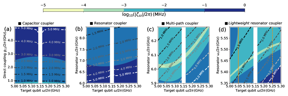
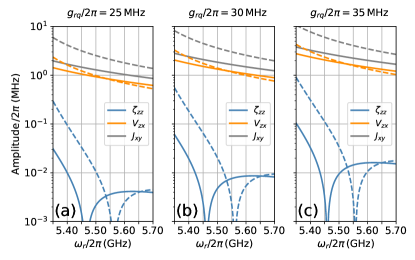
We now turn to give a more quantitative analysis of the introduced architecture. Moreover, for ease of comparison, we also show the results for the existing architectures tabulated in Table 1. Within the CR architecture, Figure 2 shows contour plots of the (the filled contours) and (the dashed contours) coupling strengths as functions of system parameters, with the control qubit frequency of and the other qubit parameters listed in Table 1. Here, according to Eq. (6), coupling strengths are extracted by numerical diagonalization of the static system Hamiltonian, while similar to Eqs. (LABEL:eq12) and (LABEL:eq13), coupling strengths are inferred from the following approximation Tripathi2019
| (17) |
To verify this, Figure 2(a) shows both the inferred values and the setting values, . One can find that the inferred values mostly agree well with the setting values. This justifies the estimation of based on Eq. (17).
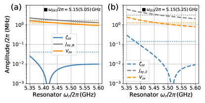
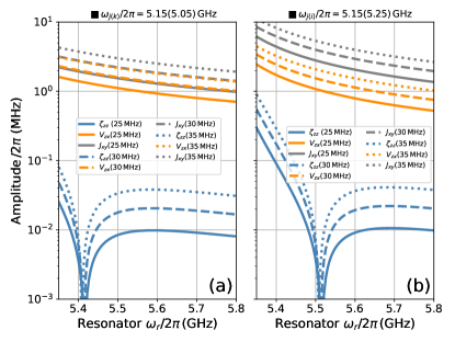
From the results shown in Figs. 2(a) and 2(b), as expected, in architectures with capacitor or resonator couplers, no ZZ-free points exist and the coupling strength is typically ten-fold smaller than that of the coupling, giving rise to . However, as shown in Fig. 2(d), for the lightweight resonator coupler, ZZ-free points exist and the coupling can be heavily suppressed in a wide frequency range while the maintained coupling strength typically ranges from to . Remarkably, compared to the capacitor and resonator couplers, this give rise to , providing at least one order-of-magnitude improvement in suppression. More specifically, vertical cuts through Fig. 2(d) at the target qubit frequencies of and are shown in Fig. 3, where dotted lines denote the results for direct-coupled qubits with the target of ensuring CX gates (assuming the CR drive amplitude of and ignoring rise-fall times). In contrast to the direct-coupled case, where the residual coupling strength is typically in the range of , the lightweight resonator coupler can allow the suppression to below , in both the positive [see Fig. 3(a)] and negative [see Fig. 3(b)] control-target detuning regions.
As shown in Fig. 2(c) and demonstrated in the previous works Kandala2021 ; Zhao2021 , similar improvements can also be available for architectures with multipath couplers. In particular, as the design of multipath couplers generally increases the circuit complexity, so their success on suppression is potentially more prone to imperfections attributable to the design itself and fabrications. Meanwhile, the result shown in Fig. 2(d) demonstrates that even with a simpler coupling circuit, suppression could still be achieved while maintaining large couplings. However, note that the lightweight resonator coupler also has its own drawbacks as well, which will be discussed in Sec. IV.
Revisiting the slow gate region
The above discussions have illustrated that with lightweight resonator couplers, crosstalk can be mitigated while maintaining large couplings. More importantly, in contrast to the cases with capacitor or resonator couplers [see Figs. 2(a) and 2(b)], here one can find a remarkably strong dependence of the coupling strength on the control-target detuning, as shown in Fig. 2(d). This can be more specific, in that as illustrated in Fig. 3, compared to that in positive detuning regions, a typical two-fold increase in can be obtained without affecting the suppression within the negative detuning regions. As expected from Eq. (LABEL:eq13), the increased coupling can compensate for the loss in gate speed due to the negative transmon anharmonicity. Therefore, fast-speed CR gates could also be available within the negative detuning regions, which have previously been identified as forbidden zones with slower gate speeds Brink2018 ; Hertzberg2021 .
The origin of the above appealing features can be rationalized by noting that from Eq. (LABEL:eq15), when the qubit-resonator detuning is comparable to the qubit-qubit detuning (as in the currently studied architecture), i.e., , will depend strongly on the detuning sign. By assuming a fixed control qubit frequency, having negative control-target detunings means that the detuning between the resonator and the target qubit is smaller than that with positive detunings, enabling larger resonator-mediated couplings. By contrast, if (as in the architecture with resonator couplers), whether the detuning changes its sign, there is little effect on , as shown in Fig. 2(b). Therefore, in architectures with capacitor and resonator couplers, to increase coupling, one has to increase the direct coupling or the qubit-resonator coupling and this will inevitably increase couplings. For example, under the conditions with negative detunings, to ensure gate speed comparable to that in the positive detuning regions, the direct coupling strength should be increased from to and accordingly, the coupling will increase from to , as shown by the dotted lines in Fig. 3. This further explicitly explains why the negative detuning is previously identified as the slow gate condition Brink2018 ; Hertzberg2021 . On the contrary, here all the benefits from the increased coupling can be achieved without sacrificing suppression. Additionally, Figure 2(c) also shows similar appealing behavior, suggesting that the multipath coupler can be an alternative for achieving fast gate speed in negative detuning regions.
In particular, Figure 3 also shows the rate as a function of the resonator frequency. Here, according to Eq. (LABEL:eq12), is determined by
| (18) |
with the assumption of the CR drive magnitude . As expected, even under the condition of negative detunings, the resulting rate is comparable to that within the positive detuning regions. While here the typical rate is about , allowing CX gates without rise-fall times, even higher rates may be possible by increasing the qubit-resonator coupling . However, increasing generally will increase the residual couplings. For example, when increasing the qubit-resonator coupling from to , the typical rate becomes while the typical coupling has increased to (see Appendix B for details). Given the state-of-the-art gate performance is still limited by qubit decoherence, presently unitizing larger qubit-resonator couplings could help increase the gate speed and reduce the incoherent error. This highlights the importance of balancing incoherent errors and coherence errors arising, for example, from crosstalk, to achieve high-fidelity gates.
Below, to provide a more direct verification, we turn to study the implementation of gates within the introduced architecture. In particular, we will focus on both the conditions of positive and negative control-target detunings. Here, based on the CR gate scheme, we consider the realization of direct CX gates Jurcevic2021 ; Malekakhlagh2022 . Besides the CR drive on the control qubit, here, an additional cancelation drive is also applied to the target qubit at its frequency. This additional drive is introduced to ensure no operation on the target qubit when the control qubit is in state Malekakhlagh2022 . Accordingly, within the RWA, the drive Hamiltonian can be expressed as
| (19) |
where denotes the amplitude of the drive on . Hereafter, we consider using the cosine-decorated square pulse with fixed ramp times of , which is defined as
| (20) |
where denotes the peak drive amplitude, is the ramp time, and represents the gate length. A detailed procedure on the gate tune-up and the characterization for the CX gate can be found in Appendix C.
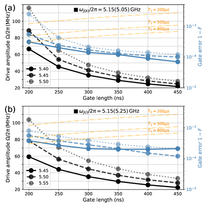
Figure 4 shows both the CX gate error (intrinsic error, i.e., excluding the gate error from qubit incoherence) Pedersen2007 and the CR drive amplitude as functions of the gate length with varying resonator frequencies. As expected from the above analysis, under the conditions of negative detunings, high-fidelity CX gates can still be achieved with a gate speed comparable to that within the positive detuning regions. Moreover, the results shown in Fig. 4 also illustrate that within the typical range of drive amplitude, gates with gate errors approaching could be obtained with a gate length of . In addition, as studied in previous works Motzoi2009 ; Gambetta2011 ; Li2023 ; Malekakhlagh2022 , by optimizing drive parameters, the pulse ramp time can be shorter and the off-resonance error due to the CR drive can be further suppressed. Moreover, as mentioned before, even higher rates (e.g., , allowing for a CX gate with a ramp time of ) can be obtained by increasing the qubit-resonator coupling. Meanwhile, the resulting coupling can be suppressed below , contributing to the gate error at the level of Kandala2021 . Thus, CX gates with even faster gate speed and higher gate fidelity should be possible within the currently studied CR architecture.
Furthermore, in Fig. 4, we also show the incoherence error versus the gate length for the CX gate. Here, the coherence times are assumed to be the same for both the control and target qubits with Malekakhlagh2022 ; Kim2023 , and the incoherence error can be estimated by Malekakhlagh2022 . One can clearly see from Fig. 4 that there exists a trade-off between the intrinsic (control) gate error (mainly dominated by the control error from the off-resonance CR drive) and the incoherence error. Given the state-of-the-art coherent times of fixed-frequency qubits Place2021 ; Wang2022 ; Gordon2022 , the gate error should be limited by the qubit incoherence in both the negative and positive detuning regimes.
As in various qubit architectures with superconducting qubits, gate speeds and operational performance generally hinge on the ability in setting qubit parameters. Specifically, in the currently studied CR architecture and for fixed resonator-qubit couplings (see Figs. 3 and 4), the gate speed is mainly determined by the qubit-resonator detuning. Accordingly, assuming the drive amplitude of , to ensure CX gates (with a ramp time of ), the usable range of the qubit-resonator detuning is about for the positive detuning case while it reduces to about for the negative detuning case, as shown in Figs. 3 and 4. In contrast to the architecture with resonator couplers, where the coupling (thus also the CR gate speed) shows less sensitivity to the variation in qubit-resonator detuning, see Figs. 2(b), this generally introduces an additional constraint for achieving fast-speed CR gates. However, as illustrated in Appendix B, increasing resonator-qubit couplings could help relieve this constraint. Moreover, since currently the reproducibility of the resonator frequency is much better than that of qubits (see, e.g., Ref. Norris2023 ), this constraint could be largely addressed by improving the accuracy in setting qubit frequencies (as for addressing the frequency-collision issue, but with less stringent requirements on accuracy).
Given the above illustration of fast-speed CX gates in the negative detuning region, we now go back to the frequency-collision issue. As discussed in Sec. II.1, the qubit frequency allocation should be optimized to balance gate errors due to frequency collisions and incoherence errors resulting from slow gate speeds. Since currently, gate performance is most likely to be limited by qubit decoherence, the positive detuning region is preferred for ensuring fast-speed gates. However, this in turn decreases the usable range of qubit detunings, making the frequency-collision issue more prominent. Thus, mitigating frequency collisions and improving the collision-free yield of large-size systems put stringent requirements on the accuracy in setting qubit frequencies Brink2018 ; Morvan2022 ; Hertzberg2021 . Even with sparse connectivity, e.g., the heavy-hexagonal lattice topology shown in Fig. 1(a), the state-of-the-art accuracy is still not enough to support -qubit systems Hertzberg2021 . Within the current studied CR architecture, we show that fast-speed gates are also available in the negative detuning regions, extending the usable detuning range. As a consequence, we expect that this could largely mitigate the frequency-collision issue and relax the stringent requirement on the accuracy for scaling up to large system sizes.
III Crosstalk mitigation in multiqubit systems
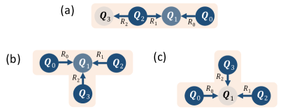
In this section, to examine the practicality of the architecture, we intend to investigate the CX gate performance and the impact of quantum crosstalk on it in the typical four-qubit units of the heavy-hexagonal qubit lattice, as shown in Fig. 5. Then, we turn to give schemes mitigating the crosstalk effect on gates. As shown in Fig. 1(e), unlike in other existing literature [see Fig. 1(d)], here the three-frequency pattern is given as . Following the above discussion, here we consider that the desired control frequency is while the target qubit frequency is . This frequency allocation scheme is expected to mitigate the frequency-collision issue within the current architecture, as illustrated in Figs. 1(d) and 1(e).
In the following discussion, we first study the gate performance of isolated CX gates in the four-qubit systems and then turn to study the simultaneous gates. Moreover, we also provide a preliminary study to determine the effect of frequency variations on suppression and gate performance.
| Layout | |||||||
|---|---|---|---|---|---|---|---|
| ’’-shape | 5.15 | 5.40 | 5.05 | 5.41 | 5.14 | 5.47 | 5.25 |
| ’’-shape | 5.15 | 5.40 | 5.05 | 5.41 | 5.14 | 5.39 | 5.16 |
| ’’-shape | 5.14 | 5.47 | 5.25 | 5.48 | 5.15 | 5.49 | 5.16 |
III.1 Error analysis with typical qubit parameters
Isolated CR gates
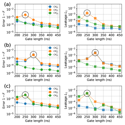
Given the system parameters listed in Table 2, Figure 6 shows both the isolated gate error and leakage Wood2018 as functions of the gate length for the three four-qubit systems shown in Fig. 5. Here, the ZZ coupling between near-neighbor qubits ranges from and and is expected not to limit the following CX gate performance. Note that hereafter the isolated gates are characterized by assuming all the spectator qubits in their ground states Zhao2022a , see Appendix C for more details.
From the result shown in the left panels of Fig. 6, as expected, increasing the gate length can generally reduce gate errors (mainly due to the off-resonance CR drive Li2023 ; Malekakhlagh2022 ). However, unlike isolated two-qubit systems (see Fig. 4), the gate error can show spikes (highlighted by black circles) at specific gate lengths, which is coincident with the increase of leakage, as shown in the right panels of Fig. 6. For instance, in Fig. 6(a), the gate error of shows a spike at the gate length of , coinciding with the peak of leakage. This suggests that the spikes of the gate error dominantly arise from leakage related to spectator qubits.
Inspired by the crosstalk analysis of baseband flux-based gate operations Zhao2022a , here we use a similar approach based on the dressed states picture to identify the leading source of the isolated gate errors. Note that here we focus only on the driven system with a single drive frequency while for driven systems with multiple distinct drive frequencies (i.e., related to simultaneous CR gates), the analysis given in Floquet theory could be devised for this purpose Chu2004 ; Heya2023 ; Zhang2019 ; Gandon2022 . By moving into the rotating frame at the CR drive frequency and within the RWA, the full system Hamiltonian, for example, describing the implementation of on the four-qubit system shown in Fig. 5(a), can be expressed by
| (21) | ||||
with the qubit and the resonator labeled by and , respectively. Here, to simplify the discussion, we neglect the cancelation drive term [see Eq. (19)].
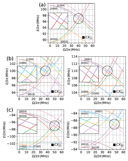
By numerical diagonalization of the Hamiltonian in Eq. (21), Figure 7(a) shows the dressed eigenenergies of the ’’-shape four-qubit system under the drive on as a function of the CR drive amplitude. One can find that near the drive amplitude of , there exist level anticrossings arising from the resonance interaction between and its next-near-neighbor with the strength of (in line with the strength of the next-nearest neighbor interaction mediated by ). Meanwhile, for with the gate length of shown in Fig. 6(a), the peak drive amplitude is about [see also in Fig. 4(a)]. These two observations indicate that during the implementation of - , the qubit system is operated nearby the anticrossing, thus enabling the population swap between and and causing the increase in leakage and gate errors. By contrast, for shorter gates (e.g., ) or slower gates (e.g., ), the qubit system is operated far away from the anticrossing, allowing the suppression of the population swap. In this situation, the gate error and leakage will be restored to the level, which is limited mainly by the off-resonance error within the isolated two-qubit system itself, as illustrated in Fig. 6(a).
Similarly to , the spikes of gate error and leakage in the ’’-shape and ’’-shape four-qubit systems, as shown in Figs. 6(b) and 6(c), also arise due to the parasitic interactions between the control qubits and their next-near-neighbor qubits, highlighted in Figs. 7(b) and 7(c). Thus, in essence, the increased gate errors shown in Fig. 6 are caused by the static frequency collision resulting from the next-nearest-neighbor interaction, as discussed in Sec. II.1.
Modeling the formation of frequency collisions
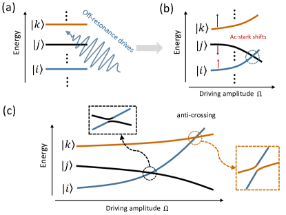
To get further insight into the underlying physics of the above collision processes, we consider a more intuitive model based on the dressed state picture. For a multi-level quantum system under an off-resonance drive, as shown in Fig. 8(a), moving into the rotating frame at the drive frequency gives a dressed multi-level system, whose spectrum as a function of the drive amplitude is sketched in Fig. 8(b). Through the ac-Stark effect, the off-resonance drive can shift the levels lower or higher in frequency, which is determined by whether or not the drive is blue-detuned or red-detuned from the transitions in the multi-level system. As a consequence, by increasing the drive amplitude, one shifted level can sweep through the other shifted one, as shown, for example, in Fig. 8(b). Furthermore, when the two levels are coupled together, there can exist a level anticrossing, whose size is determined by the coupling strength, at the resonance point, as shown in the inset of Fig. 8(c).Basically, these two factors together lead to the formation of frequency collisions. In this context, according to the primary mechanism underlying the coupling, the frequency collision can be classified into static and dynamic, as discussed in Sec. II.1.
Similar to the above model, in the context of CR gate architecture, the off-resonance CR drive will shift the control qubit frequency, causing accidental frequency collisions between the control qubit and its neighbors. Specifically, we consider the collision process underlying the results shown in Figs. 6 and 7. As listed in Table 2, the typical magnitude of the control-target (i.e., near-neighboring qubit pairs) detuning is while the control qubit and its next-near neighbors (i.e., another control qubit) are only detuned by . Thus, given the typical drive amplitude of and the detuning magnitude of , the ac-Stark shift can be approximated by Schneider2018
| (22) |
giving rise to and for the positive and negative detuning conditions, respectively. Moreover, the control qubit and its next-near neighbors, e.g., and in Figs. 6(a) and 7(a), can be coupled via the mediator, e.g., , with the typical strength of (see also in Sec. II). Given these considerations, the static frequency collision due to the on-resonance coupling between neighboring control qubits can explicitly explain the presence of the spikes in gate errors and leakage at specific drive amplitudes shown in Fig. 6.
In essence, this frequency collision is caused by the always-on qubit-qubit couplings (in this sense, we call it static frequency collision). But the condition for the occurrence of such collision depends on the CR drive amplitude (gate length). This in turn allows one to avoid such collision issues by optimizing drive amplitudes (gate lengths), as suggested in Fig. 6.
Simultaneous gate operations
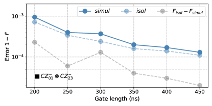
To further examine whether there exists additional quantum crosstalk for implementing CX gates in parallel, here we provide an analysis of the fidelity of simultaneous CX gates Zhao2022a . With the typical parameters listed in Table 2, Figure 9 shows the performance of simultaneous gates () in the ’’-shape four-qubit system shown in Fig. 5(a). Here, by adding the errors of the constituted isolated gates and , we also show the isolated gate errors and the added errors () when gates are implemented in parallel. Similar to isolated gates (see Fig. 6), increasing the gate length can reduce the simultaneous gate error. Moreover, the typical added error is below , suggesting that there exists no additional quantum crosstalk that contributes significantly to gate errors. This shows that within the currently studied CR architecture, high-fidelity simultaneous gates may be possible, but as we will show, this is far from the whole story. We will go back to this subject in the following section.
III.2 Challenging from fluctuations in qubit parameters
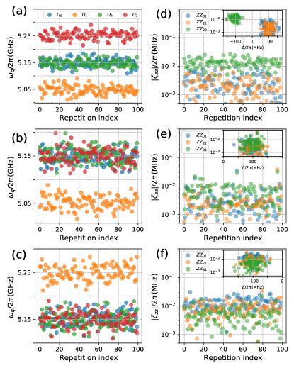
Below, to study the effect of frequency uncertainty on the currently studied architecture, we consider that control and target qubit frequencies are randomly distributed around their designed values, i.e., the control frequency of and the target frequency of , with the standard deviation of Hertzberg2021 . With distinct repetitions, we provide analysis of both the suppression and the performance of gates (including both isolated gates and simultaneous gates) for the four-qubit systems shown in Fig. 5. Accordingly, Figures 10(a)-(c) show the qubit frequencies of repetitions for the four-qubit systems shown in Figs. 5(a)-(c).
suppression
As shown in Figs. 3, for isolated two-qubit systems with the desired setting in qubit frequencies, the coupling can be suppressed below . However, as we will show, the deviation from the target setting in multi-qubit systems will make the suppression more complicated.
Figures 10(d)-(f) show the ZZ couplings of repetitions and the maximum (median) values of the coupling are , , and for the four-qubit systems shown in Figs. 5(a)-(c), respectively. Moreover, it is also shown that the ’exceptional’ points with large couplings almost appear in pairs, as shown in Fig. 10(e). To check their dependence on the qubit frequencies, the inset also shows the distributions of the ZZ coupling over the control-target detunings. We find that these ’exceptional’ points arise mainly from static frequency collisions due to interactions between next-nearest-neighboring control qubits.
To be more specific, similar to the frequency collision of (S1), when the control qubit is on-resonance with its neighboring control qubit, the strong state hybridization due to the next-nearest-neighboring couplings can degrade qubit addressability and result in prominent quantum crosstalk. This is reasonable as the frequencies of all the control qubits are distributed around the same value, making them more prone to this frequency-collision issue. For instance, in Fig. 10(e), the maximum coupling of is caused by the nearly on-resonance coupling of neighboring control qubits and . By excluding these ’exceptional’ points arising from these static collisions, we find that the typical coupling could be below . Similar to the deterioration of suppression, as we will show, such collisions can also limit the CX gate performance and cause spikes of gate errors appearing in pairs.
Isolated CX gates
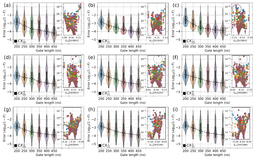
The violin plots in Fig. 11 show the distributions of isolated CX gate errors with varying gate lengths. Similar to isolated two-qubit systems (see Fig. 4), here the median gate errors (indicated by dashed lines) are reduced by increasing the gate length and the typical gate error ranges from to . Moreover, as shown in the inset of Fig. 11, when increasing the gate lengths, almost all qubits show decreasing trends in gate errors, suggesting that the gate error mainly comes from the CR drive. Besides, three main types of features deserve to be discussed in more detail.
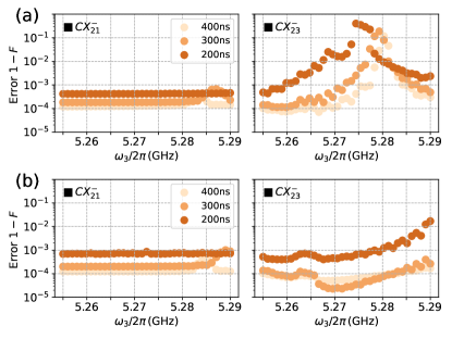
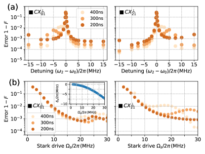
(i) As shown, for example, in Fig. 11(a), under the positive detuning condition, large gate errors can be found near the detunings of and . Following the discussion in Sec. II.1, here the gate error is mainly dominated by the off-resonance transitions, i.e., the transition and the two-photon transition of the control qubit, which correspond to the frequency collisions of (S1) and (D1). As expected, prolonging the gate length (i.e., decreasing the drive amplitude) or increasing ramp time (i.e., mitigating non-adiabatic transitions in the dressed picture, as discussed in Sec. III.1), these transitions can be suppressed. Furthermore, as already discussed in previous works Li2023 ; Malekakhlagh2022 , we expect that off-resonance errors shown in Fig. 11 can be largely suppressed by optimizing the control pulse shape in Eq. (20).
In addition, as shown in Figs. 11(g)-(i), under the negative detuning conditions, large gate errors can also be found near the detunings of . Similar to that within positive detuning conditions, this arises from the transition related to the frequency collision (S1). Meanwhile, in contrast, as here the control-target detuning is negative, the two-photon transition is significantly suppressed by the large detuning of . Thus, with the negative detuning condition, the frequency-collision issue of (D1) can be safely omitted for ensuing high-fidelity gates.
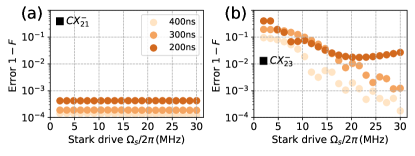
(ii) Similar to the prominent crosstalk, indeed, the static collision arising from on-resonance coupling of neighboring control qubits can account for the spikes of gate errors appearing in pairs, as highlighted, for example, by the grey circles in Figs. 11(d)-(f). More importantly, different from the dynamic collisions and the static collision discussed in Figs. 6 and 7, the current collision is almost independent of the CR drive, explaining why the resulting gate errors are not reduced by increasing the gate length, as shown in Figs. 11(d)-(f). More specifically, Figure 12(a) shows the CX gate errors versus the detuning between neighboring control qubits with different gate lengths for a subsystem (consisting of , , and ) of the ’’-shape qubit system. One can find that when the two control qubits are on-resonance, the spikes of gate errors appear in pairs (see the left and right panels) and peak values are almost independent of the gate length. Additionally, it is also shown that since the typical coupling strength between neighboring control qubits is of the order of (see in Sec. III.1), a small detuning from the frequency collision, i.e., , is adequate to ensure gate error of ().
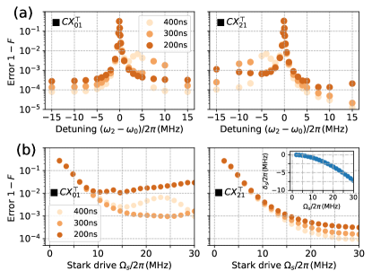
Besides, as one might expect, the on-resonance coupling of control qubits can lead to worsening qubit addressability and will inevitably complicate almost all qubit operations (such as qubit readout), not only restricted to gate operations. It is in this sense that we argue that this type of static frequency collision deserves to be addressed with a high priority. In the current CR architecture, to avoid such static collision, one possible approach is by adding an additional always-on off-resonant drive to selectively shift qubits Zhao2022c ; Wei2022 . As shown in Fig. 12(b), by applying a stark drive to with the detuning of , ensuring gate errors of only requires an amplitude of . As shown in the inset of Fig. 12(b), this drive induces a frequency shift of , agreeing well with the estimated collision bound [see Fig. 12(a)]. Additionally, as already studied in the previous work Zhao2022c , the Stark drive itself could also introduce additional error sources, this can explain why generally the performance of is worse than that of , as shown in Fig. 12(b). Moreover, with the mitigation of the frequency-collision issue, the qubit addressability could be improved and high-fidelity readout could also be possible, even under the always-on off-resonance drive Zhao2023 ; Chen2022 . Similarly, as shown in Figs. 11(g)-(i), such static collision issues also exist for the ’’-shape system, and, in Appendix D, we also show the results for addressing this issue based on the ac-Stark effect.
(iii) Compared to other existing CR architectures listed in Table 1, the most peculiar feature of the currently studied architecture is that the magnitude of the qubit-resonator detuning is comparable to that of the control-target detuning, as well as that of the qubit anharmonicity. This can raise a crucial question, whether this setting will introduce an additional leakage channel or error source. To answer that question, similar to the discussion of frequency collision for qubits given in Sec. II.1, it should be necessary to analyze the frequency-collision issue associated with both the qubits and the resonators, which could potentially cause leakage and gate errors. Since the typical detuning between the qubit and its resonator coupler is larger than , frequency collisions similar to that given in Sec. II.1, i.e., (S1-S2) and (D1-D4), can be ignored for the present purpose. Moreover, as it is generally assumed that all the resonator couplers are initialized in their ground states, the frequency collision should be enabled by the CR drive-induced multiphoton process, thus acting as a dynamic one.
Accordingly, considering the present frequency setting (i.e., ) and the typical parameters listed in Table 2, we can expect that the leading frequency collision should satisfy the following relation (see Appendix E for details)
| (23) |
This describes the two-photon transition in the coupled qubit-resonator system, wherein the state is denoted by , and the transition rate can be approximated by (applying second-order perturbation theory) Tripathi2019 ; Nesterov2021 ; Poletto2012
| (24) |
Similarly, the two-photon transition with the condition of can occur, but the transition is heavily suppressed by the large qubit-resonator detuning and the negative anharmonicity of transoms in our setting Zhao2022a (see Appendix E for details).
Indeed, the dynamic frequency collision causes the spikes of gate errors highlighted by the black circle in the inset of Fig. 11(c). To provide a more detailed analysis of the collision issue, Fig. 13(a) shows the gate errors as a function of for a subsystem (consisting of , , and ) of the ’’-shape qubit system. As expected [see Eq. (34)], the presence of this dynamic collision does not affect the performance of while it can significantly degrade the gate performance. Moreover, it also illustrates the typical features of dynamic frequency collisions, i.e., both the collision condition and the induced gate error (transition rate) show a dependence on the CR drive amplitude (gate length). This suggests that, to avoid the detrimental impact of such collision, one can optimize the gate length, similar to the case discussed in Fig. 6. Besides, according to Eq. (34), increasing the resonator frequency can be an alternative approach for this purpose, as shown in Fig. 13(b), which shows the CX gate errors with a larger resonator frequency. Additionally, in Appendix D, we also show that such collisions can also be mitigated through the ac-Stark shift, similar to the one illustrated in Fig. 12(b).
Simultaneous CX gates
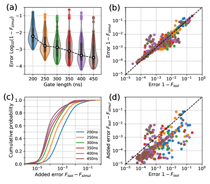
Here, we turn to study CX gates implemented in parallel, especially focusing on simultaneous CX gates in the ’’-shape four-qubit system shown in Fig. 5(a). In Fig. 14(a), the violin plot shows the distributions of simultaneous gate errors versus the gate length. Similar to that shown in Fig. 9, the median gate errors (indicated by dashed lines) decrease when increasing the gate length, in line with the expectation that the dominant gate error comes from the CR drive. Moreover, the simultaneous gate errors show a clear linear dependence on the isolated gate errors, as shown in Fig. 14(b).
Besides, a close look at Fig. 14(b) also shows us that while the simultaneous gate performance is generally worse than that of the isolated one, in some cases (especially for isolated gates with the fidelities limited by leakage), the simultaneous gate can show better performance. As already noted in the previous work Zhao2022a , here the isolated gates are characterized by assuming spectator qubits in ground states. Thus leakage occur during isolated gate operations (such as, see Fig. 6, when qubits are on resonance with spectator qubits) will contribute to the control error of simultaneous gates. In this sense, the presence of such a situation is partly due to our ill-defined metric and thus the added error is only indicative. Excluding such cases, Figure 14(c) shows the cumulative distribution of the added gate errors . It is shown that the median added error is below and can further reduce by increasing the gate length. For instance, with a gate length of , the median error can be suppressed below .
To further evaluate the effect of quantum crosstalk residing in the currently studied architecture, in Fig. 14(d), we also show the distributions of added errors over the isolated gate errors. One can find that in almost all the cases, the added errors are smaller than that of the associated isolated gates. This suggests that in the currently studied architecture, there exists no additional quantum crosstalk that contributes significantly to gate errors for gates implemented in parallel.
IV Discussion
In this section, we briefly summarize the main frequency-collision issue in the currently studied CR architecture and give potential approaches to address this issue. Then, we provide a discussion of parameter sensitivity in the current architecture.
Revisiting the frequency collision issue
As discussed in Sec. II.1 and Sec. III, according to the underlying mechanism, the frequency collision can be classified into two main types, static and dynamic. Accordingly, near frequency-collision regions, the two types of collisions can be described by the following effective two-level Hamiltonian given in the dressed state picture (see Fig. 8)
| (25) |
| (26) |
where and are for describing the static and the dynamic collisions, respectively. Here, () denotes the two-level detuning without the CR drive while () is the ac-Stark shift, generally displaying a quadratic dependence on the drive amplitude [see Eq. (22)]. denotes the coupling enabling the static collisions and is almost independent of the drive amplitude, while is the coupling for the dynamic collision and strongly depends on the CR drive amplitude. Below, based on Eqs. (25) and (26), we give more detailed discussions on the frequency collision:
(i) The static frequency collision. As in Eq. (25), the static collision and the associated frequency bound mainly depend on the static couplings , such as couplings between near-neighbors or beyond. To mitigate such collisions, a finite detuning of should be retained with the highest priority. Otherwise, this will worsen qubit addressability and significantly complicate almost all of the qubit operations. On the other hand, even with the predefined detuning , the CR drive can shift qubits, giving rise to the additional detuning . This means that the on-resonance condition can be achieved at specific drive amplitudes, as shown in Figs. 6 and 7. Thus, to further avoid such situations, the drive amplitude (gate length) should be optimized, keeping away from the on-resonance point (see Figs. 6 and 7). In the currently studied CR architecture, the collision issue for neighboring qubits can be largely mitigated by using the three-frequency allocation scheme on the heavy-hexagonal qubit lattice, as illustrated in Figs. 1(a) and 1(e). However, given the three-frequency pattern, neighboring control qubits are prone to such collision issue. Hopefully, the typical coupling is at the level of sub-MHz, thus, according to Eq. (25), a small detuning is adequate for addressing such issues [see Fig. 12(a)]. Meanwhile, even without the predefined detuning , adding a weak off-resonant drive to selectively shift qubits can mitigate this issue, as demonstrated in Fig. 12(b).
(ii) The dynamic frequency collision. From Eq. (26), both the detuning and the coupling depend on the CR drive amplitude Zhang2019 . In essence, this issue is generally manifested as drive-induced single- or multi-photon transitions, which are absent when the drive is turned off, and the main types are summarized in Sec. II.1. Accordingly, both the resulting gate error and the occurrence condition can show a clear dependence on the drive amplitude, as shown, for example, in Fig. 13(a). Thus, generally, to mitigate the issue, one can keep a predefined detuning and decrease the drive amplitude. On the other hand, besides improving the accuracy in setting , one might prefer to optimize the control pulse for ensuring fast-speed gates Li2023 ; Malekakhlagh2022 . In the dressed state picture, this corresponds to suppressing the non-adiabatic transitions which are dominated by the collisions with large couplings. Note that similar to baseband flux-control gate operations Zhao2022a , in the long term, one should balance gate errors due to frequency collisions with small couplings (sub-MHz, favoring fast gates) and with large couplings (few MHz, preferring slow gates).
In the present architecture based on heavy-hexagonal layout and the allocation scheme shown in Figs. 1(a) and 1(e), the dynamics-collision issue for neighboring qubits can be largely mitigated by assuming the state-of-the-art accuracy in setting qubit frequencies Hertzberg2021 , as shown in Fig. 10. But indeed, new frequency collisions can be introduced here, as indicated by Eq. (34), due to the small qubit-resonator detuning (note that as shown in Fig. 2(c), within the architecture with the multipath coupler, this issue should be heavily suppressed). In Fig. 13(b), we show that increasing the resonator frequency, i.e., increasing in Eq. 26, can address this issue while it does not seriously affect the gate speed [see also Fig. 4(a)]. Additionally, as illustrated in Appendix D, this issue can also be mitigated by adding off-resonance drives. Note that, unlike the static collision, here the dynamics collision is activated by the CR drive. Thus, in principle, the off-resonance drive could only be applied during gate operations Zhao2022c ; Wang2023 , rather than being applied in an always-on manner. In this scenario, to ensure high-fidelity state maps between the computational basis and microwave-dressed basis, the Stark drive should be slowly ramped up or down Zhao2022c .
Parameter sensitivity
As illustrated in Sec. II and Sec. III, in the currently studied architecture, the realization of fast-speed CR agates with suppression depends strongly on the accuracy in setting qubit parameters. For instance, assuming the control-target detuning of and the coupling suppressed below , the typical usable range of qubit-resonator detuning for ensuring fast-speed gates (here we consider that, assuming a CR drive amplitude of , the target rate is ), is only about , as shown in Figs. 2(d) and 3. Considering the fabrication uncertainty, within the current architecture, ensuring the successful realization of fast gates with suppression should be a non-trivial task.
Generally, there are two kinds of solutions for this issue: (i) Optimizing system parameters. For instance, by increasing the qubit-resonator coupling, the useful regime can increase to with the coupling suppressed below (see Fig. 16 in Appendix B). In addition, decreasing the control-target detuning could be an alternative approach, but to ensure high-fidelity gates, the detuning should be far away from the on-resonance condition (S1). (ii) Adjusting qubit or resonator parameters after fabrication. For example, similar to the mitigation of the frequency-collision issue, this issue can be largely addressed by improving the precision in setting qubit frequencies with the laser-annealing techniques Hertzberg2021 ; Zhang2020 . Besides, given that the frequency reproducibility of resonators can be far better than that of qubits (see, e.g., Norris2023 ), the qubit and the resonator coupler could be placed in separate chips within flip-chip architectures. As a consequence, each qubit can have its dedicated resonator coupler for realizing a fast-speed gate with suppression.
V conclusion
We introduce a CR architecture based on fixed-frequency transmons and fixed qubit-qubit couplings for mitigating both quantum crosstalk and frequency-collision issues. Within the CR architecture, we show that the proposed lightweight resonator coupler allows us to address the speed-fidelity tradeoff issue imposed by quantum crosstalk and extend the usable operating region with sizable couplings. Given typical qubit parameters, we demonstrate, both analytically and numerically, that quantum crosstalk can be suppressed and fast-speed, high-fidelity CR gates can also be achieved with the condition of negative control-target detunings.
Accordingly, we movebeyond the existing literature by operating the qubit system at both the positive and negative detuning regions. This could largely mitigate the frequency-collision issue in existing architectures. To assess the feasibility and utility, assuming the state-of-the-art precision in setting frequencies, we systematically analyze the CX gate performance in the proposed architecture and show that quantum crosstalk and frequency-collision issue can be largely mitigated, while the remaining collision issue can be addressed by adding weak off-resonance drives. This suggests that the architecture proposed here could be feasible, even considering practical challenges, especially fabrication uncertainties.
Although here we mainly focus on the heavy-hexagonal layout, one can reasonably expect that within the introduced CR architecture, the quantum crosstalk and the frequency-collision issues in square qubit lattices can also be suppressed. However, as studied in previous works Hertzberg2021 ; Chamberland2020 , to avoid frequency collisions and to improve the fabrication yield, more stringent requirements, especially in setting the qubit frequency, would be required for the square layout than for the heavy-hexagonal layout.
To further improve gate performance and mitigate frequency collisions, we give an intuitive model based on the dressed state picture. Accordingly, we illustrate the general underlying mechanism of frequency collisions and show that frequency collisions can be classified into two main types, i.e., static and dynamic. We further provide dedicated schemes to mitigate the two types of frequency collisions. While the analysis focuses on the CR architecture with transmon qubits, we expect that these discussions could also be useful for other qubit architecture with all-microwave-activated gate operations Mitchell2021 ; Wei2022 ; Nesterov2021 ; Xiong2022 .
Supporting long coherence times and low control overhead while protecting the qubit system from quantum crosstalk effects should be one of the most crucial steps toward large-scale quantum processors based on fixed-frequency qubits and fixed couplings. The present work could be helpful in guiding the design of CR gate-based architectures for this purpose.
Acknowledgements.
The author would like to thank Pei Liu, Yingshan Zhang, and Ziting Wang for many helpful discussions on the CR gate-based transmon architecture. Thanks also go to Meng-Jun Hu, Zhikun Han, and Fei Yan for their insightful comments, especially about the time stability of qubit performance in superconducting quantum processors. The author would also like to thank Guangming Xue, Peng Xu, and Haifeng Yu for their generous support and encouragement. The author gratefully acknowledges support from the National Natural Science Foundation of China (Grant No.12204050) and the Beijing Academy of Quantum Information Sciences.Appendix A Parasitic interactions and their impact on the CR architecture
As mentioned in Sec. II.1, stray couplings between qubits are ubiquitous in real superconducting qubit devices. Here, we turn to provide specific cases for illustrating their effects on suppression and rates. As mentioned in the second column of Table 1, we consider a direct qubit-qubit coupling arising from an effective capacitance Ku2020 ; Galiautdinov2012 , giving rise to . By including such direct qubit-qubit coupling terms, we go back to the generalized system model described by the Hamiltonian in Eq. (1). Following Eqs. (6), (LABEL:eq12), and (17), in Fig. 15, we show the coupling, coupling, and the rate as functions of the resonator frequency with different the qubit-resonator couplings. Here, the used parameters are the same as in Fig. 3.
It is shown that considering the direct couplings, suppressing couplings and maintaining couplings with sizable strengths can still be achieved. While for the given qubit-resonator coupling, both the () coupling and the rate strength are reduced compared to that without taking into account the stay coupling (see Figs. 15(a) and 3), increasing the qubit-resonator coupling here should be a practical solution to such concern, as shown in Fig. 15(b). Moreover, the usable frequency range is comparable to that shown in Fig. 3.
Appendix B Effect of the increased qubit-bus coupling on the CR architecture
Within the proposed CR architecture, as mentioned in Sec. II.2, increasing the qubit-resonator coupling could be a practical solution to further improve the rate, as well as the usable parameter range. Meanwhile, this can also give rise to larger couplings. Figure 16 shows the effective interqubit couplings ( and couplings) and rates versus the resonator frequency with different qubit-resonator couplings. It is shown that when increasing the qubit-resonator coupling, both the rate and the useful range of the qubit-resonator detuning can also be enhanced. However, for instance, increasing the qubit-resonator coupling from to , accordingly, will increase the typical coupling from to . On the other hand, similar to the multipath coupler Kandala2021 ; Zhao2021 , even in these cases, the typical magnitude of can still reach the order of , suggesting that the proposed architecture can still outperform other existing architecture, such as architectures with capacitor couplers or resonator couplers [see Figs. 2(a) and 2(b)].
Appendix C The tune-up procedure and characterization of the direct CX gate
In the present work, we consider the implementation of the direct CX gate by simultaneously driving both the control qubit and the target qubit , as described by the drive Hamiltonian given in Eq. (19). As mentioned in Sec. II.2, the used pulse shape is a cosine-decorated square pulse with fixed ramp times of , given in Eq. (20). For tuning up CX gates with a fixed gate length of , we consider numerically optimizing the two drive amplitudes , which are the peak drive amplitudes of the two applied drives [see Eq. (20)], and the used loss function is defined as
| (27) |
where () denotes the population in state () after the gate operation with the system initialized in state (). Here, denotes the eigenstate of the static Hamiltonian in Eq. (14), which is adiabatically connected to the bare state . The first term in Eq. (27) has the effect of minimizing the excitation of when is in state , while the second term is for ensuring a complete flip of when is in state .
After obtaining the optimal drive amplitudes , according to the full system Hamiltonian, see Eqs. (14) and (19),
| (28) |
and the pulse shape given in Eq. (20), the actual evolution operator is given by
| (29) |
where denotes the time-ordering operator. Up to single-qubit Z phases, the gate fidelity of the implemented CX gate is Pedersen2007
| (30) |
where denotes the actual evolution operator, which is truncated to the two-qubit computational subspace spanned by and denote the target CX gate
| (31) |
In our analysis of the CX gate performance, the above procedure is applied to both the isolated two-qubit system shown in Fig. 4 and the four-qubit systems shown in Fig. 5. Additionally, for tuning up and characterizing an isolated CX gate in the multiqubit system, we always assume that all the spectator qubits are in their ground states. Then, the simultaneous gates are characterized based on the pulse parameters obtained from the tune-up procedure of the constituent isolated gates. Lastly, note here that in our numerical analysis, each transmon qubit is modeled as a four-level anharmonic oscillator and the resonator is truncated to the lowest four energy levels.
Appendix D Mitigating the frequency collision issue with ac-Stark shift
As illustrated in Sec. III.2, the static collision arising from weak qubit-qubit couplings can be avoided by adding weak off-resonance Stark drives. Here, we provide additional illustrations on this subject. Similar to Fig. 12(a), Figure 17(a) shows that the static collision arising from the always-on weak coupling between neighboring control qubits and can also exist for systems with negative control-target detunings. By applying an off-resonance drive to at the frequency of , this collision issue can also be mitigated by employing the ac-Stark effect, see Fig. 17(b).
In addition, while in Sec. III.2, the dynamic collision issue associated with the resonator is addressed at the device level, i.e., by increasing the resonator frequency, here we further show that this issue can also be mitigated by adding off-resonance drive to selectly shift qubit frequencies. Accordingly, Figure 18 shows the CX gate performance in the subsystem (comprising , , and ) of the ’’-shape four-qubit system with the off-resonance drive applied to . It is shown that the gate performance can indeed be improved. By optimizing the gate length and the Stark drive parameters, we expect that even higher gate fidelities can be achieved.
Note here that besides two-qubit gates, the impact of the introduced off-resonance drive on single-qubit gates should also be examined. As demonstrated theoretically in the previous work Zhao2022c , even in the presence of off-resonance drives, single-qubit gates with gate errors below could still be achieved, especially when using a small drive amplitude, as in the present work.
Appendix E Newly added frequency collisions
Within the currently studied architecture, the magnitude of the qubit-resonator detuning is comparable to that of the control-target detuning and the qubit anharmonicity. This can thus introduce new frequency-collision issues associated with both the qubits and the resonators. Moreover, since the resonator frequency is larger than the qubit frequency, with the typical detuning of , frequency-collision issues similar to (S1-S2) and (D1-D4) (see Sec. II.1) can be ignored here. Considering that the resonator couplers are generally initialized in their ground states, the leading frequency collision should be manifested as CR drive-induced two-photon transitions.
To be more specific, we consider a coupled qubit-resonator system, wherein and denote the qubit-resonator detuning and the qubit-resonator coupling, respectively, and the system state is labeled by . We further assume that a drive with frequency and drive magnitude is applied to the qubit, which is a transmon qubit with anharmonicity . Within such a coupled qubit-resonator system, there are two main types of two-photon transitions with the resonance conditions
| (32) | ||||
which correspond to the two-photon transition and , respectively. By applying second-order perturbation theory Nesterov2021 ; Tripathi2019 , the transition rate can be approximated by
| (33) | ||||
As mentioned in Sec. III, considering the three-frequency setting, i.e., , for the heavy-hexagonal qubit lattice and the typical parameters listed in Table 2, we find that, within the currently studied CR architecture, the dominant frequency collision should be the two-photon transition and the collision condition is given by
| (34) |
On the other hand, as indicated by Eq. (LABEL:eqE2), the two-photon transition is heavily suppressed by the large qubit-resonator detuning and the negative anharmonicity of transmon qubits.
References
- (1) J. M. Martinis, Qubit Metrology for Building a Fault Tolerant Quantum Computer, npj Quantum Inf. 1, 15005 (2015).
- (2) P. Krantz, M. Kjaergaard, F. Yan, T. P. Orlando, S. Gustavsson, and W. D. Oliver, A Quantum Engineer’s Guide to Superconducting Qubits, Appl. Phys. Rev. 6, 021318 (2019).
- (3) A. Blais, A. L. Grimsmo, S. M. Girvin, and A. Wallraff, Circuit quantum electrodynamics, Rev. Mod. Phys. 93, 025005 (2021).
- (4) R. C. Bialczak, M. Ansmann, M. Hofheinz, M. Lenander, E. Lucero, M. Neeley, A. D. O’Connell, D. Sank, H. Wang, M. Weides, J. Wenner, T. Yamamoto, A. N. Cleland, and J. M. Martinis, Fast Tunable Coupler for Superconducting Qubits, Phys. Rev. Lett. 106, 060501 (2011).
- (5) G. S. Paraoanu, Microwave-induced coupling of superconducting qubits , Phys. Rev. B 74, 140504(R) (2006).
- (6) C. Rigetti and M. Devoret, Fully microwave-tunable universal gates in superconducting qubits with linear couplings and fixed transition frequencies, Phys. Rev. B 81, 134507 (2010).
- (7) P. C. de Groot, J. Lisenfeld, R. N. Schouten, S. Ashhab, A. Lupaşcu, C. J. P. M. Harmans, and J. E. Mooij, Selective darkening of degenerate transitions demonstrated with two superconducting quantum bits, Nat. Phys. 6, 763 (2010).
- (8) J. M. Chow, A. D. Córcoles, J. M. Gambetta, C. Rigetti, B. R. Johnson, J. A. Smolin, J. R. Rozen, G. A. Keefe, M. B. Rothwell, M. B. Ketchen, and M. Steffen, Simple All-Microwave Entangling Gate for Fixed-Frequency Superconducting Qubits, Phys. Rev. Lett. 107, 080502 (2011).
- (9) J. Koch, T. M. Yu, J. Gambetta, A. A. Houck, D. I. Schuster, J. Majer, A. Blais, M. H. Devoret, S. M. Girvin, and R. J. Schoelkopf, Charge-insensitive qubit design derived from the cooper pair box, Phys. Rev. A 76, 042319 (2007).
- (10) E. H. Chen, T. J. Yoder, Y. Kim, N. Sundaresan, S. Srinivasan, M. Li, A. D. Córcoles, A. W. Cross, and M. Takita, Calibrated Decoders for Experimental Quantum Error Correction, Phys. Rev. Lett. 128, 110504 (2022).
- (11) N. Sundaresan, T. J. Yoder, Y. Kim, M. Li, E. H. Chen, G. Harper, T. Thorbeck, A. W. Cross, A. D. Córcoles, and M. Takita, Demonstrating multi-round subsystem quantum error correction using matching and maximum likelihood decoders, Nat. Commun. 14, 2852 (2023).
- (12) Y. Kim, A. Eddins, S. Anand, K. X. Wei, E. v. d. Berg, S. Rosenblatt, H. Nayfeh, Y. Wu, M. Zaletel, K. Temme, and A. Kandala, Evidence for the utility of quantum computing before fault tolerance, Nature 618, 500-505 (2023).
- (13) P. Jurcevic, A. Javadi-Abhari, L. S. Bishop, I. Lauer, D. F. Bogorin, M. Brink, L. Capelluto, O. Günlük, T. Itoko, N. Kanazawa et al., Demonstration of quantum volume 64 on a superconducting quantum computing system, Quantum Sci. Technol. 6, 025020 (2021).
- (14) J. M. Chow, J. M. Gambetta, A. D. Córcoles, S. T. Merkel, J. A. Smolin, C. Rigetti, S. Poletto, G. A. Keefe, M. B. Rothwell, J. R. Rozen, M. B. Ketchen, and M. Steffen, Universal Quantum Gate Set Approaching Fault-Tolerant Thresholds with Superconducting Qubits, Phys. Rev. Lett. 109, 060501 (2012).
- (15) A. P. M. Place, L. V. H. Rodgers, P. Mundada, B. M. Smitham, M. Fitzpatrick, Z. Leng, A. Premkumar, J. Bryon, A. Vrajitoarea, S. Sussman et al., New material platform for superconducting transmon qubits with coherence times exceeding 0.3 milliseconds, Nat. Commun. 12, 1779 (2021).
- (16) C. Wang, X. Li, H. Xu, Z. Li, J. Wang, Z. Yang, Z. Mi, X. Liang, T. Su, C. Yang et al., Towards practical quantum computers: transmon qubit with a lifetime approaching 0.5 milliseconds, npj Quantum Inf. 8, 3 (2022).
- (17) R. T. Gordon, C. E. Murray, C. Kurter, M. Sandberg, S. A. Hall, K. Balakrishnan, R. Shelby, B. Wacaser, A. A. Stabile, J.W. Sleight et al., Environmental Radiation Impact on Lifetimes and Quasiparticle Tunneling Rates of Fixed-Frequency Transmon Qubits, Appl. Phys. Lett. 120, 074002 (2022).
- (18) S. Sheldon, E. Magesan, J. M. Chow, and J. M. Gambetta, Procedure for systematically tuning up cross-talk in the cross-resonance gate, Phys. Rev. A 93, 060302(R) (2016).
- (19) A. D. Patterson, J. Rahamim, T. Tsunoda, P. A. Spring, S. Jebari, K. Ratter, M. Mergenthaler, G. Tancredi, B. Vlastakis, M. Esposito, and P. J. Leek, Calibration of a Cross-Resonance Two-Qubit Gate Between Directly Coupled Transmons, Phys. Rev. Appl. 12, 064013 (2019).
- (20) H. Paik, S. Srinivasan, S. Rosenblatt, J. Chavez-Garcia, D. Bogorin, O. Jinka, G. Keefe, D. Shao, J.-B. Yau, M. Brink, and J. M. Chow, Coupler characterization of superconducting transmons qubits for cross-resonance gate, 2020 IEEE International Electron Devices Meeting (IEDM), 2020, pp. 38.2.1-38.2.4.
- (21) J. M. Chow, S. J. Srinivasan, E. Magesan, A. D. Córcoles, D. W. Abraham, J. M. Gambetta, and M. Steffen, Characterizing a four-qubit planar lattice for arbitrary error detection, Proc. SPIE 9500, Quantum Inf. Comput. 13, 95001G (2015).
- (22) J. M. Gambetta, J. M. Chow, and M. Steffen, Building logical qubits in a superconducting quantum computing system, npj Quantum Inf. 3, 2 (2017).
- (23) M. Brink, J. M. Chow, J. Hertzberg, E. Magesan, and Sami Rosenblatt, Device challenges for near term superconducting quantum processors: frequency collisions, 2018 IEEE International Electron Devices Meeting (IEDM), (2018).
- (24) J. B. Hertzberg, E. J. Zhang, S. Rosenblatt, E. Magesan, J. A. Smolin, J.-B. Yau, V. P. Adiga, M. Sandberg, M. Brink, Je. M. Chow, and J. S. Orcutt, Laser-annealing Josephson junctions for yielding scaled-up superconducting quantum processors, npj Quantum Inf. 7, 129 (2021).
- (25) J. M. Kreikebaum, K. P. O’Brien, A. Morvan, and I. Siddiqi, Improving wafer-scale Josephson junction resistance variation in superconducting quantum coherent circuits, Supercond. Sci. Technol. 33, 06LT02 (2020).
- (26) L. DiCarlo, J. M. Chow, J. M. Gambetta, L. S. Bishop, B. R. Johnson, D. I. Schuster, J. Majer, A. Blais, L. Frunzio, S. M. Girvin, and R. J. Schoelkopf, Demonstration of two-qubit algorithms with a superconducting quantum processor, Nature (London) 460, 240 (2009).
- (27) J. M. Gambetta, A. D. Córcoles, S. T. Merkel, B. R. Johnson, John A. Smolin, J. M. Chow, C. A. Ryan, C. Rigetti, S. Poletto, T. A. Ohki, M. B. Ketchen, and M. Steffen, Characterization of Addressability by Simultaneous Randomized Benchmarking , Phys. Rev. Lett. 109, 240504 (2012).
- (28) D. C. McKay, S. Sheldon, J. A. Smolin, J. M. Chow, and J. M. Gambetta, Three Qubit Randomized Benchmarking, Phys. Rev. Lett. 122, 200502 (2019).
- (29) M. Malekakhlagh, E. Magesan, and D. C. McKay, First-principles analysis of cross-resonance gate operation, Phys. Rev. A 102, 042605 (2020).
- (30) T.-Q. Cai, X.-Y. Han, Y.-K. Wu, Y.-L. Ma, J.-H. Wang, Z.-L. Wang, H.-Y Zhang, H.-Y Wang, Y.-P. Song, and L.-M. Duan, Impact of Spectators on a Two-Qubit Gate in a Tunable Coupling Superconducting Circuit, Phys. Rev. Lett. 127, 060505 (2021).
- (31) K. Heya, M. Malekakhlagh, S. Merkel, N. Kanazawa, and E. Pritchett, Floquet Analysis of Frequency Collisions, arXiv:2302.12816.
- (32) A. Morvan, L. Chen, J. M. Larson, D. I. Santiago, and I. Siddiqi, Optimizing frequency allocation for fixed-frequency superconducting quantum processors, Phys. Rev. Research 4, 023079 (2022).
- (33) C. Chamberland, G. Zhu, T. J. Yoder, J. B. Hertzberg, and A. W. Cross, Topological and Subsystem Codes on Low-Degree Graphs with Flag Qubits, Phys. Rev. X 10, 011022 (2020).
- (34) J. Ku, X. Xu, M. Brink, D. C. McKay, J. B. Hertzberg, M. H. Ansari, and B. L. T. Plourde, Suppression of Unwanted ZZ Interactions in a Hybrid Two-Qubit System, Phys. Rev. Lett. 125, 200504 (2020).
- (35) P. Zhao, P. Xu, D. Lan, J. Chu, X. Tan, H. Yu, and Y. Yu, High-Contrast ZZ Interaction Using Superconducting Qubits with Opposite-Sign Anharmonicity, Phys. Rev. Lett. 125, 200503 (2020).
- (36) X. Xu and M.H. Ansari, ZZ freedom in two qubit gates, Phys. Rev. Appl. 15, 064074 (2021).
- (37) J. M. Chávez-Garcia, F. Solgun, J. B. Hertzberg, O. Jinka, M. Brink, and B. Abdo, Weakly Flux-Tunable Superconducting Qubit, Phys. Rev. Appl. 18, 034057 (2022).
- (38) Xuexin Xu and M. Ansari, Parasitic-Free Gate: An Error-Protected Cross-Resonance Switch in Weakly Tunable Architectures, Phys. Rev. Appl. 19, 024057 (2023).
- (39) N. Sundaresan, I. Lauer, E. Pritchett, E. Magesan, P. Jurcevic, and J. M. Gambetta, Reducing Unitary and Spectator Errors in Cross Resonance with Optimized Rotary Echoes, PRX Quantum 1, 020318 (2020).
- (40) B. K. Mitchell, R. K. Naik, A. Morvan, A. Hashim, J. M. Kreikebaum, B. Marinelli, W. Lavrijsen, K. Nowrouzi, D. I. Santiago, and I. Siddiqi, Hardware-Efficient Microwave-Activated Tunable Coupling Between Superconducting Qubits, Phys. Rev. Lett. 127, 200502 (2021).
- (41) K. X. Wei, E. Magesan, I. Lauer, S. Srinivasan, D. F. Bogorin, S. Carnevale, G. A. Keefe, Y. Kim, D. Klaus, W. Landers, N. Sundaresan, C. Wang, E. J. Zhang, M. Steffen, O. E. Dial, D. C. McKay, and A. Kandala, Hamiltonian Engineering with Multicolor Drives for Fast Entangling Gates and Quantum Crosstalk Cancellation, Phys. Rev. Lett. 129, 060501 (2022).
- (42) A. Kandala, K. X. Wei, S. Srinivasan, E. Magesan, S. Carnevale, G. A. Keefe, D. Klaus, O. Dial, and D. C. McKay, Demonstration of a High-Fidelity cnot Gate for Fixed-Frequency Transmons with Engineered ZZ Suppression, Phys. Rev. Lett. 127, 130501 (2021).
- (43) P. Zhao, D. Lan, P. Xu, G. Xue, M. Blank, X. Tan, H. Yu, and Y. Yu, Suppression of Static ZZ Interaction in an All-Transmon Quantum Processor, Phys. Rev. Appl. 16, 024037 (2021).
- (44) M. H. Goerz, F. Motzoi, K. B. Whaley, and C. P. Koch, Charting the circuit QED design landscape using optimal control theory, npj Quantum Inf. 3, 37 (2017).
- (45) L. Jin, Implementing High-fidelity Two-Qubit Gates in Superconducting Coupler Architecture with Novel Parameter Regions, arXiv:2105.13306.
- (46) B. Li, T. Calarco, and F. Motzoi, Nonperturbative Analytical Diagonalization of Hamiltonians with Application to Circuit QED, PRX Quantum 3, 030313 (2022).
- (47) P. Zhao, Y. Zhang, G. Xue, Y. Jin, and H. Yu, Tunable coupling of widely separated superconducting qubits: A possible application toward a modular quantum device, Appl. Phys. Lett. 121, 032601 (2022).
- (48) V. Tripathi, M. Khezri, and A. N. Korotkov, Operation and intrinsic error budget of a two-qubit cross-resonance gate, Phys. Rev. A 100, 012301 (2019).
- (49) M. Ware, B. R. Johnson, J. M. Gambetta, T. A. Ohki, J. M. Chow, and B.L.T. Plourde, Cross-resonance interactions between superconducting qubits with variable detuning, arXiv:1905.11480.
- (50) E. Magesan and J. M. Gambetta, Effective Hamiltonian models of the cross-resonance gate, Phys. Rev. A 101, 052308 (2020).
- (51) M. Malekakhlagh and E. Magesan, Mitigating off-resonant error in the cross-resonance gate, Phys. Rev. A 105, 012602 (2022).
- (52) A. Noguchi, A. Osada, S. Masuda, S. Kono, K. Heya, S. P. Wolski, H. Takahashi, T. Sugiyama, D. Lachance-Quirion, and Y. Nakamura, Fast parametric two-qubit gates with suppressed residual interaction using the second-order nonlinearity of a cubic transmon, Phys. Rev. A 102, 062408 (2020).
- (53) H. Xiong, Q. Ficheux, A. Somoroff, L. B. Nguyen, E. Dogan, D. Rosenstock, C. Wang, K. N. Nesterov, M. G. Vavilov, and V. E. Manucharyan, Arbitrary controlled-phase gate on fluxonium qubits using differential ac Stark shifts, Phys. Rev. Research 4, 023040 (2022).
- (54) Z. Ni, S. Li, L. Zhang, J. Chu, J. Niu, T. Yan, X. Deng, L. Hu, J. Li, Y. Zhong, S. Liu, F. Yan, Y. Xu, and Dapeng Yu, Scalable Method for Eliminating Residual ZZ Interaction between Superconducting Qubits, Phys. Rev. Lett. 129, 040502 (2022).
- (55) P. Zhao, T. Ma, Y. Jin, and H. Yu, Combating fluctuations in relaxation times of fixed-frequency transmon qubits with microwave-dressed states, Phys. Rev. A 105, 062605 (2022).
- (56) Z. T. Wang, P. Zhao, Z. H. Yang, Ye Tian, H. F. Yu, and S. P. Zhao, Escaping Detrimental Interactions with Microwave-Dressed Transmon Qubits, Chin. Phys. Lett. 40, 070304 (2023).
- (57) A. Galiautdinov, A. N. Korotkov, and J. M. Martinis, Resonator-zero-qubit architecture for superconducting qubits, Phys. Rev. A 85, 042321 (2012).
- (58) F. Yan, P. Krantz, Y. Sung, M. Kjaergaard, D. L. Campbell, T. P. Orlando, S. Gustavsson, and W. D. Oliver, Tunable Coupling Scheme for Implementing High-Fidelity Two-Qubit Gates, Phys. Rev. Appl. 10, 054062 (2018).
- (59) Y. Yanay, J. Braumüller, T. P. Orlando, S. Gustavsson, C. Tahan, and W. D. Oliver, Mediated Interactions beyond the Nearest Neighbor in an Array of Superconducting Qubits, Phys. Rev. Appl. 17, 034060 (2022).
- (60) P. Zhao, K. Linghu, Z. Li, P. Xu, R. Wang, G. Xue, Y. Jin, and H. Yu, Quantum Crosstalk Analysis for Simultaneous Gate Operations on Superconducting Qubits, PRX Quantum 3, 020301 (2022).
- (61) R. Barends, J. Kelly, A. Megrant, A. Veitia, D. Sank, E. Jeffrey, T. C. White, J. Mutus, A. G. Fowler, B. Campbell, Y. Chen, Z. Chen, B. Chiaro, A. Dunsworth, C. Neill, P. O’Malley, P. Roushan, A. Vainsencher, J. Wenner, A. N. Korotkov, A. N. Cleland, and J. M. Martinis, Superconducting quantum circuits at the surface code threshold for fault tolerance, Nature 508, 500 (2014).
- (62) L. H. Pedersen, N. M. Møller, and K. Mølmer, Fidelity of quantum operations, Phys. Lett. A 367, 47 (2007).
- (63) F. Motzoi, J. M. Gambetta, P. Rebentrost, and F. K. Wilhelm, Simple Pulses for Elimination of Leakage in Weakly Nonlinear Qubits, Phys. Rev. Lett. 103, 110501 (2009).
- (64) J. M. Gambetta, F. Motzoi, S. T. Merkel, and F. K. Wilhelm, Analytic control methods for high-fidelity unitary operations in a weakly nonlinear oscillator, Phys. Rev. A 83, 012308 (2011).
- (65) B. Li, T. Calarco, and F. Motzoi, Suppression of coherent errors in Cross-Resonance gates via recursive DRAG, arXiv:2303.01427.
- (66) G. J. Norris, L. Michaud, D. Pahl, M. Kerschbaum, C. Eichler, J.-C. Besse, and A. Wallraff, Improved Parameter Targeting in 3D-Integrated Superconducting Circuits through a Polymer Spacer Process, arXiv:2307.00046.
- (67) C. J. Wood and J. M. Gambetta, Quantification and characterization of leakage errors, Phys. Rev. A 97, 032306 (2018).
- (68) S.-I. Chu and D. A. Telnov, Beyond the Floquet theorem: Generalized Floquet formalisms and quasienergy methods for atomic and molecular multiphoton processes in intense laser fields, Phys. Rep. 390, 1 (2004)
- (69) Y. Zhang, B. J. Lester, Y. Y. Gao, L. Jiang, R. J. Schoelkopf, and S. M. Girvin, Engineering bilinear mode coupling in circuit QED: Theory and experiment, Phys. Rev. A 99, 012314 (2019).
- (70) A. Gandon, C. L. Calonnec, R. Shillito, A. Petrescu, and A. Blais, Engineering, Control, and Longitudinal Readout of Floquet Qubits, Phys. Rev. Appl. 17, 064006 (2022).
- (71) A. Schneider, J. Braumüller, L. Guo, P. Stehle, H. Rotzinger, M. Marthaler, A. V. Ustinov, and M. Weides, Local sensing with the multilevel ac stark effect, Phys. Rev. A 97, 062334 (2018).
- (72) P. Zhao, R. Wang, M.-J. Hu, T. Ma, P. Xu, Y. Jin, and H. Yu, Baseband Control of Superconducting Qubits with Shared Microwave Drives, Phys. Rev. Appl. 19, 054050 (2023).
- (73) K. N. Nesterov, Q. Ficheux, V. E. Manucharyan, and M. G. Vavilov, Proposal for Entangling Gates on Fluxonium Qubits via a Two-Photon Transition, PRX Quantum 2, 020345 (2021).
- (74) S. Poletto, J. M. Gambetta, S. T. Merkel, J. A. Smolin, J. M. Chow, A. D. Córcoles, G. A. Keefe, M. B. Rothwell, J. R. Rozen, D. W. Abraham, C. Rigetti, and M. Steffen, Entanglement of two superconducting qubits in a waveguide cavity via monochromatic two-photon excitation, Phys. Rev. Lett. 109, 240505 (2012).
- (75) E. Zhang, S. Srinivasan, N. Sundaresan, D. F. Bogorin, Y. Martin, J. B. Hertzberg, J. Timmerwilke, E. J. Pritchett, J.-B. Yau, and C. Wang, et al., High-fidelity superconducting quantum processors via laser-annealing of transmon qubits, Sci. Adv. 8, eabi6690 (2022).