Evidence for a conical spin spiral state in the Mn triple-layer on W(001):
spin-polarized scanning tunneling microscopy and first-principles calculations
Abstract
The spin structure of a Mn triple layer grown pseudomorphically on surfaces is studied using spin-polarized scanning tunneling microscopy (SP-STM) and density functional theory (DFT). In SP-STM images a c super structure is found. The magnetic origin of this contrast is verified by contrast reversal and using the c AFM state of the Mn double layer as a reference. SP-STM simulations show that this contrast can be explained by a spin spiral propagating along the [110] direction with an angle close to between magnetic moments of adjacent Mn rows. To understand the origin of this spin structure, DFT calculations have been performed for a large number of competing collinear and non-collinear magnetic states including the effect of spin-orbit coupling (SOC). Surprisingly, a collinear state in which the magnetic moments of top and central Mn layer are aligned antiparallel and those of the bottom Mn layer are aligned parallel to the central layer is the energetically lowest state. We show that in this so-called “up-down-down” () state the magnetic moments in the Mn bottom layer are only induced by those of the central Mn layer. Flat spin spirals propagating either in one, two, or all Mn layers are shown to be energetically unfavorable to the collinear state even upon including the Dzyaloshinskii-Moriya interaction (DMI). However, conical spin spirals with a small opening angle of about are only slightly energetically unfavorable within DFT and could explain the experimental observations. Surprisingly, the DFT energy dispersion of conical spin spirals including SOC cannot be explained if only the DMI is taken into account. Therefore, higher-order interactions such as chiral biquadratic terms need to be considered which could explain the stabilization of a conical spin spiral state.
I Introduction
In ultrathin transition-metal films on surfaces, a great variety of intriguing magnetic states has been observed with atomic resolution using spin-polarized scanning tunneling microscopy (SP-STM), such as two-dimensional antiferromagnets [1, 2, 3, 4], Néel states [5, 6], flat and conical spin spiral states [7, 8, 9], multiple-Q states [10, 11, 12], chiral domain walls [13, 14, 15], or magnetic skyrmions [16, 17, 18, 19]. The study of such structurally well-defined model systems allows to understand complex spin structures based on the underlying magnetic interactions. In this way, the interfacial Dzyaloshinskii-Moriya interaction (DMI) has been discovered [7, 8] and higher-order exchange interactions have been revealed which can lead to three-dimensional spin structures [16, 9, 10, 11].
So far, most of these studies have focused on systems consisting of one or two atomic layers of a magnetic material, such as Mn, Fe, or Co on a metallic surface. For spintronic devices, on the other hand, thicker film structures with at least a few atomic layers of a magnetic transition-metal are required which are interfaced with non-magnetic metallic layers. Therefore, it is interesting to extend studies at surfaces to systems with multiple magnetic layers. However, due to the lattice mismatch between the substrate and the magnetic film, such systems often exhibit complex structural relaxations and superstructures [20, 21, 22, 23] that are hard to take into account in density functional theory (DFT) calculations. As a result, in such film systems an understanding of the spin structure and its origin from first-principles electronic structure theory is often limited.
In particular, for ultrathin Mn films on the (001) surface of body-centered cubic (bcc) tungsten (W) a large body of theoretical [24, 25, 26, 27] and experimental studies [28, 8, 4] is available. Even for the monolayer (ML) and the double-layer (DL) these investigations revealed complex spin structures. In 2005, Dennler and Hafner proposed pseudomorphic growth of the Mn ML and DL on W(001) based on DFT calculations and predicted a ferromagnetic ground state due to hybridization with the substrate [25]. The ferromagnetic ground state of the Mn ML was found independently by Ferriani et al. at the same time via DFT calculations [24]. Indeed, low-energy electron diffraction (LEED) and Auger electron spectroscopy (AES) experiments confirmed the pseudomorphic growth of Mn on W(001) up to a film thickness of Å, resulting in the body-centered tetragonal -phase which adopts the lateral lattice constant of W(001), pm [28].
Intriguing magnetic properties, dependent on film thickness, have been experimentally reported for Mn/W(001). Ferriani and co-workers revealed that the Mn ML on W(001) exhibits a spin spiral state using SP-STM and explained this discrepancy to the predicted ferromagnetic state based on DFT as a result of the DMI [8] which occurs due to spin-orbit coupling not taken into account in the earlier DFT calculations. For the Mn DL on W(001), a collinear antiferromagnetic (AFM) order with a magnetic c() unit cell and out-of-plane easy magnetization axis was observed [4], in contradiction to the predictions of Dennler et al. [25]. Interestingly, DFT calculations performed in latter study revealed that the interfacial Mn layer is magnetically dead, i.e., it carries a vanishing magnetic moment, due to the strong hybridization with the W surface [4]. Theoretically, Dennler et al. predicted pseudomorphic growth and the transition from a ferromagnetic to an antiferromagnetic interlayer exchange coupling when going from the Mn DL to the Mn triple-layer [25]. However, experimental results have not been available so far.
Here, we explore the structural and magnetic properties of a Mn triple-layer (3L) on W(001) by combining SP-STM experiments with SP-STM simulations and DFT calculations. Experimentally we find that 3L Mn indeed grows pseudomorphic on W(001). SP-STM reveals a magnetic unit cell which can be consistently explained by a flat or a conical spin spiral propagating along the [110] direction as shown by simulations of SP-STM images. Attempts to verify this spin structure as the magnetic ground state by DFT turned out to be highly intricate. Various spin structures, such as co-planar layered magnetic, antiferromagnetic, flat cycloidal or conical spin spirals, and a superposition of two 90° spin spirals with opposite rotational sense (the so-called state) are compared. In contrast to the work of Dennler et al. [25], we find that the energetically lowest collinear magnetic state exhibits an antiparallel alignment of the magnetic moments in the two upper Mn layers while the magnetic moments of the Mn interface layer are parallel to those of the central Mn layer.
Based on spin spiral calculations we show that the exchange interactions in the Mn triple layer are frustrated due to competing antiferromagnetic exchange couplings between and within the upper two Mn layers, an effect which is influenced by the Mn interlayer distances. In particular, we find that interlayer exchange prefers a collinear spin alignment while the intralayer exchange favors a spin spiral state. The DMI naturally promotes cycloidal spin spiral states. However, its energy contribution turns out to be rather small which we attribute to the small induced magnetic moments of the Mn layer at the interface with the W substrate. The magnetocrystalline anisotropy as well as the magnetic dipole interaction are only about 0.05 meV/Mn atom and favor an in-plane magnetization. conical spin spiral states with a small opening angle – which can explain the SP-STM experiments – are still slightly higher in total energy than the collinear state. Surprisingly, we find that these DFT calculations can only be explained if we take higher-order interactions due to spin-orbit coupling into account such as the chiral biquadratic pair interaction.
II Experimental methods
All experiments were performed in a two-chamber ultra-high vacuum (UHV) system with a base pressure mbar. Clean W(001) was prepared in the preparation chamber by numerous cycles consisting of min annealing at K in an oxygen atmosphere, followed by an about s long high-temperature flash at K. To remove potential carbon from the surface and to avoid unwanted oxidation of W at the same time, we successively reduced the oxygen pressure from mbar in the initial cycle to mbar in the final cycle [29].
After the final cycle, the oxygen dosing valve was closed, and the W(001) crystal was flashed again for 15 s. Once the pressure dropped to mbar, the Mn-loaded crucible of a commercial high-temperature effusion cell evaporator was preheated to a nominal temperature of K for about 3 min to stabilize the evaporator and the pressure. Mn deposition onto the W(001) substrate was started at a sample temperature K. During evaporation, the pressure indicated by the gauge was mbar. After Mn deposition, the films were annealed at K for min min. All Mn coverages mentioned below are given in pseudomorphic atomic layers (p-AL) on W(001).
Immediately after preparation, the crystal was transferred into a home-built low-temperature STM housed in a UHV-compatible liquid He cryostat ( K). We used electrochemically etched polycrystalline W tips. For spin-resolved STM measurements, these W tips were magnetized in situ by gentle poking the tip apex into a Mn film ( pm) and pulsing ( V), similar to description in Ref. 30. All STM images were processed using WSxM [31].
III Computational details
We studied the structural, electronic, and magnetic properties of the Mn triple layer on W(001) using DFT. For structural relaxations of collinear magnetic states and to calculate the energy dispersion of spin spiral states we used the full-potential linearized augmented plane-wave (FLAPW) method as implemented in the FLEUR code [32, 33, 34]. The relaxation of non-collinear magnetic states and all calculations in the supercell were carried out with the projected augmented wave (PAW) method as implemented in the VASP code [35, 36, 37].
Structural relaxations with the FLEUR code were performed for collinear magnetic states in the generalized gradient approximation (GGA) using the exchange-correlation potential by Perdew and Wang [38]. We used the theoretical GGA lattice constant of W which amounts to Å and differs from the experimental lattice constant by only 0.5%. 66 -points were used in the irreducible part of the two-dimensional Brillouin zone. In these calculations for collinear magnetic states a symmetric film with a total of 9 W layers and three Mn layers on either side was applied. The top three Mn and top two W layers were relaxed in the direction perpendicular to the film until the forces on each atom were below 0.001 htr/a.u. The muffin-tin spheres of the Mn and W atoms had radii of 2.3 a.u. and 2.5 a.u. respectively. The plane wave cutoff parameter was set to a.u.-1 and the 5 semicore states of W were described by local orbitals. The relaxation of the checkerboard antiferromagnetic state was done in a supercell on a k-point grid with the -state as a reference.
For spin spiral calculations in FLEUR, we used an asymmetric film consisting of 9 W layers and a Mn triple layer on only one side of the film. The relaxed interlayer distances from the calculations for collinear magnetic states were used. The number of -points was increased to 2304 in the entire Brillouin zone and the exchange-correlation potential was treated in local density approximation (LDA) using the parametrization of Vosko, Wilk, and Nusair [39]. The plane wave cutoff parameter a.u.-1 and other settings remained unchanged from structural relaxation. The contribution of the DMI to the energy dispersion of spin spirals was obtained treating SOC in first order perturbation theory [40] since a self-consistent treatment of SOC is incompatible with the generalized Bloch theorem used for spin spirals. The calculation of the magnetocrystalline anisotropy energy was carried out in the same atomic setup including spin-orbit-coupling (SOC) self-consistently [41] and 18225 k-points in the total Brillouin zone with a plane wave cutoff parameter a.u.-1.
Structural relaxations in VASP were performed in a non-collinear setup to allow the relaxation of spin spiral states. A GGA exchange correlation functional was used [42]. Calculations were carried out in the chemical unit cell using spin spiral boundary conditions, on a -point grid. An energy cutoff parameter of 300 eV was chosen for the plane-wave basis set. Atoms were arranged in the same symmetric slab with 9 W layers compared with FLEUR calculations, where the top 5 layers are free to relax into the -direction, i.e. perpendicular to the surface. Collinear states were also relaxed to check consistency with the results obtained from Fleur. For total energy calculation in the supercell the LDA exchange-correlation potential by Vosko, Wilk, and Nusair [39] was used together with an energy cutoff of 300 eV and a grid of -points. The substrate was modeled asymmetrically by 9 W layers with 3 Mn layer on one side. For calculations with spin-orbit coupling (SOC), the energy cutoff was increased to 390 eV and the size of the k-point grid was increased to .
IV Results
IV.1 Experimental results
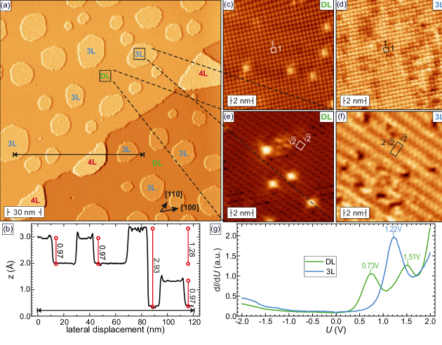
The experimental results of our (SP)-STM experiments are summarized in Fig. 1. All data were taken on a sample which was coated with an average Mn coverage p-AL. The 200 nm nm overview scan in Fig. 1(a) reveals smooth terraces which are covered by a Mn double-layer (DL) with numerous roughly circularly shaped Mn triple-layer (3L) islands on top. The typical island diameter amounts from about nm up to nm. The line section plotted in Fig. 1(b) measured between the two black arrows in Fig. 1(a) shows an apparent height of pm at the tunneling parameters chosen here, i.e., a sample bias voltage and a tunneling current . Moreover, semi-elliptical islands of the fourth Mn layer (4L) with diameters between nm (perpendicular to the step edge) and nm (along the step edge) and a height pm can be found at step edges.
Atomic-resolution measurements performed with a non-magnetic W tip on the flat terrace (covered by a Mn DL) and 3L Mn islands are presented in Fig. 1(c) and (d), respectively. As indicated by white and black boxes, both data sets exhibit a square-shaped unit cell with a lattice constant consistent with the underlying W(001) substrate, pm. Magnetically sensitive SP-STM data acquired on surface areas covered by Mn DL or 3L [indicated in Fig. 1(a)] are shown in Fig. 1(e) and (f), respectively. For the former, we recognize a unit cell which is rotated by with respect to the direction of the W(001) substrate. The contrast is dominated by holes (depressions) surrounded by a grid of linear elevations. As discussed in detail in Ref. 4, this mesh-like appearance in STM images is characteristic for the out-of-plane antiferromagnetic Mn DL on W(001).
Fig. 1(f) presents typical atomic-resolution SP-STM data taken on a 3L Mn island. Zigzag–shaped stripes with an inter-stripe separation of nm and a periodicity of nm along the stripes are observable, corresponding to a magnetic unit cell indicated by a black rectangle. As shown in Fig. 1(g), by recording local tunneling spectra, we detect a very different local electronic structure for DL and 3L Mn. Whereas the DL exhibits peaks at V and V (green curve), the tunneling spectrum of 3L Mn yields only one characteristic peak at V.
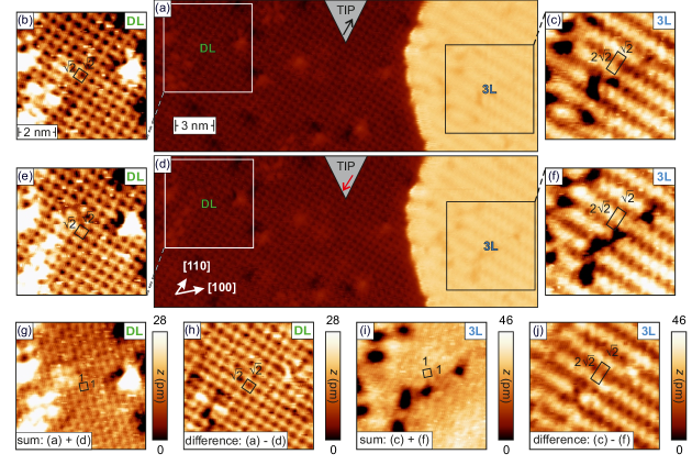
To unambiguously confirm the magnetic origin of the zigzag–shaped contrast observed in Fig. 1(f) we performed experiments in which the same locations covered by DL and 3L Mn on W(001) were imaged by SP-STM before and after reversing the tip magnetization, see Fig. 2. A high-resolution SP-STM scan of a surface area covered by a Mn DL in the darker left part and by a 3L Mn film on the brighter right part is shown in Fig. 2(a). On both surface areas a significant magnetic contrast is obtained, as highlighted in the zoomed-in images presented in Fig. 2(b) and (c), respectively. Since it is known from DFT calculations that the spin structure of the Mn DL on W(001) is out-of-plane antiferromagnetic [4], we can safely conclude that the tip magnetization must exhibit a significant out-of-plane component. Yet, the absolute magnetization direction of the tip is unknown and the scheme in the upper part of Fig. 2(a) serves illustrative purposes only. We also note that we cannot exclude that this out-of-plane magnetization coexists with an in-plane component.
To reverse the magnetization of the out-of-plane component of the tip magnetization, the Mn-W tip was carefully approached by a distance towards the Mn film. To exclude any effect on the previously imaged surface areas, this approach was performed about nm below the region shown in Fig. 2(a). At pm, we suspect that tip and sample orbitals overlap at such close tip–sample distance, resulting in a significant exchange interaction [43, 44, 45, 46, 47] which magnetically reverses the Mn cluster at the tip apex.
Upon this procedure we moved back to the position of Fig. 2(a) and scanned the same surface area with a reversed tip magnetization, see Fig. 2(d). Zoomed-in scans of the Mn DL and 3L are shown in Fig. 2(e) and (f), respectively. Again the characteristic and magnetic unit cells are observable. By using defect sites as markers to precisely aligning the images shown in panels (b) and (e) for the DL, a half-period shift of the magnetic contrast becomes evident. This first impression is corroborated by calculating the sum (g) and the difference (h) of the DL images displayed in (b) and (e). Whereas the sum in Fig. 2(g) exhibits the square-shaped structural unit cell, the difference (h) demonstrates the familiar AFM magnetic unit cell, in agreement with Ref. 4, thereby unambiguously confirming the reversal of the out-of-plane component of the tip magnetization.
Application of the same procedure to the SP-STM data presented in Fig. 2(c) and (f), which were obtained on the 3L region, results in the images presented in Fig. 2(i) for the sum and (j) for the difference. While the sum (i) yields a blurred signal only, possibly due to the very low structural atomic corrugation amplitude of 3L Mn on W(001), the difference image presented in panel (j) clearly reveals the magnetic unit cell, which can also be referred to as the magnetic c unit cell. Please note that the defects are hardly visible in (j) but very pronounced in (i), indicating that the difference image tends to cancel topographic and highlight magnetic contrasts.
IV.2 SP-STM simulations
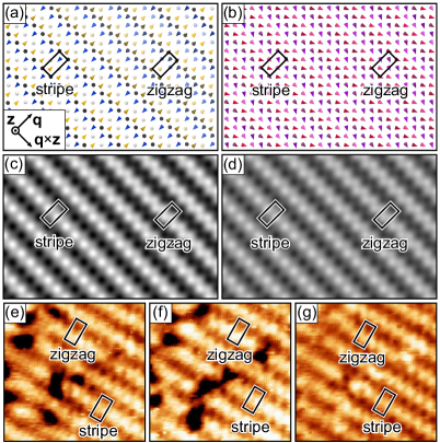
The super cell suggested by the experimental SP-STM images as the magnetic unit cell of the Mn triple layer can be explained by a 90° spin spiral state propagating along the [110] direction of the surface. In such a state the magnetic moments of Mn atoms in adjacent rows perpendicular to the propagation direction are rotated by and the spiral completes a rotation after four lattice sites which exactly matches the super cell. To check whether the experimentally observed contrast can be reproduced by assuming such a spin spiral state, we have simulated SP-STM images (Fig. 3) based on the spin-polarized generalization [48] of the Tersoff-Hamann model [49] using the the model described in Ref. [50]. Note, that in these SP-STM simulations only the magnetic moment directions of the Mn atoms in the surface layer enter, whereas the other two Mn layers have no impact on the simulated images.
For the SP-STM simulations we actually chose an angle of 87.5° between the magnetic moments of Mn atoms in adjacent rows of the top layer (Fig. 3(a)) instead of 90° as this leads to an even better matching of the experimental images. In particular, we observe the formation of different rotational domains (contrasts) on a larger scale while leaving the spin structure locally close to the 90° spiral. The two domains are denoted as stripe and zigzag domains (Fig. 3(a,c)). In the stripe domain the Mn magnetic moments and the magnetization direction of the STM tip enclose angles of 0°, 90° or 180°, while in the other domain a zigzag contrast is found due to enclosing angles of about 45° and 135° (Fig. 3(e)). These two types of contrast also appear in the experimental images (Fig. 3(e-g)).
However, a conical spin spiral with a finite opening angle and an angle of 87.5° between the flat spin spiral component of the magnetic moments of Mn atoms in adjacent rows Fig. 3(b,d) can explain the experimental observations as well. SP-STM simulations reveal that the magnetic contrast only changes in magnitude when going from a flat towards a conical spiral (Fig. 3(c) vs. (d)). The magnetic contrast of conical spirals cannot be distinguished from a flat spin spiral as long as the magnetization direction of the STM tip and the direction of the in-plane component are perpendicular to each other. This is consistent with the experimental situation since the easy magnetization direction of the state obtained in DFT is in the plane of the film (see section IV.3) and the STM tips had an out-of-plane magnetization direction as deduced from the contrast on the Mn double layer.
IV.3 First-principles calculations
| state | method | |||||||||
| FLEUR | 19.5 | 5.5 | 10.9 | 1.0 | 2.3 | 0 | 3.71 | 3.04 | 2.36 | |
| FLEUR | 32.8 | 6.5 | 16.1 | 4.3 | 1.0 | 122 | 3.45 | 2.92 | 1.27 | |
| FLEUR | 7.3 | 23.9 | 2.5 | 1.6 | 3.2 | 35 | 3.75 | 2.37 | 2.39 | |
| AFM | FLEUR | 17.7 | 15.1 | 13.0 | 2.9 | 1.64 | 36 | 3.70 | 2.87 | 0.90 |
| VASP | 24.4 | 4.0 | 15.8 | 0.5 | 0.6 | 0 | 3.67 | 3.13 | 1.90 | |
| VASP | 31.9 | 7.8 | 16.4 | 2.1 | 0.5 | 145 | 3.28 | 2.79 | 1.40 | |
| VASP | 8.3 | 24.7 | 3.8 | 3.4 | 0.9 | 8 | 3.72 | 2.36 | 2.39 | |
| VASP | 27.2 | 9.8 | 15.7 | 1.6 | 0.5 | 90 | 3.47 | 2.90 | 1.35 | |
| Ref. [25] | 0 | 3.78 | 3.14 | 2.39 | ||||||
| Ref. [25] | 0.7 | 97 | 3.71 | 1.34 | 1.43 |
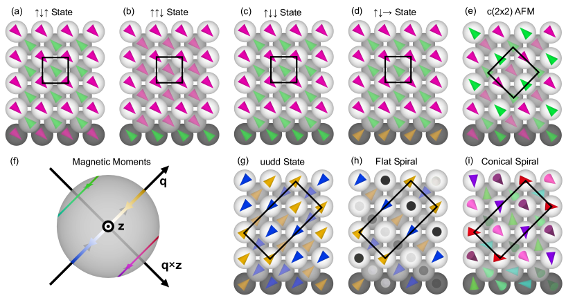
Structural relaxations and collinear states. First we performed DFT calculations for three collinear magnetic states to determine the exchange coupling between the upper and lower two Mn layers (Fig. 4(a-c)). The investigated states were the layerwise antiferromagnetic () state (Fig. 4(a)), and two states in which the magnetic moments of two adjacent Mn layers are parallel and antiparallel with respect to the other Mn layer, i.e. the (Fig. 4(b)) and the state (Fig. 4(c)), where each arrow denotes the magnetization of one Mn layer from top to bottom. Note, that we could not converge the ferromagnetic () state in our DFT calculations as the magnetic moments of the Mn layers flipped such that we arrived at the state.
We carried out structural relaxations for each of the collinear magnetic states using both the FLEUR and the VASP code which give similar results (Tab. 1). Our results show that there is a large inward relaxation of the Mn layers which depends sensitively on the considered magnetic state. For the layerwise antiferromagnetic () state, the relaxations and magnetic moments are in good agreement with those of a previous DFT study on the Mn triple layer on W(001) by Dennler et al. [25], as shown in Tab. 1. Note, that only the ferromagnetic and the state have been considered in that work [25].
Surprisingly, the state (Fig. 4(c)) is energetically much more favorable than the state in both the FLEUR and the VASP calculation (Tab. 1). This indicates antiferromagnetic coupling between magnetic moments of the two upper Mn layers and ferromagnetic coupling between the Mn moments of the central and bottom layer. The magnetic moment of the interfacial (bottom) Mn layer is much smaller than that of the other two Mn layers. The magnetic moment of the bottom Mn layer vanishes if the moment direction is constrained within the FLEUR calculations to be perpendicular to the magnetic moments of the two upper layers (Fig. 4(d)). This indicates that the Mn atoms at the W interface obtain their magnetic moment in this state due to spin-polarization by the two upper Mn layers.
We also observe a strong coupling of magnetic and geometric structure, with a tight binding for antiferromagnetic coupling between the two upper layers and a larger interlayer distance for a ferromagnetic alignment. Note, that the strong inward relaxation of the top Mn layer in the state is consistent with the small apparent height difference between the Mn DL and 3L (cf. Fig. 1).
Our result for the Mn triple layer is consistent with a DFT study for the Mn double layer on W(001) which also indicated a preferred ferromagnetic coupling between adjacent layers [4]. Due to the antiferromagnetic state in the surface Mn layer of the double layer, the magnetic moment of the interfacial Mn layer is quenched in Mn-DL/W(001), indicating that it is also only induced by the adjacent Mn layer [4]. The antiferromagnetic coupling between magnetic moments of the upper Mn layers is also consistent with the DFT calculations of Dennler et al. [25]. The same type of coupling occurs in -Mn due to the weakened influence of the W substrate.
Spin spiral calculations. We have shown that the magnetic contrasts observed in the SP-STM images can be explained by a spin spiral state with an angle of about (Fig. 3). Therefore, we have performed DFT total energy calculations for spin spiral states. Spin spirals are spatially rotating magnetic structures characterized by a spiral vector in reciprocal space (see Fig. 4(f) and (h)). The magnetic moment at site at the position is given by
| (1) |
where is the magnitude of the magnetic moment in layer (see Tab. 1). Eq. (1) describes a cycloidal spin spiral that rotates in the -plane.
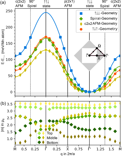
High-symmetry points of the two-dimensional Brillouin zone (2D BZ, inset of Fig. 5(a)) correspond to collinear magnetic states. At the -point, we find the state (Fig. 4(b)), at the -point, the state (Fig. 4(c)), at the -point the c AFM state (Fig. 4(e)) and at the -point the p AFM state. For a spin spiral vector half-way along the high-symmetry direction one obtains a spin spiral with angles of between adjacent Mn moments within a layer (Fig. 4(h)) which could explain the SP-STM measurements. Note, that the orientation of the plane in which the spins rotate is not fixed as long as spin-orbit coupling is neglected.
Starting from the energetically preferred state at the point of the 2D BZ, q was varied for a spiral propagating in all Mn layers which results in the energy dispersion shown in Fig. 5(a). In order to check the influence of the structure of the Mn triple layer, spin spiral calculations were performed for four different geometries corresponding to the relaxed structure of the -state, the spin spiral along , a c() antiferromagnetic state in all magnetic layers and the -state (cf. Table 1). Interlayer distances for all geometries were taken from the FLEUR calculations, except for the spin spiral geometry, which was taken from the VASP calculation.
The energy minimum of lies for all geometries at the ’-point, i.e. at the state (Fig. 5(a)). The spin spiral energy increases as q is varied along the and direction of the two-dimensional Brillouin zone and reaches its maximum at the -point of the first Brillouin zone, i.e. at the state. However, the curvature of in the vicinity of ’ depends significantly on the structural relaxation, i.e. the Mn interlayer distances. The 90° flat spin spiral at which can explain the SP-STM images (Fig. 3) is not favored in our DFT calculations neglecting spin-orbit coupling over the state in any of the investigated geometries. In its own ground state geometry its energy is 25 meV/Mn-atom higher than the state (Fig. 5(a)). For the structure of the c AFM state, the energy of the spin spiral state is only by 10 meV/Mn atom above the state.
| geometry | |||||||||
|---|---|---|---|---|---|---|---|---|---|
| 7.85 | 0.40 | 0.58 | 0.09 | 0.09 | 0.04 | 0.03 | 0.03 | 0.02 | |
| 5.50 | 0.65 | 0.65 | 0.17 | 0.07 | 0.02 | 0.04 | 0.06 | 0.02 | |
| 5.13 | 0.05 | 0.81 | 0.05 | 0.05 | 0.14 | 0.04 | 0.01 | 0.01 | |
| AFM | 4.39 | 0.66 | 0.44 | 0.26 | 0.01 | 0.03 | 0.05 | 0.08 | 0.02 |
The energy dispersion calculated via DFT for spin spirals neglecting spin-orbit coupling (Fig. 5(a)) can be used to parameterize an effective atomistic spin model including only Heisenberg exchange interactions. For simplicity, the triple layer is modeled as a single magnetic layer with one type of magnetic atoms. The spins in the model are placed in a plane at the -coordinates of the Mn atoms in the trilayer. Thereby, the top and bottom layer Mn atoms are mapped to a single site, while the middle layer represents another site of the effective square spin model with a nearest-neighbor distance of . Since there is only one species of atoms in the effective spin model, interactions of atoms that have the same distance within the -plane, i.e. Mn atoms from the top and bottom layer, will be added together. The predictions of the effective model for each energy dispersion are displayed as the continuous colored lines in Fig. 5(a). The parameters of the effective model are listed in Tab. 2.
The exchange interaction between nearest neighbors is the dominating interaction in the spin model of the film ranging from a maximum antiferromagnetic strength of meV for the -ground state geometry to a minimal strength of meV for the c AFM ground state geometry. This interaction is the sum of the interactions between nearest neighbors in the top with middle and middle with bottom layers in the trilayer, making it an interlayer interaction. This result is consistent with the above investigation of interlayer coupling based on collinear magnetic states (cf. Table 1), in which the antiferromagnetic coupling between top and middle layer dominates the ferromagnetic coupling between the bottom two layers. The most preferable magnetic state for a negative is a antiferromagnetic state in the effective spin model, which translates to a triple layer with ferromagnetically aligned layers that have an antiferromagnetic coupling between the layers consistent with the state. The next-nearest exchange interaction, , also prefers an antiferromagnetic coupling (). It represents the nearest-neighbor intralayer interaction, and the next-nearest neighbor interaction between the top and bottom Mn layers. competes with , since the ferromagnetic state in each layer that is stabilized by is energetically the least optimal state for a negative . For a larger ratio , a spin spiral ground state is expected for the atomistic spin model. The same holds for , which is similar to in sign and strength. Exchange constants beyond are quite small in comparison to and have negligible influence of the magnetic ground state of the spin model, leading to checkerboard antiferromagnetic pattern that represents the in the real system. For the c AFM ground state geometry, the competing contributions of interlayer and intralayer exchange to the energy dispersion can be seen in Fig. 6(a). In Fig. 6(a) it is apparent that the two types of exchange interactions compete as the intralayer exchange prefers a spin spiral state, while the interlayer exchange favors the collinear state.
The 90° spin spiral can be used to create another state that is also consistent with the magnetic unit cell suggested by the SP-STM measurements: a superposition of two 90° spin spirals with opposite rotational sense leading to the state [51] (see Fig. 4(g)). This state has recently been observed in hexagonal magnetic monolayers on surfaces [10, 52]. On a bcc (001) surface, it exhibits a magnetic unit cell. It is degenerate in energy with the 90° spin spiral within the Heisenberg model of pair-wise exchange. Total energy differences obtained by DFT calculations must stem from higher-order interactions [51, 10, 53]. We calculated the total energies of an state and a 90° spin spiral with the VASP code in a supercell using the relaxed geometry of the -state. The obtained energies of 37 meV/Mn-atom for the 90° spiral with respect to the state, which is consistent with the FLEUR result, and 60 meV/Mn-atom for the state with respect to the state show that higher-order interactions favor the 90° spin spiral over the state. Note, that the state differs from the spin spiral state in that its SP-STM image only shows a zigzag pattern and cannot explain the observed stripe contrast (cf. Fig. 3).
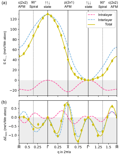
Dzyaloshinskii-Moriya interaction. Since the DMI is known to favor spin spirals over the ferromagnetic state, we investigated if the inclusion of SOC could lead to a non-collinear ground state in the Mn trilayer. The contributions of SOC to the total energies of spin spirals were calculated using FLEUR within first order perturbation theory, starting from self-consistent cycloidal spin spiral states in the AFM ground state geometry (see Fig. 6(b)). Negative energy values decrease the energy of counter-clockwise rotating spirals and positive values decrease the energy of clockwise rotating ones.
Energy contributions at the -point indicate the presence of interlayer DMI, since each layer exhibits a row-wise antiferromagnetic state at this high-symmetry point, i.e. a collinear state without intralayer DMI contributions. By mapping the energies to an effective monolayer system, as for the exchange interaction, it can be revealed that the interlayer DMI is the dominating term. Both interlayer and intralayer DMI favor spin spiral states with an energy minimum along the direction. Along the direction the energy minimum is close to the spin spiral. However, SOC contributions are two orders of magnitude smaller than the total energy of flat spin spirals without SOC.
Magnetic anisotropy. We obtained only a very small magnetocrystalline anisotropy energy of 0.01 meV/Mn atom for the state of the Mn triple layer on W(001) favoring an in-plane orientation of the magnetization. We attribute the small SOC effect to the fact that the bottom Mn layer at the interface to the W substrate exhibits only a small magnetic moment which is induced by the adjacent central Mn layer. Therefore, the Mn layers with significant intrinsic magnetic moments are at a relatively large distance from the heavy W substrate needed to create large SOC effects.
To compute the influence of the magnetic dipole-dipole interactions we numerically summed over the magnetic fields of atomic magnetic moments with a distance of up to 1000 in-plane lattice constants taking the geometrical structure and the magnetic moments of the three different Mn layers obtained from DFT for the state into account. From these calculations we found that the magnetostatic dipolar interaction favors an in-plane orientation of the magnetic moments in the state by 0.036 meV/Mn atom with respect to an out-of-plane orientation. This small value can be understood from the net magnetic moment of the Mn triple layer which amounts to only about 0.75 per unit cell (cf. Table 1). The inclusion of SOC does not change the ground state of the system. DMI alone would prefer a spin spiral with a period of about 200 lattice constants by 4 eV close to the -state. However, the magnetocrystalline anisotropy raises the energy of all cycloidal spin spiral states by 6 eV, thus stabilizing the collinear ground state.
Conical spin spiral states. We can obtain spin spiral states of lower energy than the flat spin spiral by superimposing it with the -state at each lattice site , thereby constructing a conical spin spiral states with magnetic moments
| (2) |
which is characterized by the opening angle that its moments and the rotational axis enclose (Fig. 4(i)). The total energy of a conical spin spiral can be described within the extended Heisenberg model by
| (3) |
in which a biquadratic exchange term has been included as a higher-order interaction to the bilinear exchange. By computing the energy of the conical spin spiral from Eq. (2), the energy
| (4) |
of a spiral with the vector as a function of the opening angle can be derived. For small the energy comes close to the energy of the state. The first and second term arise from bilinear and biquadratic exchange, respectively. The addition of higher-order exchange interactions such as the biquadratic term can lead to an energy minimum for a conical spin spiral as reported for a Mn DL on W(110) [9].
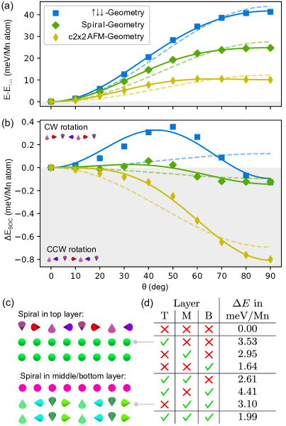
For the 90° spin spiral near the -point, was calculated via DFT for three different ground state geometries (Fig. 7(a)). The obtained total DFT energies closely follow a dependence, indicating large contributions from bilinear exchange, i.e. the first term on the right hand side of Eq. (4). Higher-order exchange contributions significantly improve the fit of the DFT data (Fig. 7(a)). However, they are comparatively small and tend to favor flat spin spirals.
To investigate the influence of SOC, we have calculated the energy contribution due to SOC on the energy of conical spin spirals in the same computational setup using first-order perturbation theory via the FLEUR code. To model the effect of SOC on the energy within the atomistic spin model we used
| (5) |
which contains the DMI as well as the chiral biquadratic pair-interaction that was recently proposed in Ref. [54]. The two vectors and are assumed to align perpendicular to the plane of rotation of the spiral. For the conical spin spiral, Eq. (2), the SOC energy
| (6) |
has the same dependence on as the exchange energy. The second term arises because of the chiral biquadratic pair interaction.
The energy contribution calculated via DFT (Fig. 7(b)) depends strongly on the geometry of the film system, i.e. the Mn interlayer distances. For the AFM ground state geometry, the highest SOC contribution is computed for the flat spin spiral () with about 0.8 meV/Mn atom, preferring an counter-clockwise rotation. The fit of the DFT data to Eq. (6) shows that the chiral biquadratic term plays a non-negligible role (Fig. 7(b)). For the other two considered ground state geometries, the SOC energy for the flat spin spiral () decreases drastically to only 0.1 meV/Mn atom. However, for an opening angle of about to we observe a change of the preferred rotational sense which cannot be explained by the DMI. This unexpected dependence of the SOC energy for conical spin spirals as a function of the opening angle stems from higher-order interactions due to SOC such as the chiral biquadratic term. Especially, for the ground state geometry there is a significant energy gain of about 0.4 meV/Mn atom for a clockwise rotating conical spin spiral with an opening angle of . Nevertheless, the SOC contributions are at least one order of magnitude smaller, even in the AFM ground state geometry. Therefore, within our DFT calculations SOC does not lead to a 90° conical spin spiral that would explain the experimental results.
We have also investigated whether the energy of the conical 90° spin spiral with an opening angle of can be lowered by propagating it only in one or two of the Mn layers, while the other layers are in a ferromagnetic state (sketch in Fig. 7(c)). The results of these calculations are collected in Fig. 7(d). All total energies are given with respect to the state and have been obtained neglecting SOC. While the creation of a spin spiral in one magnetic layer requires energy, less energy is needed for the creation of a second spiral. If both spin spirals propagate in the two top layers, it even lowers the energy with respect to the case of only one spin spiral. This can be explained by the strong antiferromagnetic coupling between the top two layers. The state with spin spirals in all three Mn layers possesses the lowest energy. Such a conical 90° spin spiral with an opening angle of is only about 2 meV/Mn atom higher than the state. Note, that the energy differences of conical spin spirals with respect to the state are expected to be even lower if the calculations were performed for a different structural relaxation similar to the result obtained for flat spin spirals (cf. Fig. 7(a)).
V Conclusion
In our SP-STM experiments, we found the well-known mesh-like structure on the Mn DL on W(001), which was first described in Ref. [4]. This result is in perfect agreement with the c() AFM order in the surface Mn layer and quenched magnetic Mn moments at the Mn/W interface reported by Meyer et al. [4]. Our SP-STM data of pseudomorphic 3L Mn/W(001) films show periodic zigzag patterned stripes consistent with a magnetic unit cell. The magnetic origin of this pattern was verified by experiments, where the tip magnetization was reversed at close tip–sample distance via the exchange interaction, resulting in a characteristic contrast inversion for both DL and 3L Mn, see Fig. 2. A limitation of these spin-polarized measurements lies in the uncertainty of the magnetization direction of the spin-polarized Mn/W tip, namely whether it is entirely out-of-plane magnetized or also includes a significant in-plane component.
SP-STM simulations revealed that a spin spiral state with an angle close to can explain the observed magnetic contrast. A flat spin spiral as well as a conical spin spiral with a finite opening angle is consistent with the SP-STM experiments since the magnetization direction of the tip could not be fully determined.
DFT calculations have been performed using the FLEUR as well as the VASP code to shed light on the magnetic ground state and its origin. Our calculations show that the geometric structure of the Mn triple layer and its magnetic state are closely linked. In particular, the interlayer distances between the Mn layers and to the W substrate change considerably upon changing the magnetic state in the triple-layer.
We found a novel collinear magnetic state for the Mn triple-layer on W(001) which is energetically much more favorable in DFT than the layered antiferromagnetic state previously proposed by Dennler et al. [25]. In this so-called state the magnetic moments of the Mn surface and central layers are oppositely aligned with respect to each other. The magnetic moments of the Mn atoms in the interface layer to the W substrate are aligned parallel to those of the central layer and only induced by the central Mn layer.
Spin spiral calculations performed starting from the state show a total DFT energy rise upon canting the spins, i.e. deviating from the collinear state. Therefore, a flat spin spiral state is unfavorable with respect to the state. However, the energy difference depends significantly on the interlayer distances in the Mn triple-layer. We find that the interlayer exchange prefers the collinear state, while intralayer exchange interactions favor a spin spiral state. The DMI prefers a cycloidal spin spiral state, however, its energy contribution is much smaller than that of the exchange. The magnetocrystalline anisotropy energy is also small in the state and favors an in-plane magnetization. We attribute the small size of the SOC effects to the small Mn moments at the W interface in the state.
DFT calculations for conical spin spiral states show that the energy still rises upon deviating from the collinear state, however, the energy difference is much reduced. Based on these results, we can exclude a significant effect of higher-order exchange interactions in the Mn triple-layer which could be responsible for a conical spin spiral as found for a Mn DL on W(110) [9]. Surprisingly, we found that the energy contribution due to SOC for conical spin spirals deviates qualitatively from that expected by the DMI. Therefore, higher-order interactions due to SOC such as the chiral biquadratic pair interaction need to be taken into account. Such interactions might explain the occurrence of a conical spin spiral state in the Mn triple-layer since the energy difference between a conical spin spiral state with a small opening angle of – which can explain the observed SP-STM images – is only slightly higher in energy than the state. Different opening angles of the conical spin spiral state in the three Mn layers not considered in our DFT calculations might also further lower its total energy.
Acknowledgements.
We would like to thank S. Meyer for fruitful discussions and S. Haldar for technical support with the VASP calculations. We acknowledge support by DFG through Würzburg-Dresden Cluster of Excellence (ct.qmat). T. D. and S. H. gratefully acknowledge financial support from the Deutsche Forschungsgemeinschaft (DFG, German Research Foundation) via the SPP2137 ”Skyrmionics” (project no. 462602351) and computing time provided by the North-German Supercomputing Alliance (HLRN).References
- Blügel et al. [1988] S. Blügel, M. Weinert, and P. H. Dederichs, Ferromagnetism and antiferromagnetism of 3d-metal overlayers on metals, Phys. Rev. Lett. 60, 1077 (1988).
- Heinze et al. [2000] S. Heinze, M. Bode, A. Kubetzka, O. Pietzsch, X. Nie, S. Blügel, and R. Wiesendanger, Real-space imaging of two-dimensional antiferromagnetism on the atomic scale, Science 288, 1805 (2000).
- Kubetzka et al. [2005] A. Kubetzka, P. Ferriani, M. Bode, S. Heinze, G. Bihlmayer, K. von Bergmann, O. Pietzsch, S. Blügel, and R. Wiesendanger, Revealing Antiferromagnetic Order of the Fe Monolayer on W(001): Spin-Polarized Scanning Tunneling Microscopy and First-Principles Calculations, Phys. Rev. Lett. 94, 087204 (2005).
- Meyer et al. [2020] S. Meyer, M. Schmitt, M. Vogt, M. Bode, and S. Heinze, Dead magnetic layers at the interface: Moment quenching through hybridization and frustration, Phys. Rev. Research 2, 012075(R) (2020).
- Gao et al. [2008] C. L. Gao, W. Wulfhekel, and J. Kirschner, Revealing the 120° Antiferromagnetic Néel Structure in Real Space: One Monolayer Mn on Ag(111), Phys. Rev. Lett. 101, 267205 (2008).
- Waśniowska et al. [2010] M. Waśniowska, S. Schröder, P. Ferriani, and S. Heinze, Real space observation of spin frustration in cr on a triangular lattice, Phys. Rev. B 82, 012402 (2010).
- Bode et al. [2007a] M. Bode, M. Heide, K. von Bergmann, P. Ferriani, S. Heinze, G. Bihlmayer, A. Kubetzka, O. Pietzsch, S. Blügel, and R. Wiesendanger, Chiral magnetic order at surfaces driven by inversion asymmetry, Nature 447, 190 (2007a).
- Ferriani et al. [2008] P. Ferriani, K. von Bergmann, E. Y. Vedmedenko, S. Heinze, M. Bode, M. Heide, G. Bihlmayer, S. Blügel, and R. Wiesendanger, Atomic-Scale Spin Spiral with a Unique Rotational Sense: Mn Monolayer on W(001), Phys. Rev. Lett. 101, 027201 (2008).
- Yoshida et al. [2012] Y. Yoshida, S. Schröder, P. Ferriani, D. Serrate, A. Kubetzka, K. von Bergmann, S. Heinze, and R. Wiesendanger, Conical Spin-Spiral State in an Ultrathin Film Driven by Higher-Order Spin Interactions, Phys. Rev. Lett. 108, 087205 (2012).
- Krönlein et al. [2018] A. Krönlein, M. Schmitt, M. Hoffmann, J. Kemmer, N. Seubert, M. Vogt, J. Küspert, M. Böhme, B. Alonazi, J. Kügel, H. A. Albrithen, M. Bode, G. Bihlmayer, and S. Blügel, Magnetic Ground State Stabilized by Three-Site Interactions: , Phys. Rev. Lett. 120, 207202 (2018).
- Spethmann et al. [2020] J. Spethmann, S. Meyer, K. von Bergmann, R. Wiesendanger, S. Heinze, and A. Kubetzka, Discovery of Magnetic Single- and Triple- States in Mn/Re(0001), Phys. Rev. Lett. 124, 227203 (2020).
- Gutzeit et al. [2022] M. Gutzeit, A. Kubetzka, S. Haldar, H. Pralow, M. Goerzen, R. Wiesendanger, S. Heinze, and K. von Bergmann, Nano-scale collinear multi-q states driven by higher-order interactions, Nat. Commun. 13, 5764 (2022).
- Pietzsch et al. [2001] O. Pietzsch, A. Kubetzka, M. Bode, and R. Wiesendanger, Observation of magnetic hysteresis at the nanometer scale by spin-polarized scanning tunneling spectroscopy, Science 292, 2053 (2001).
- Meckler et al. [2009] S. Meckler, N. Mikuszeit, A. Preßler, E. Y. Vedmedenko, O. Pietzsch, and R. Wiesendanger, Real-space observation of a right-rotating inhomogeneous cycloidal spin spiral by spin-polarized scanning tunneling microscopy in a triple axes vector magnet, Phys. Rev. Lett. 103, 157201 (2009).
- Perini et al. [2019] M. Perini, S. Meyer, A. Kubetzka, R. Wiesendanger, S. Heinze, and K. von Bergmann, Electrical detection of domain walls and skyrmions in co films using noncollinear magnetoresistance, Phys. Rev. Lett. 123, 237205 (2019).
- Heinze et al. [2011] S. Heinze, K. von Bergmann, M. Menzel, J. Brede, A. Kubetzka, R. Wiesendanger, G. Bihlmayer, and S. Blügel, Spontaneous atomic-scale magnetic skyrmion lattice in two dimensions, Nat. Phys. 7, 713 (2011).
- Romming et al. [2013] N. Romming, C. Hanneken, M. Menzel, J. E. Bickel, B. Wolter, K. von Bergmann, A. Kubetzka, and R. Wiesendanger, Writing and deleting single magnetic skyrmions, Science 341, 636 (2013).
- Hervé et al. [2018] M. Hervé, B. Dupé, R. Lopes, M. Böttcher, M. D. Martins, T. Balashov, L. Gerhard, J. Sinova, and W. Wulfhekel, Stabilizing spin spirals and isolated skyrmions at low magnetic field exploiting vanishing magnetic anisotropy, Nat. Commun. 9, 1015 (2018).
- Meyer et al. [2019] S. Meyer, M. Perini, S. von Malottki, A. Kubetzka, R. Wiesendanger, K. von Bergmann, and S. Heinze, Isolated zero field sub-10 nm skyrmions in ultrathin Co films, Nat. Commun. 10, 3823 (2019).
- Finco et al. [2016] A. Finco, P.-J. Hsu, A. Kubetzka, K. von Bergmann, and R. Wiesendanger, Tailoring noncollinear magnetism by misfit dislocation lines, Phys. Rev. B 94, 214402 (2016).
- Finco et al. [2017] A. Finco, L. Rózsa, P.-J. Hsu, A. Kubetzka, E. Vedmedenko, K. von Bergmann, and R. Wiesendanger, Temperature-induced increase of spin spiral periods, Phys. Rev. Lett. 119, 037202 (2017).
- Hauptmann et al. [2018] N. Hauptmann, M. Dupé, T.-C. Hung, A. K. Lemmens, D. Wegner, B. Dupé, and A. A. Khajetoorians, Revealing the correlation between real-space structure and chiral magnetic order at the atomic scale, Phys. Rev. B 97, 100401 (2018).
- Dupé et al. [2018] M. Dupé, S. Heinze, J. Sinova, and B. Dupé, Stability and magnetic properties of Fe double layers on Ir(111), Phys. Rev. B 98, 224415 (2018).
- Ferriani et al. [2005] P. Ferriani, S. Heinze, G. Bihlmayer, and S. Blügel, Unexpected trend of magnetic order of 3d transition-metal monolayers on W(001), Phys. Rev. B 72, 024452 (2005).
- Dennler and Hafner [2005a] S. Dennler and J. Hafner, First-principles study of ultrathin magnetic Mn films on W surfaces. I. Structure and magnetism, Phys. Rev. B 72, 214413 (2005a).
- Dennler and Hafner [2005b] S. Dennler and J. Hafner, First-principles study of ultrathin magnetic Mn films on W surfaces. II. Surface diffusion, Phys. Rev. B 72, 214414 (2005b).
- Ondráček et al. [2007] M. Ondráček, J. Kudrnovský, I. Turek, and F. Máca, Magnetism of 3d transition metal atoms on W(001): submonolayer films, J. Phys.: Conf. Ser. 61, 894 (2007).
- Tian and Jona [2001] Y. Tian and F. Jona, Nanoscale films of -Mn on W(001), J. Phys.: Condens. Matter 13, 1805 (2001).
- Bode et al. [2007b] M. Bode, S. Krause, L. Berbil-Bautista, S. Heinze, and R. Wiesendanger, On the preparation and electronic properties of clean W(110) surfaces, Surface Science 601, 3308 (2007b).
- Loth et al. [2010] S. Loth, K. von Bergmann, M. Ternes, A. F. Otte, C. P. Lutz, and A. J. Heinrich, Controlling the state of quantum spins with electric currents, Nature Physics 6, 340 (2010).
- Horcas et al. [2007] I. Horcas, R. Fernández, and J. M. Gómez-Rodríguez, WSXM: A software for scanning probe microscopy and a tool for nanotechnology, Rev. Sci. Instrum. 78, 013705 (2007).
- [32] See https://www.flapw.de.
- Kurz et al. [2004] P. Kurz, F. Förster, L. Nordström, G. Bihlmayer, and S. Blügel, Ab initio treatment of noncollinear magnets with the full-potential linearized augmented plane wave method, Phys. Rev. B 69, 024415 (2004).
- Zimmermann et al. [2014] B. Zimmermann, M. Heide, G. Bihlmayer, and S. Blügel, First-principles analysis of a homochiral cycloidal magnetic structure in a monolayer Cr on W(110), Phys. Rev. B 90, 115427 (2014).
- [35] See https://www.vasp.at/.
- Kresse and Furthmüller [1996] G. Kresse and J. Furthmüller, Efficient iterative schemes for ab initio total-energy calculations using a plane-wave basis set, Phys. Rev. B 54, 11169 (1996).
- Kresse and Joubert [1999] G. Kresse and D. Joubert, From ultrasoft pseudopotentials to the projector augmented-wave method, Phys. Rev. B 59, 1758 (1999).
- Perdew and Wang [1992] J. P. Perdew and Y. Wang, Accurate and simple analytic representation of the electron-gas correlation energy, Phys. Rev. B 45, 13244 (1992).
- Vosko et al. [1980] S. H. Vosko, L. Wilk, and M. Nusair, Accurate spin-dependent electron liquid correlation energies for local spin density calculations: a critical analysis, Canadian Journal of Physics 58, 1200 (1980).
- Heide et al. [2009] M. Heide, G. Bihlmayer, and S. Blügel, Describing dzyaloshinskii–moriya spirals from first principles, Physica B: Condensed Matter 404, 2678 (2009).
- Li et al. [1990] C. Li, A. J. Freeman, H. J. F. Jansen, and C. L. Fu, Magnetic anisotropy in low-dimensional ferromagnetic systems: Fe monolayers on ag(001), au(001), and pd(001) substrates, Phys. Rev. B 42, 5433 (1990).
- Perdew et al. [1996] J. P. Perdew, K. Burke, and M. Ernzerhof, Generalized gradient approximation made simple, Phys. Rev. Lett. 77, 3865 (1996).
- Tao et al. [2009] K. Tao, V. S. Stepanyuk, W. Hergert, I. Rungger, S. Sanvito, and P. Bruno, Switching a single spin on metal surfaces by a stm tip: Ab initio studies, Phys Rev Lett 103, 057202 (2009).
- Hsu et al. [2010] P.-J. Hsu, C.-I. Lu, S.-W. Chen, W.-J. Hsueh, Y.-H. Chu, C.-H. Hsu, C. J. Butler, and M.-T. Lin, In situ magnetization switching of magnetic probes applied to spin-polarized scanning tunneling microscopy, Applied Physics Letters 96, 142515 (2010).
- Schmidt et al. [2011] R. Schmidt, C. Lazo, U. Kaiser, A. Schwarz, S. Heinze, and R. Wiesendanger, Quantitative measurement of the magnetic exchange interaction across a vacuum gap, Phys. Rev. Lett. 106, 257202 (2011).
- Schmidt et al. [2012] R. Schmidt, A. Schwarz, and R. Wiesendanger, Magnetization switching utilizing the magnetic exchange interaction, Phys. Rev. B 86, 174402 (2012).
- Hauptmann et al. [2020] N. Hauptmann, S. Haldar, T.-C. Hung, W. Jolie, M. Gutzeit, D. Wegner, S. Heinze, and A. A. Khajetoorians, Quantifying exchange forces of a non-collinear magnetic structure on the atomic scale, Nat. Commun. 11, 1197 (2020).
- Wortmann et al. [2001] D. Wortmann, S. Heinze, P. Kurz, G. Bihlmayer, and S. Blügel, Resolving complex atomic-scale spin structures by spin-polarized scanning tunneling microscopy, Phys. Rev. Lett. 86, 4132 (2001).
- Tersoff and Hamann [1985] J. Tersoff and D. R. Hamann, Theory of the scanning tunneling microscope, Phys. Rev. B 31, 805 (1985).
- Heinze [2006] S. Heinze, Simulation of spin-polarized scanning tunneling microscopy images of nanoscale non-collinear magnetic structures, Appl. Phys. A 85, 407 (2006).
- Hardrat et al. [2009] B. Hardrat, A. Al-Zubi, P. Ferriani, S. Blügel, G. Bihlmayer, and S. Heinze, Complex magnetism of iron monolayers on hexagonal transition metal surfaces from first principles, Phys. Rev. B 79, 094411 (2009).
- Romming et al. [2018] N. Romming, H. Pralow, A. Kubetzka, M. Hoffmann, S. von Malottki, S. Meyer, B. Dupé, R. Wiesendanger, K. von Bergmann, and S. Heinze, Competition of Dzyaloshinskii-Moriya and Higher-Order Exchange Interactions in Atomic Bilayers on Ir(111), Phys. Rev. Lett. 120, 207201 (2018).
- Hoffmann and Blügel [2020] M. Hoffmann and S. Blügel, Systematic derivation of realistic spin models for beyond-Heisenberg solids, Phys. Rev. B 101, 024418 (2020).
- Brinker et al. [2019] S. Brinker, M. dos Santos Dias, and S. Lounis, The chiral biquadratic pair interaction, New Journal of Physics 21, 083015 (2019).