Realization of the unidirectional amplification in a cavity magnonic system
Abstract
We experimentally demonstrate the nonreciprocal microwave amplification using a cavity magnonic system, consisting of a passive cavity (i.e., the split-ring resonator), an active feedback circuit integrated with an amplifier, and a ferromagnetic spin ensemble (i.e., a yttrium-iron-garnet sphere). Combining the amplification provided by the active circuit and the nonreciprocity supported by the cavity magnonics, we implement a nonreciprocal amplifier with the functions of both unidirectional amplification and reverse isolation. The microwave signal is amplified by 11.5 dB in the forward propagating direction and attenuated in the reverse direction by -34.7 dB, giving an isolation ratio of 46.2 dB. Such a unidirectional amplifier can be readily employed in quantum technologies, where the device can simultaneously amplify the weak signal output by the quantum system and isolate the sensitive quantum system from the backscattered external noise. Also, it is promising to explore more functions and applications using a cavity magnonic system with real gain.
Nonreciprocal devices, which exhibit the characteristic of unidirectionality, can play a crucial role in the information technology. To realize the nonreciprocity, various methods have been proposed, such as the magneto-optical Faraday rotation Wolfe et al. (1995); Wang and Fan (2005); Belotelov, Doskolovich, and Zvezdin (2007); Bi et al. (2011); Chin et al. (2013), nonlinearity Christodoulides and Joseph (1988); Shi, Yu, and Fan (2015); Fan et al. (2012); Wang et al. (2012); Huang et al. (2018), spatial-temporal modulation Hwang, Yun, and Kim (1997); Wang et al. (2013); Doerr, Dupuis, and Zhang (2011); Lira et al. (2012), and reservoir engineering Metelmann and Clerk (2015); Fang et al. (2017). The main function of the nonreciprocal devices is to both transmit information in the desired direction and isolate the backscattered noise. The typical feature is that the signal is transmitted in one direction with some insertion loss, and the reverse direction propagation has a large attenuation. On the other hand, in the process of signal transmission, the signal will inevitably attenuate continuously when increasing the propagation distance, so the gain medium and amplification device Xiao et al. (2010); Massel et al. (2011); Fermann et al. (2000); De Leon and Berini (2010); Liu et al. (2007); Khurgin and Sun (2012); Choksi et al. (2022); Stehlik et al. (2016); Frolov et al. (1999); Yao et al. (2017, 2023) are also a critical component in the information technology.
Under normal circumstances, the nonreciprocal and gain devices are independent of each other in the information network, each performing its own function separately. With the increasingly high requirements for integrating signal processing devices, whether both nonreciprocity and signal amplification can be realized in the same device has become an urgent demand. Different systems were proposed to realize the unidirectional amplification, including the atomic system Lin et al. (2019), whispering-gallery microcavities Peng et al. (2014), Josephson circuit Abdo et al. (2013, 2014), microwave optomechanical device Malz et al. (2018); de Lépinay et al. (2019), magnonic system Zhao et al. (2022), and others Koutserimpas and Fleury (2018); Kamal and Metelmann (2017); Jiang et al. (2018); Galiffi, Huidobro, and Pendry (2019); Song et al. (2019); Taravati and Eleftheriades (2021).
Recently, cavity magnonics has emerged as a new research frontier Rameshti et al. (2022). Based on this platform, various applications in, e.g., memory Zhang et al. (2015); Shen et al. (2021), cavity optomagnonics for quantum transduction Osada et al. (2016); Tabuchi et al. (2015); Hisatomi et al. (2016); Haigh et al. (2015, 2016); Zhang et al. (2016); Kusminskiy, Tang, and Marquardt (2016); Graf et al. (2018); Sharma et al. (2019); Wu et al. (2021); Lauk et al. (2020), and magnon sensing at the quantum level Lachance-Quirion et al. (2020); Wolski et al. (2020); Xu et al. (2023a, b) have been reported. In the cavity magnonic system, a magnon mode (i.e., the Kittel mode) in a ferrite, e.g., the yttrium-iron-garnet (YIG) sphere, strongly couples to the microwave photons in the cavity. As a mature commercial material, the YIG owns significant advantages such as the high spin density Huebl et al. (2013); Zhang et al. (2014); Tabuchi et al. (2014), flexible adjustment of resonant frequency Chumak et al. (2015); Wang and Hu (2020), and low damping rate. Very recently, novel properties of the nonreciprocity and unidirectional invisibility have also been observed in the cavity magnonic system Wang et al. (2019), which arise from the interference between the coherent and dissipative magnon-photon interactions. By combining the easy-to-tune ferrite and the specially designed cavities, isolators with both nearly infinite isolation ratios and adjustable working frequencies become implementable Wang et al. (2019); Qian et al. (2020); Zhang et al. (2020); Zhao et al. (2020); Zhang et al. (2021); Kim et al. (2022).
In this work, we construct a nonreciprocal amplifier based on the cavity magnonic system, consisting of a passive cavity made by the split-ring resonator (SRR), an active circuit with an embedded amplifier, and a YIG sphere. These components are all connected to a strip-line waveguide that supports the traveling photon mode. The active circuit is employed to compensate the dissipation of the passive cavity until the signal amplification occurs. The coupling strength between the magnon and cavity modes can be modified by adjusting the position of the YIG sphere with respect to the passive cavity. Through the comprehensive and synergistic regulation of the active circuit and magnon-photon coupling strength, we experimentally realize the microwave nonreciprocal amplification with a high isolation ratio. In the optimal conditions, the device exhibits a rightward propagating amplificition of 11.5 dB and a reverse propagating attenuation of -34.7 dB. Such devices have potential applications in quantum networks and repeaters Reiserer and Rempe (2015); Wehner, Elkouss, and Hanson (2018); Zhong et al. (2021); Nguyen et al. (2019); Li et al. (2021). They may also be promising in protecting the sensitive quantum system from noises associated with the read-out electronics and amplifying the weak signal leaking out of the quantum nodes.
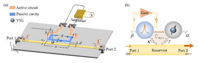
The nonreciprocal amplification device is depicted in Fig. 1(a), where the microwave circuit consists of a strip-line waveguide, a passive cavity made by the split-ring resonator (SRR), and an active circuit with an embedded amplifier. For the passive cavity, a SRR wih parameters mm, mm, mm, and mm is side-coupled to the strip-line waveguide with a distance of mm, and the resonant frequency of the SRR is designed to be GHz to match the optimal working frequency of the active circuit Zarifi, Thundat, and Daneshmand (2015). The active circuit is capacitively coupled to the SRR via a gap of mm. By introducing a gain through the amplifier, the active circuit can compensate the loss of the passive cavity. In the experiment, we apply a DC voltage on the amplifier to continuously adjust the gain provided by the active circuit. The strip-line waveguide has a width of mm for 50 impedance matching. Both the cavity and waveguide are fabricated on a F4B substrate. A 1 mm-diameter YIG sphere is glued at the end of a displacement cantilever, and the relative position between the YIG sphere and the planar microwave circuit can be finely adjusted by a three-dimensional (3D) motor-controlled robot arm. An external magnetic field is applied perpendicularly to the planar device, which is used to both saturate the magnetization of the YIG sphere and tune the frequency of the magnon mode. To characterize this device, a vector network analyzer (VNA) with a signal power of -20 dBm is used to measure the transmission spectrum , where the subscript 21 (12) indicates that the microwave field is loaded to the port 1 (2) and propagates to the port 2 (1) (see Supplementary Material Sec. I).
Our device is schematically shown in Fig. 1(b), where the cavity mode and the magnon mode dissipate cooperatively to the traveling wave-type dissipative reservoir (waveguide). Here, and are the intrinsic damping rates of the magnon mode and the passive cavity mode, respectively, and can be reduced by the active circuit, or even turned to be negative. The external damping rates of the magnon mode and the cavity mode, i.e., and , reflect their interactions with the waveguide traveling photon modes. The cooperative dissipation gives rise to the dissipative coupling between the cavity mode and the magnon mode Metelmann and Clerk (2015); Fang et al. (2017); Wang et al. (2019). Meanwhile, the cavity mode and the magnon mode can directly interact with each other via the spatial mode overlapping, which is attributed to the coherent magnon-photon coupling.
When the coupling mechanism of our system is dominated by both coherent and dissipative couplings, the interference between them has a significant modulation on the transmission spectrum of the system. Due to the asymmetric location of the YIG sphere with respect to the central line of the device, the phase difference between the coherent and dissipative couplings will be different when the microwave is loaded to the ports 1 and 2. Under the circumstances, the overall coupling between the cavity mode and the magnon mode can become direction-dependent. In other words, the nonreciprocity stems from the inconsistent interference effect between the coherent and dissipative couplings when the microwave transmission direction is reversed Wang et al. (2019).
We define to characterize the direction-dependent complex coupling, where denotes the coherent coupling, corresponds to the dissipative coupling, with indicating the non-Hermiticity of the dissipative coupling, and the subscript represents the case when the signal is loaded to the port 1 (2). When the traveling wave propagates in the opposite direction, , so the nonreciprocity emerges. Under the rotating-wave approximation, the Hamiltonian of the non-Hermitian system can be written as
| (1) |
where and are the complex frequencies of the cavity mode and the magnon mode, respectively, while () and () are the creation (annihilation) operators of the cavity mode and the magnon mode, respectively.
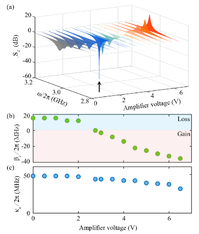
Below we first characterize the loss compensation of the active circuit to the passive cavity, and find out the relationship between the bias voltage of the amplifier and the compensated dissipation of the passive cavity. Figure 2(a) shows the response of the cavity mode to the bias voltage applied on the amplifier, where the measured transmission spectra at a series of bias voltages are plotted. When the voltage is zero, , and the spectrum shows a dip at the resonant frequency of the cavity mode. With the increase of the amplifier voltage, the amplitude of decreases until an ultra-sharp dip (55 dB) appears. Then, it gradually increases and the spectrum turns into a resonance peak with . This process is accompanied with the intrinsic damping rate of the cavity mode compensated to be zero and then negative. The transmission coefficient of the side-coupled cavity mode can be described by the following equation:
| (2) |
where and are the effective external and intrinsic damping rates of the cavity mode, respectively. The parameter indicates that the external damping rate of the cavity mode is affected by the active circuit when the bias voltage is applied. The parameter is introduced as the gain coefficient, which is determined by the amplifier bias voltage and is equal to the linewidth compensation of the cavity mode.
The bare cavity mode (corresponding to zero bias voltage) has an external damping rate of MHz, and an intrinsic damping rate of MHz. By continuously tuning the bias voltage, the fitted and versus the bias voltage are plotted as the green and blue circles in Fig. 2(b) and Fig. 2(c), respectively. When the amplifier voltage is small, the intrinsic dissipation of the cavity mode is not fully compensated (, ). While the amplifier voltage reaches 2.75 V, the intrinsic damping rate of the cavity mode is almost exactly compensated by the active circuit (, ), resulting in an extremely abrupt dip in , as marked by an arrow in Fig. 2(a). With the increase of the amplifier bias voltage, the gain coefficient exceeds the intrinsic damping rate, giving rise to an effective negative intrinsic damping rate of the cavity mode (, ). It is worth noting that the amplifier also affects the external damping rate of the cavity mode, as shown in Fig. 2(c). However, its effect on the microwave transmission is not significant, and the transmitted signal appears as either amplification or attenuation, depending primarily on the compensation of the intrinsic dissipation (see Supplementary Material Sec. II for details). By introducing the active circuit, the transmission amplitude becomes amplified around the cavity mode frequency, and the loss-compensated cavity is a crucial element for the subsequent realization of the nonreciprocal amplification.
With the amplification mechanism in hand, the next step is to construct the nonreciprocity of the system. Additionally, the YIG sphere is attached to the cavity. The magnon mode sustained by the YIG sphere is coherently and dissipatively coupled to the cavity photon mode. The nonreciprocity originates from the interference between the coherent and dissipative couplings, and the phase of the interference term is related to the direction of the microwave propagation, which leads to a direction-dependent complex coupling . The magnon-photon coupling induces hybridized modes with complex frequencies
| (3) |
Using the input-output theory (see Supplementary Material Sec. III for details), we obtain the transmission spectrum of the coupled system as
| (4) |
where the complex coupling strength between the cavity and magnon modes is direction-dependent as stated above, resulting in nonreciprocal transmission spectra, i.e., . It is necessary to adjust the ratio between the coherent and dissipative coupling strengths for an optimal nonreciprocal transmission. Experimentally, we modify the complex coupling strength by fixing the height of the YIG sphere relative to the planar device at a distance of mm and then precisely controlling its position in the x-y plane.
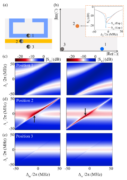
To clearly show the existing region of the nonreciprocal transmission exists and reveal its origin in our device, here we place the YIG sphere at three different positions relative to the cavity, as shown in Fig. 3(a). We depict the corresponding and mappings versus the field detuning and the probe frequency detuning in Figs. 3(c)-(e), respectively. When the YIG sphere is at position 1, the two hybridized modes shown in Fig. 3(c) exhibit level repulsion, a characteristic of coherent magnon-photon coupling Huebl et al. (2013); Zhang et al. (2014); Tabuchi et al. (2014). Using Eq. (3) to fit the experimental results, we find that at position 1 the real part of the complex coupling strength is significantly larger than the imaginary part , as depicted by the blue dot in Fig. 3(b). Nonreciprocity cannot be observed in this instance because the interference term between the coherent and dissipative couplings is negligibly small. As observed in the left () and right panels () of Figure 3(c), transmission mappings are nearly identical.
When the YIG sphere is placed at position 2, the mode hybridization as shown in Fig. 3(d) is quite distinct from level repulsion but similar to level attraction, indicating the coexistence of dissipative and coherent magnon-photon couplings Wang et al. (2019). As indicated by the orange dot in Fig. 3(b), when the YIG sphere is placed at position 2, the coherent and dissipative coupling strengths are comparable. The interference between coherent and dissipative couplings then plays a crucial role. Consequently, the nonreciprocity is evident in Fig. 3(d), where is observed at various detunings. As an illustration, we plot the nonreciprocal transmission at the arrow-marked field detuning in Fig. 3(d). As depicted in the inset of Fig. 3(b), red and blue curves correspond to and , respectively.
The coupling strength tends to be zero [gray dot in Fig. 3(b)] when the YIG sphere is placed at position 3, which is far from the cavity and transmission line. Conceivably, nonreciprocal transmission does not occur in this case either. The measured transmission mappings of and are shown in Fig. 3(e). Through the measurements at the positions above, we can find that the coexistence of coherent and dissipative couplings is very crucial for the emergence of nonreciprocal transmission. In addition, to obtain the maximum nonreciprocal response, the coherent and dissipative coupling strengths should be comparable.
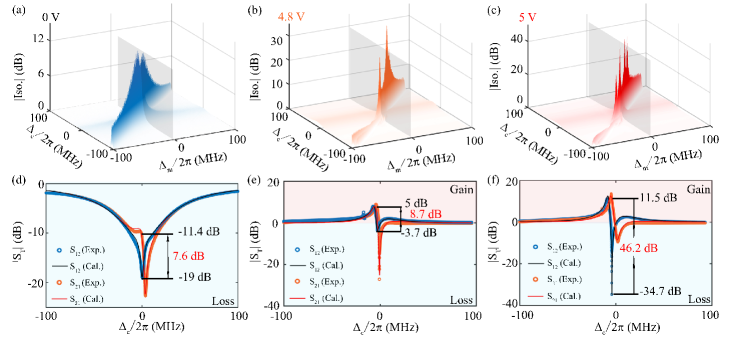
Combining the transmission amplification caused by the dissipation-compensated cavity and the nonreciprocity of the coupled system, we achieve the unidirectional amplification and isolation, as shown in Fig. 4. In order to quantify isolation, the difference between the rightward () and leftward () transmission amplitudes is extracted and plotted as . Here we use its absolute value as the isolation ratio (Iso.) of the system. The experimentally observed isolation ratios at different amplifier bias voltages (=0, 4.8, 5 V) are plotted versus and in Figs. 4(a)-(c). As the bias voltage of the amplifier rises, the intrinsic damping rate of the hybrid system transits from the positive to negative, which means the generation of a net gain in the system (see Supplementary Material Sec. IV). The maximum isolation ratio increases as more signal gain is supplied to the system. On the premise of a high level of isolation, it is crucial to find out the optimal operating point in order to achieve a relatively large unidirectional signal amplification. We choose the field detuning position marked by the gray planes in Figs. 4(a)-(c) as examples, and plot the and spectra in Figs. 4(d)-(f), respectively. The circle points are the experimental results, while the solid curves are the theoretical results obtained using Eq. (4), which are in good agreement. The microwave transmission depicted in Fig. 4(d) is nonreciprocal without amplification, because the bias voltage of the amplifier is set to zero. In Figs. 4(e) and 4(f), the unidirectional amplification is realized when bias voltage is applied to the amplifier. At the working frequency of GHz, the rightward propagating microwave can be amplified by 11.5 dB, whereas the leftward propagating microwave can be attenuated by 34.7 dB, giving an isolation ratio of 46.2 dB. Fitting these spectra with Eq. (4), we obtain the propagation direction-dependent complex coupling strengths of the system, which are MHz and MHz.
In conclusion, we have designed a novel nonreciprocal device that performs unidirectional amplification and reserve isolation simultaneously. The device consists of an active circuit with an embedded amplifier, a passive cavity made by SRR, and a YIG sphere. The unidirectional amplification of the microwave signal is accomplished by combining the nonreciprocity of the cavity magnonic system with the conventional active feedback of the gain medium. By adjusting the bias voltage of the amplifier in the active feedback circuit, we can compensate for loss of the passive cavity mode and convert it to a gain regime. Meanwhile, the coupling strength between the cavity photon mode and the magnon mode is controlled by the relative position between the device and the YIG sphere. By balancing the coherent and dissipative couplings, the interference between them can result in nonreciprocity in our system. By optimization via amplifier bias voltage and photon-magnon coupling strength, we are able to achieve microwave transmission amplification of 11.5 dB in one propagation direction and attenuation of 34.7 dB in the opposite propagation direction. Such a unidirectional amplification device may have promising applications in quantum information technologies, as it can both amplify the weak signal leaking from the principal quantum system and isolate the back-scattered noise from the readout electronics. This design of integrating two functions in just one device will provide advantages for the construction of large-scale information networks.
Acknowledgements.
We thank Zi-Qi Wang for helpful discussion. This work is supported by the National Key Research and Development Program of China (Grant No. 2022YFA1405200), the National Natural Science Foundation of China (Grants No. 92265202, No. 11934010, and No. 12174329), the Fundamental Research Funds for the Central Universities (Grant No. 2021FZZX001-02).Data Availability Statement
The data that support the findings of this study are available from the corresponding author upon reasonable request.
References
- Wolfe et al. (1995) R. Wolfe, W.-K. Wang, D. DiGiovanni, and A. Vengsarkar, “All-fiber magneto-optic isolator based on the nonreciprocal phase shift in asymmetric fiber,” Optics letters 20, 1740–1742 (1995).
- Wang and Fan (2005) Z. Wang and S. Fan, “Optical circulators in two-dimensional magneto-optical photonic crystals,” Optics letters 30, 1989–1991 (2005).
- Belotelov, Doskolovich, and Zvezdin (2007) V. Belotelov, L. Doskolovich, and A. Zvezdin, “Extraordinary magneto-optical effects and transmission through metal-dielectric plasmonic systems,” Physical review letters 98, 077401 (2007).
- Bi et al. (2011) L. Bi, J. Hu, P. Jiang, D. H. Kim, G. F. Dionne, L. C. Kimerling, and C. Ross, “On-chip optical isolation in monolithically integrated non-reciprocal optical resonators,” Nature Photonics 5, 758–762 (2011).
- Chin et al. (2013) J. Y. Chin, T. Steinle, T. Wehlus, D. Dregely, T. Weiss, V. I. Belotelov, B. Stritzker, and H. Giessen, “Nonreciprocal plasmonics enables giant enhancement of thin-film faraday rotation,” Nature communications 4, 1599 (2013).
- Christodoulides and Joseph (1988) D. Christodoulides and R. Joseph, “Discrete self-focusing in nonlinear arrays of coupled waveguides,” Optics letters 13, 794–796 (1988).
- Shi, Yu, and Fan (2015) Y. Shi, Z. Yu, and S. Fan, “Limitations of nonlinear optical isolators due to dynamic reciprocity,” Nature photonics 9, 388–392 (2015).
- Fan et al. (2012) L. Fan, J. Wang, L. T. Varghese, H. Shen, B. Niu, Y. Xuan, A. M. Weiner, and M. Qi, “An all-silicon passive optical diode,” Science 335, 447–450 (2012).
- Wang et al. (2012) J. Wang, L. Fan, L. T. Varghese, H. Shen, Y. Xuan, B. Niu, and M. Qi, “A theoretical model for an optical diode built with nonlinear silicon microrings,” Journal of Lightwave Technology 31, 313–321 (2012).
- Huang et al. (2018) R. Huang, A. Miranowicz, J.-Q. Liao, F. Nori, and H. Jing, “Nonreciprocal photon blockade,” Physical review letters 121, 153601 (2018).
- Hwang, Yun, and Kim (1997) I. K. Hwang, S. H. Yun, and B. Y. Kim, “All-fiber-optic nonreciprocal modulator,” Optics letters 22, 507–509 (1997).
- Wang et al. (2013) D.-W. Wang, H.-T. Zhou, M.-J. Guo, J.-X. Zhang, J. Evers, and S.-Y. Zhu, “Optical diode made from a moving photonic crystal,” Physical review letters 110, 093901 (2013).
- Doerr, Dupuis, and Zhang (2011) C. R. Doerr, N. Dupuis, and L. Zhang, “Optical isolator using two tandem phase modulators,” Optics letters 36, 4293–4295 (2011).
- Lira et al. (2012) H. Lira, Z. Yu, S. Fan, and M. Lipson, “Electrically driven nonreciprocity induced by interband photonic transition on a silicon chip,” Physical review letters 109, 033901 (2012).
- Metelmann and Clerk (2015) A. Metelmann and A. A. Clerk, “Nonreciprocal photon transmission and amplification via reservoir engineering,” Physical Review X 5, 021025 (2015).
- Fang et al. (2017) K. Fang, J. Luo, A. Metelmann, M. H. Matheny, F. Marquardt, A. A. Clerk, and O. Painter, “Generalized non-reciprocity in an optomechanical circuit via synthetic magnetism and reservoir engineering,” Nature Physics 13, 465–471 (2017).
- Xiao et al. (2010) S. Xiao, V. P. Drachev, A. V. Kildishev, X. Ni, U. K. Chettiar, H.-K. Yuan, and V. M. Shalaev, “Loss-free and active optical negative-index metamaterials,” Nature 466, 735–738 (2010).
- Massel et al. (2011) F. Massel, T. T. Heikkilä, J.-M. Pirkkalainen, S.-U. Cho, H. Saloniemi, P. J. Hakonen, and M. A. Sillanpää, “Microwave amplification with nanomechanical resonators,” Nature 480, 351–354 (2011).
- Fermann et al. (2000) M. E. Fermann, V. Kruglov, B. Thomsen, J. M. Dudley, and J. D. Harvey, “Self-similar propagation and amplification of parabolic pulses in optical fibers,” Physical review letters 84, 6010 (2000).
- De Leon and Berini (2010) I. De Leon and P. Berini, “Amplification of long-range surface plasmons by a dipolar gain medium,” Nature Photonics 4, 382–387 (2010).
- Liu et al. (2007) J. Liu, X. Sun, D. Pan, X. Wang, L. C. Kimerling, T. L. Koch, and J. Michel, “Tensile-strained, n-type ge as a gain medium for monolithic laser integration on si,” Optics express 15, 11272–11277 (2007).
- Khurgin and Sun (2012) J. B. Khurgin and G. Sun, “Practicality of compensating the loss in the plasmonic waveguides using semiconductor gain medium,” Applied Physics Letters 100, 011105 (2012).
- Choksi et al. (2022) N. Choksi, Y. Liu, R. Ghasemi, and L. Qian, “Sub-megahertz spectral dip in a resonator-free twisted gain medium,” Nature Photonics 16, 498–504 (2022).
- Stehlik et al. (2016) J. Stehlik, Y.-Y. Liu, C. Eichler, T. Hartke, X. Mi, M. Gullans, J. Taylor, and J. R. Petta, “Double quantum dot floquet gain medium,” Physical Review X 6, 041027 (2016).
- Frolov et al. (1999) S. Frolov, Z. Vardeny, K. Yoshino, A. Zakhidov, and R. Baughman, “Stimulated emission in high-gain organic media,” Physical Review B 59, R5284 (1999).
- Yao et al. (2017) B. Yao, Y. Gui, J. Rao, S. Kaur, X. Chen, W. Lu, Y. Xiao, H. Guo, K.-P. Marzlin, and C.-M. Hu, “Cooperative polariton dynamics in feedback-coupled cavities,” Nature communications 8, 1437 (2017).
- Yao et al. (2023) B. Yao, Y. Gui, J. Rao, Y. Zhang, W. Lu, and C.-M. Hu, “Coherent microwave emission of gain-driven polaritons,” Physical Review Letters 130, 146702 (2023).
- Lin et al. (2019) G. Lin, S. Zhang, Y. Hu, Y. Niu, J. Gong, and S. Gong, “Nonreciprocal amplification with four-level hot atoms,” Physical Review Letters 123, 033902 (2019).
- Peng et al. (2014) B. Peng, Ş. K. Özdemir, F. Lei, F. Monifi, M. Gianfreda, G. L. Long, S. Fan, F. Nori, C. M. Bender, and L. Yang, “Parity–time-symmetric whispering-gallery microcavities,” Nature Physics 10, 394–398 (2014).
- Abdo et al. (2013) B. Abdo, K. Sliwa, L. Frunzio, and M. Devoret, “Directional amplification with a josephson circuit,” Physical Review X 3, 031001 (2013).
- Abdo et al. (2014) B. Abdo, K. Sliwa, S. Shankar, M. Hatridge, L. Frunzio, R. Schoelkopf, and M. Devoret, “Josephson directional amplifier for quantum measurement of superconducting circuits,” Physical review letters 112, 167701 (2014).
- Malz et al. (2018) D. Malz, L. D. Tóth, N. R. Bernier, A. K. Feofanov, T. J. Kippenberg, and A. Nunnenkamp, “Quantum-limited directional amplifiers with optomechanics,” Physical review letters 120, 023601 (2018).
- de Lépinay et al. (2019) L. M. de Lépinay, E. Damskägg, C. F. Ockeloen-Korppi, and M. A. Sillanpää, “Realization of directional amplification in a microwave optomechanical device,” Physical Review Applied 11, 034027 (2019).
- Zhao et al. (2022) C. Zhao, R. Peng, Z. Yang, S. Chao, C. Li, Z. Wang, and L. Zhou, “Nonreciprocal amplification in a cavity magnonics system,” Physical Review A 105, 023709 (2022).
- Koutserimpas and Fleury (2018) T. T. Koutserimpas and R. Fleury, “Nonreciprocal gain in non-hermitian time-floquet systems,” Physical review letters 120, 087401 (2018).
- Kamal and Metelmann (2017) A. Kamal and A. Metelmann, “Minimal models for nonreciprocal amplification using biharmonic drives,” Physical Review Applied 7, 034031 (2017).
- Jiang et al. (2018) Y. Jiang, S. Maayani, T. Carmon, F. Nori, and H. Jing, “Nonreciprocal phonon laser,” Physical Review Applied 10, 064037 (2018).
- Galiffi, Huidobro, and Pendry (2019) E. Galiffi, P. Huidobro, and J. B. Pendry, “Broadband nonreciprocal amplification in luminal metamaterials,” Physical review letters 123, 206101 (2019).
- Song et al. (2019) A. Y. Song, Y. Shi, Q. Lin, and S. Fan, “Direction-dependent parity-time phase transition and nonreciprocal amplification with dynamic gain-loss modulation,” Physical Review A 99, 013824 (2019).
- Taravati and Eleftheriades (2021) S. Taravati and G. V. Eleftheriades, “Full-duplex reflective beamsteering metasurface featuring magnetless nonreciprocal amplification,” Nature Communications 12, 4414 (2021).
- Rameshti et al. (2022) B. Z. Rameshti, S. V. Kusminskiy, J. A. Haigh, K. Usami, D. Lachance-Quirion, Y. Nakamura, C.-M. Hu, H. X. Tang, G. E. Bauer, and Y. M. Blanter, “Cavity magnonics,” Physics Reports 979, 1–61 (2022).
- Zhang et al. (2015) X. Zhang, C.-L. Zou, N. Zhu, F. Marquardt, L. Jiang, and H. X. Tang, “Magnon dark modes and gradient memory,” Nature communications 6, 8914 (2015).
- Shen et al. (2021) R.-C. Shen, Y.-P. Wang, J. Li, S.-Y. Zhu, G. Agarwal, and J. You, “Long-time memory and ternary logic gate using a multistable cavity magnonic system,” Physical Review Letters 127, 183202 (2021).
- Osada et al. (2016) A. Osada, R. Hisatomi, A. Noguchi, Y. Tabuchi, R. Yamazaki, K. Usami, M. Sadgrove, R. Yalla, M. Nomura, and Y. Nakamura, “Cavity optomagnonics with spin-orbit coupled photons,” Physical review letters 116, 223601 (2016).
- Tabuchi et al. (2015) Y. Tabuchi, S. Ishino, A. Noguchi, T. Ishikawa, R. Yamazaki, K. Usami, and Y. Nakamura, “Coherent coupling between a ferromagnetic magnon and a superconducting qubit,” Science 349, 405–408 (2015).
- Hisatomi et al. (2016) R. Hisatomi, A. Osada, Y. Tabuchi, T. Ishikawa, A. Noguchi, R. Yamazaki, K. Usami, and Y. Nakamura, “Bidirectional conversion between microwave and light via ferromagnetic magnons,” Physical Review B 93, 174427 (2016).
- Haigh et al. (2015) J. Haigh, S. Langenfeld, N. Lambert, J. Baumberg, A. Ramsay, A. Nunnenkamp, and A. Ferguson, “Magneto-optical coupling in whispering-gallery-mode resonators,” Physical Review A 92, 063845 (2015).
- Haigh et al. (2016) J. Haigh, A. Nunnenkamp, A. Ramsay, and A. Ferguson, “Triple-resonant brillouin light scattering in magneto-optical cavities,” Physical review letters 117, 133602 (2016).
- Zhang et al. (2016) X. Zhang, N. Zhu, C.-L. Zou, and H. X. Tang, “Optomagnonic whispering gallery microresonators,” Physical review letters 117, 123605 (2016).
- Kusminskiy, Tang, and Marquardt (2016) S. V. Kusminskiy, H. X. Tang, and F. Marquardt, “Coupled spin-light dynamics in cavity optomagnonics,” Physical Review A 94, 033821 (2016).
- Graf et al. (2018) J. Graf, H. Pfeifer, F. Marquardt, and S. V. Kusminskiy, “Cavity optomagnonics with magnetic textures: Coupling a magnetic vortex to light,” Physical Review B 98, 241406 (2018).
- Sharma et al. (2019) S. Sharma, B. Z. Rameshti, Y. M. Blanter, and G. E. Bauer, “Optimal mode matching in cavity optomagnonics,” Physical Review B 99, 214423 (2019).
- Wu et al. (2021) W.-J. Wu, Y.-P. Wang, J.-Z. Wu, J. Li, and J. You, “Remote magnon entanglement between two massive ferrimagnetic spheres via cavity optomagnonics,” Physical Review A 104, 023711 (2021).
- Lauk et al. (2020) N. Lauk, N. Sinclair, S. Barzanjeh, J. P. Covey, M. Saffman, M. Spiropulu, and C. Simon, “Perspectives on quantum transduction,” Quantum Science and Technology 5, 020501 (2020).
- Lachance-Quirion et al. (2020) D. Lachance-Quirion, S. P. Wolski, Y. Tabuchi, S. Kono, K. Usami, and Y. Nakamura, “Entanglement-based single-shot detection of a single magnon with a superconducting qubit,” Science 367, 425–428 (2020).
- Wolski et al. (2020) S. P. Wolski, D. Lachance-Quirion, Y. Tabuchi, S. Kono, A. Noguchi, K. Usami, and Y. Nakamura, “Dissipation-based quantum sensing of magnons with a superconducting qubit,” Physical Review Letters 125, 117701 (2020).
- Xu et al. (2023a) D. Xu, X.-K. Gu, H.-K. Li, Y.-C. Weng, Y.-P. Wang, J. Li, H. Wang, S.-Y. Zhu, and J. You, “Quantum control of a single magnon in a macroscopic spin system,” Physical Review Letters 130, 193603 (2023a).
- Xu et al. (2023b) D. Xu, X.-K. Gu, Y.-C. Weng, H.-K. Li, Y.-P. Wang, S.-Y. Zhu, and J. You, “Deterministic generation and tomography of a macroscopic bell state between a millimeter-sized spin system and a superconducting qubit,” arXiv preprint arXiv:2306.09677 (2023b).
- Huebl et al. (2013) H. Huebl, C. W. Zollitsch, J. Lotze, F. Hocke, M. Greifenstein, A. Marx, R. Gross, and S. T. Goennenwein, “High cooperativity in coupled microwave resonator ferrimagnetic insulator hybrids,” Physical Review Letters 111, 127003 (2013).
- Zhang et al. (2014) X. Zhang, C.-L. Zou, L. Jiang, and H. X. Tang, “Strongly coupled magnons and cavity microwave photons,” Physical review letters 113, 156401 (2014).
- Tabuchi et al. (2014) Y. Tabuchi, S. Ishino, T. Ishikawa, R. Yamazaki, K. Usami, and Y. Nakamura, “Hybridizing ferromagnetic magnons and microwave photons in the quantum limit,” Physical review letters 113, 083603 (2014).
- Chumak et al. (2015) A. V. Chumak, V. I. Vasyuchka, A. A. Serga, and B. Hillebrands, “Magnon spintronics,” Nature physics 11, 453–461 (2015).
- Wang and Hu (2020) Y.-P. Wang and C.-M. Hu, “Dissipative couplings in cavity magnonics,” Journal of Applied Physics 127, 130901 (2020).
- Wang et al. (2019) Y.-P. Wang, J. Rao, Y. Yang, P.-C. Xu, Y. Gui, B. Yao, J. You, and C.-M. Hu, “Nonreciprocity and unidirectional invisibility in cavity magnonics,” Physical review letters 123, 127202 (2019).
- Qian et al. (2020) J. Qian, J. Rao, Y. Gui, Y. Wang, Z. An, and C.-M. Hu, “Manipulation of the zero-damping conditions and unidirectional invisibility in cavity magnonics,” Applied Physics Letters 116, 192401 (2020).
- Zhang et al. (2020) X. Zhang, A. Galda, X. Han, D. Jin, and V. Vinokur, “Broadband nonreciprocity enabled by strong coupling of magnons and microwave photons,” Physical Review Applied 13, 044039 (2020).
- Zhao et al. (2020) Y. Zhao, J. Rao, Y. Gui, Y. Wang, and C.-M. Hu, “Broadband nonreciprocity realized by locally controlling the magnon’s radiation,” Physical Review Applied 14, 014035 (2020).
- Zhang et al. (2021) C. Zhang, C. Jia, Y. Shi, C. Jiang, D. Xue, C. Ong, and G. Chai, “Nonreciprocal multimode and indirect couplings in cavity magnonics,” Physical Review B 103, 184427 (2021).
- Kim et al. (2022) M. Kim, J. Rao, Y. Wang, Y. Gui, G. E. Bridges, and C.-M. Hu, “Prototyping of novel isolator design based on cavity magnonics,” IEEE Transactions on Microwave Theory and Techniques 70, 3020–3028 (2022).
- Reiserer and Rempe (2015) A. Reiserer and G. Rempe, “Cavity-based quantum networks with single atoms and optical photons,” Reviews of Modern Physics 87, 1379 (2015).
- Wehner, Elkouss, and Hanson (2018) S. Wehner, D. Elkouss, and R. Hanson, “Quantum internet: A vision for the road ahead,” Science 362, eaam9288 (2018).
- Zhong et al. (2021) Y. Zhong, H.-S. Chang, A. Bienfait, É. Dumur, M.-H. Chou, C. R. Conner, J. Grebel, R. G. Povey, H. Yan, D. I. Schuster, et al., “Deterministic multi-qubit entanglement in a quantum network,” Nature 590, 571–575 (2021).
- Nguyen et al. (2019) C. Nguyen, D. Sukachev, M. Bhaskar, B. Machielse, D. Levonian, E. Knall, P. Stroganov, R. Riedinger, H. Park, M. Lončar, et al., “Quantum network nodes based on diamond qubits with an efficient nanophotonic interface,” Physical review letters 123, 183602 (2019).
- Li et al. (2021) J. Li, Y.-P. Wang, W.-J. Wu, S.-Y. Zhu, and J. You, “Quantum network with magnonic and mechanical nodes,” PRX Quantum 2, 040344 (2021).
- Zarifi, Thundat, and Daneshmand (2015) M. H. Zarifi, T. Thundat, and M. Daneshmand, “High resolution microwave microstrip resonator for sensing applications,” Sensors and Actuators A: Physical 233, 224–230 (2015).