Energy Consumption of Electric Vehicles: Effect of Lateral Dynamics
Abstract
Current research on energy related problems such as eco-routing, eco-driving and range prediction for electric vehicles (EVs) primarily considers the effect of longitudinal dynamics on EV energy consumption. However, real-world driving includes longitudinal as well as lateral motion. Therefore, it is important to understand the effects of lateral dynamics on battery energy consumption. This paper conducts an analysis of the stated effect and validates its significance through simulations. Specifically, this study demonstrates that inclusion of the effect of lateral dynamics can improve accuracy and reliability of solutions in eco-routing, eco-driving and range prediction applications.
Index Terms:
Energy flow, Lateral dynamics, Energy aware driving, Electric vehicleI Introduction
EV technology has seen a boom in recent years [1]. However, state-of-art technology does not adequately address the issue of range anxiety among EV drivers. Various reasons leading to this issue are route, traffic, driver and vehicle powertrain [2]. There have been several works related to EV energy consumption such as energy consumption prediction [3], [4], [5], eco-driving [6],[7],[8], eco-routing [9],[10] and range prediction [2],[11], [12] in order to deal with range anxiety issue. EV energy consumption model is a fundamental block for these applications.
State-of-art works use different approaches for developing the same. Earlier work [13] presents quasi-steady backward power-based energy consumption model and computes regenerative braking efficiency. Additionally, [14] presents a dynamic model namely integrated battery-electric vehicle model which include battery dynamics, motor dynamics as well as vehicle longitudinal dynamics. Reference [15] presents analysis of energy optimal driving for conventional as well as electric vehicles from optimal control perspective. It utilizes Pontryagin’s Minimum Principle (PMP) to obtain velocity profile which minimizes wheel to distance and tank to distance energy consumption. In [16], authors study motion control problems such as cruise distance maximization and travel time minimization utilizing electric vehicle power consumption model for an EV. Additionally, [8] models eco-driving problem as battery energy consumption minimization problem over road segments. Furthermore given predicted drive cycle and current state of charge (SOC), [11] utilizes unscented kalman filter (UKF) to predict SOC profile through quasi-static power consumption model. Above works utilize longitudinal vehicle dynamics for modelling EV energy consumption. However, longitudinal vehicle dynamics does not capture realistic on-road driving scenario due to various factors such as road geometry, driver intention and traffic behaviour. Realistic driving includes coupled longitudinal and lateral motion. Therefore, it is necessary to consider the effect of steering along with accelerator and brake pedal actuators to obtain more accurate estimate of energy consumption.
Few recent literature have attempted to capture the effect of steering action on energy consumption. For given turning radius, [17] estimates lateral force for different values of longitudinal velocity and finds the energy optimal velocity for achieving turning maneuver. Based on terminal optimal velocity values, transition velocity profile between straight and curved road is calculated through a dynamic programming approach. In [18], authors evaluate maximum cornering speed at which tire force does not saturate and use this in hybrid electric vehicle (HEV) energy management. However, these works do not incorporate varying curvature road and lane changes which are common in real-life driving situations. In order to address this research gap, we present an analysis of the effect of lateral dynamics on energy consumption of a rear wheel driven (RWD) EV. Our analysis indicates that state of art energy consumption models based on longitudinal motion underestimate energy consumption in EVs, and motivates inclusion of lateral dynamics in such models.
II Energy Flow in an Electric Vehicle
It is important to understand the flow of energy from energy source to maneuver in order to analyse the effect of lateral dynamics on energy consumption. An EV powertrain generally consists of battery as energy storage, motor as propulsion source followed by fixed gear differential with its axles attached to wheel. The flow of energy for a RWD EV maneuvering from time to is presented below.
II-A Energy consumed in maneuver
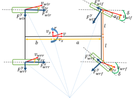
Different quantities associated to EV dynamics during maneuver are shown in Fig. 1. The distance of center of gravity (COG) from front and rear axles are denoted by and respectively. Additionally, denotes half of track width of the EV and EV front wheels are steered by an angle . Longitudinal velocity, lateral velocity and yaw rate of COG of the EV are denoted by , and respectively. Dependence on time is suppressed for better readability. Similarly, , and denote resultant longitudinal force, resultant lateral force at and resultant yaw moment about COG of the EV. The force and moment are generated by forces acting at wheel-road contact. When an EV is performing coupled longitudinal and lateral maneuver, utilized energy is given as:
Here, is energy utilized in maneuver. Assuming that camber angle of each wheel is zero, the relationship between forces and moment at vehicle level with wheel forces are:
Here, and are wheel longitudinal and lateral forces at wheel where and . Throughout the paper, subscripts and are used. Similar to forces, wheel velocities are also related to vehicle velocities and the relationship is given as:
where, and are longitudinal and lateral components of wheel velocity at wheel .
II-B Energy consumed in wheel translation motion
Brake torque and rolling resistance moment resist wheel rotational motion. However, axle torque assist in wheel rotation during acceleration and resist the rotational motion during deceleration in presence of regenerative braking. Therefore, input energy consumed by wheel is
Some part of wheel input energy is used in rotating wheel and wheel longitudinal maneuver while rest is lost due to friction . Energy consumed in wheel longitudinal translation motion is given as:
Here, and denote wheel rotational speed and radius of wheel (same for all the wheels). Wheel lateral forces, generated at tyre-road contact due to steering action, resist wheel motion in order to align with wheels in steered direction and thus dissipate energy. Therefore, lateral forces also contribute to wheel output energy along with longitudinal forces. The output energy of individual wheel is:
where, is energy consumed in wheel lateral translation motion. For RWD vehicles, is positive for rear wheels which contribute to wheel traction energy. The value of is negative for front wheels indicating dissipation of energy due to resisting wheel longitudinal forces during acceleration as well as deceleration. This causes decrease in traction energy and leads to a lower value of resultant traction energy. In absence of regeneration and are lost as thermal energy during braking. However in presence of regenerative braking, energy is not totally lost as thermal energy and some part is recovered as battery energy.
Through simplification of equations, it can be shown that energy consumed in maneuver is same as sum of energy consumed in translation motion of all wheels. Thus,
II-C Input energy from powertrain to wheel
Axle torque contributes to input energy of wheel from powertrain and is given as:
where . Input energy for individual wheels are given below:
For RWD EV, differential output energy, denoted by , is distributed into rear left and right wheels as:
II-D Energy flow from battery to differential
Motor output energy is input to differential and is related to differential output energy as . Here, and are differential efficiency and motor output energy respectively. Motor output energy is given as:
Here, , , , , and are motor torque, motor speed, efficiency of inverter, motor power loss, motor input energy and battery output energy respectively.
With and as terminal voltage and current flowing through battery, output energy of battery is:
It is evident from above energy flow analysis that energy from battery is utilized in rotating wheel and to overcome friction loss, front wheels slippage loss (due to component of resistive wheel longitudinal forces) and cornering loss (due to component of resistive wheel lateral forces). Therefore, overall energy demand for an EV trying to achieve specific longitudinal maneuver over a duration increases in presence of lateral maneuver. Similar analysis can be applied to front wheel driven (FWD) EV.
II-E Energy Flow Simulation Results
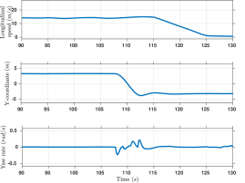
The presented flow of energy can be visualized graphically in terms of power flow from source to maneuver.111Analysis upto next section is carried out for a specific driver behaviour. Results for various driver behavior would qualitatively remain the same. To analyze the energy flow, a simulation study is conducted using Matlab-Simulink [19]. An EV model, consisting of powertrain and planar dynamics, is simulated to track FTP-75 drive cycle for a given driver behaviour. The planar maneuver followed by EV is characterized by longitudinal speed, inertial Y-coordinate and yaw rate. Fig. 2 shows snapshot of maneuver for duration .
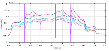
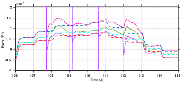
Power flow profile for this small duration of the EV maneuver in absence and presence of regeneration braking is shown in Fig. 3 and 4 respectively.
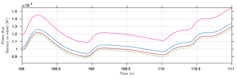
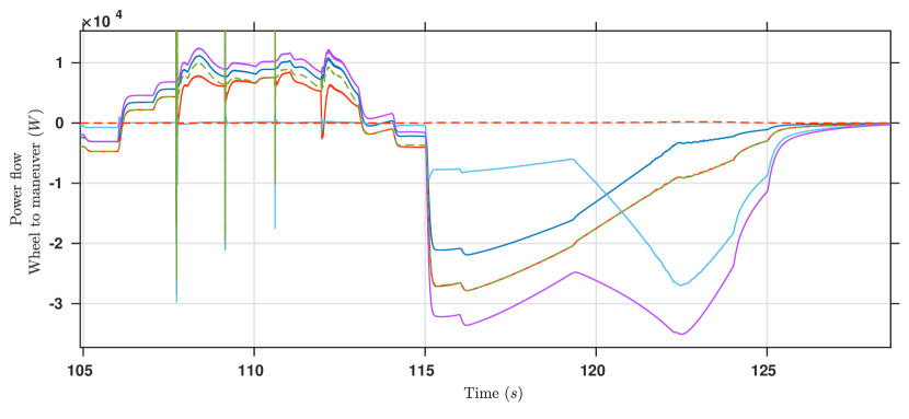
Positive battery power indicates situation when driver is pressing accelerator pedal and energy flows from battery to maneuver. In this case, power corresponding to input energy consumed by wheels is smaller in magnitude compared to battery power due to efficiency factor of motor and differential. Resisting front wheel longitudinal forces causes decrease in magnitude of wheel traction power and leads to resultant traction power with smaller magnitude. The power consumed in maneuver is same as resultant traction power in case of longitudinal motion. However, there is a decrease in power consumed during lateral maneuver due to resistive front wheel lateral forces. Power consumed in wheel rotation and dissipated in tyre-road contact friction loss is at most 2% of power supplied by battery and is negligible. However, the magnitude of power consumed in wheel rotation is not negligible during braking. Instead negative value of this power and power consumed in maneuver, in Fig. 3, indicate that brake mechanism dissipates vehicle maneuver energy and wheel rotational energy as thermal energy. In case of regeneration, negative wheel input power and battery power, shown in Fig. 4, indicates some part of wheel rotation and maneuver energy flows back to battery and rest is dissipated as thermal energy during braking.
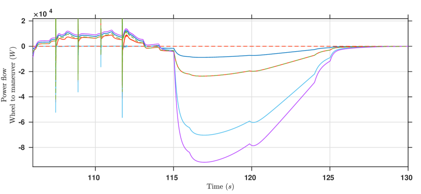
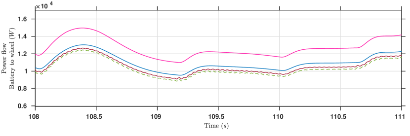
Fig. 5 shows the variation in power requirement of an EV trying to achieve the longitudinal maneuver specified in Fig 3 in absence and presence of specified lane change maneuver. The plot in the top panel corresponds to EV without regeneration and the plot in the bottom panel corresponds to EV with regeneration. It can be observed that power demand increases in presence of lateral maneuver. There is a decrease in longitudinal speed during lateral maneuver due to resisting wheel lateral forces. Driver presses accelerator pedal more to sustain target speed and battery power demand increases as a result. It can also be observed that power demand is less in case of regeneration. It is evident from the discussion that EV lateral dynamics has an impact on battery energy consumption. Therefore, the next section analyzes significance of this impact on energy consumption of an EV driving over long range.
III Effect of Lateral Dynamics on EV Range
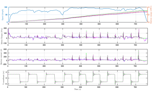
To analyze significance of the effect of lateral dynamics on energy consumption, an EV model with given driver behavior is simulated to track standard drive cycles in two different cases. The two cases are: first is longitudinal maneuver and second is longitudinal maneuver with a lane change every 1km approximately. It can be observed from Fig. 6 that energy consumed for HWFET drive cycle in latter case is more compared to former for EV without regeneration barking. Corresponding motor torque profile has large peak at every lane change indicating increase in energy demand for EV maneuver. Regeneration braking provides EV with facility of energy recuperation. Therefore, energy consumed in presence of regeneration barking is less compared to one without it. The opportunity of recuperation for EV in latter case is less compared to former. Since, cornering forces already assist in braking, amount of negative torque required for braking is less. Similar observation is obtained for other drive cycles such as NEDC and FTP 75.
Various parameters relating energy consumption corresponding to different drive cycles to EV performance are included in Table I-III. Driving range of EV is obtained through extrapolation of consumed battery energy over repetition of drive cycle for a kWh battery. It can be observed that there is a significant decrease in driving range when lane changes are included in maneuver. Thus, neglecting lateral dynamics gives an overestimated range.
| NEDC | ||||
|---|---|---|---|---|
| Parameters | Without Regeneration | With Regeneration | ||
| Without lane changes | With lane changes | Without lane changes | With lane changes | |
| Distance() | ||||
| Battery Energy() | ||||
| Range() | ||||
| FTP 75 | ||||
|---|---|---|---|---|
| Parameters | Without Regeneration | With Regeneration | ||
| Without lane changes | With lane changes | Without lane changes | With lane changes | |
| Distance() | ||||
| Battery Energy() | ||||
| Range() | ||||
| HWFET | ||||
|---|---|---|---|---|
| Parameters | Without Regeneration | With Regeneration | ||
| Without lane changes | With lane changes | Without lane changes | With lane changes | |
| Distance() | ||||
| Battery Energy() | ||||
| Range() | ||||
IV Conclusion
An analysis of energy flow in an EV is carried out and it is observed that there is an increase in demanded energy to achieve specific longitudinal profile in presence of lateral maneuver. It is revealed that state-of-art energy consumption model underestimates the energy consumption profile of an EV during maneuver and lateral dynamics has significant impact on EV performance in real-world driving situation. Therefore, it is essential to include its effect in energy consumption model for different applications such as eco-driving, range prediction, etc. Further analysis to incorporate effect of various environmental factors such as road friction, slope and wind speed during planar maneuver of EV remains a promising direction for future research.
References
- [1] M. S. Kumar and S. T. Revankar, “Development scheme and key technology of an electric vehicle: An overview,” Renewable and Sustainable Energy Reviews, vol. 70, pp. 1266–1285, 2017.
- [2] B. O. Varga, A. Sagoian, and F. Mariasiu, “Prediction of electric vehicle range: A comprehensive review of current issues and challenges,” Energies, vol. 12, no. 5, p. 946, 2019.
- [3] F. Morlock, B. Rolle, M. Bauer, and O. Sawodny, “Forecasts of electric vehicle energy consumption based on characteristic speed profiles and real-time traffic data,” IEEE Transactions on Vehicular Technology, vol. 69, no. 2, pp. 1404–1418, 2019.
- [4] Z. Yi and P. H. Bauer, “Adaptive multiresolution energy consumption prediction for electric vehicles,” IEEE Transactions on Vehicular Technology, vol. 66, no. 11, pp. 10515–10525, 2017.
- [5] A. Desreveaux, A. Bouscayrol, R. Trigui, E. Castex, and J. Klein, “Impact of the velocity profile on energy consumption of electric vehicles,” IEEE transactions on Vehicular Technology, vol. 68, no. 12, pp. 11420–11426, 2019.
- [6] H. Lee, N. Kim, and S. W. Cha, “Model-based reinforcement learning for eco-driving control of electric vehicles,” IEEE Access, vol. 8, pp. 202886–202896, 2020.
- [7] D. Shen, D. Karbowski, and A. Rousseau, “A minimum principle-based algorithm for energy-efficient eco-driving of electric vehicles in various traffic and road conditions,” IEEE Transactions on Intelligent Vehicles, vol. 5, no. 4, pp. 725–737, 2020.
- [8] W. Dib, A. Chasse, P. Moulin, A. Sciarretta, and G. Corde, “Optimal energy management for an electric vehicle in eco-driving applications,” Control Engineering Practice, vol. 29, pp. 299–307, 2014.
- [9] Z. Yi and P. H. Bauer, “Optimal stochastic eco-routing solutions for electric vehicles,” IEEE Transactions on Intelligent Transportation Systems, vol. 19, no. 12, pp. 3807–3817, 2018.
- [10] N. Chakraborty, A. Mondal, and S. Mondal, “Intelligent charge scheduling and eco-routing mechanism for electric vehicles: A multi-objective heuristic approach,” Sustainable Cities and Society, vol. 69, p. 102820, 2021.
- [11] J. A. Oliva, C. Weihrauch, and T. Bertram, “A model-based approach for predicting the remaining driving range in electric vehicles,” in Annual Conference of the PHM Society, vol. 5, 2013.
- [12] P. Ondruska and I. Posner, “Probabilistic attainability maps: Efficiently predicting driver-specific electric vehicle range,” in 2014 IEEE Intelligent Vehicles Symposium Proceedings, pp. 1169–1174, IEEE, 2014.
- [13] C. Fiori, K. Ahn, and H. A. Rakha, “Power-based electric vehicle energy consumption model: Model development and validation,” Applied Energy, vol. 168, pp. 257–268, 2016.
- [14] R. Ristiana, A. S. Rohman, C. Machbub, A. Purwadi, and E. Rijanto, “A new approach of ev modeling and its control applications to reduce energy consumption,” IEEE Access, vol. 7, pp. 141209–141225, 2019.
- [15] J. Han, A. Vahidi, and A. Sciarretta, “Fundamentals of energy efficient driving for combustion engine and electric vehicles: An optimal control perspective,” Automatica, vol. 103, pp. 558–572, 2019.
- [16] T. Wang, C. G. Cassandras, and S. Pourazarm, “Optimal motion control for energy-aware electric vehicles,” Control Engineering Practice, vol. 38, pp. 37–45, 2015.
- [17] F. Ding and H. Jin, “On the optimal speed profile for eco-driving on curved roads,” IEEE Transactions on Intelligent Transportation Systems, vol. 19, no. 12, pp. 4000–4010, 2018.
- [18] L. Li, S. Coskun, F. Zhang, R. Langari, and J. Xi, “Energy management of hybrid electric vehicle using vehicle lateral dynamic in velocity prediction,” IEEE Transactions on Vehicular Technology, vol. 68, no. 4, pp. 3279–3293, 2019.
- [19] MATLAB and Simulink, R2021b. Natick, Massachusetts: The MathWorks Inc., 2021.