Achiral dipoles on a ferromagnet can affect its magnetization direction
Abstract
We demonstrate the possibility of a coupling between the magnetization direction of a ferromagnet and the tilting angle of adsorbed achiral molecules. To illustrate the mechanism of the coupling, we analyze a minimal Stoner model that includes Rashba spin-orbit coupling due to the electric field on the surface of the ferromagnet. The proposed mechanism allows us to study magnetic anisotropy of the system with an extended Stoner-Wohlfarth model, and argue that adsorbed achiral molecules can change magnetocrystalline anisotropy of the substrate. Our research’s aim is to motivate further experimental studies of the current-free chirality induced spin selectivity effect involving both enantiomers.
I Introduction
Chirality induced spin selectivity (CISS) has become an umbrella name for a number of seemingly related experimental reports on the coupling between geometrical chirality and the spin degree of freedom Naaman, Paltiel, and Waldeck (2019); Waldeck, Naaman, and Paltiel (2021); Naaman, Paltiel, and Waldeck (2022); Xu and Mi (2023). Initially, the effect was discovered by analyzing photo-excited electrons after they pass through adsorbed biological molecules Ray et al. (1999); Göhler et al. (2011) and in currents of electrons through organic chiral junctions Xie et al. (2011). Later, the interplay between chirality and the electron’s spin was observed in chemical reactions Zhang et al. (2018); Metzger et al. (2020), in enantioselective adsorption on magnetic substrates Banerjee-Ghosh et al. (2018); Safari et al. (2022); Santra et al. (2023), and even in fully inorganic systems Ghosh et al. (2019); Inui et al. (2020). By now, there is a great collection of experimental set-ups and observables that demonstrate CISS. In spite of this, detailed theoretical understanding of the CISS effect, much needed for a further development of the field, is still lacking Evers et al. (2022); Fransson (2022).
One problem in building theoretical models of CISS is that the experimental platforms differ drastically from one another, and are traditionally studied using independent methods and approaches. This does not rule out the possibility of a unifying mechanism behind the CISS effect; it suggests, however, to study the existing classes of experiments separately. From the theoretical standpoint, it is natural to start by examining systems where the interplay between spin and chirality is observed without applied currents Sukenik et al. (2020); Miwa et al. (2020); Meirzada et al. (2021); Alpern et al. (2021), note also relevant theoretical models in Refs. Volosniev et al., 2021; fransson-nano-2021; fransson-jpcl-2022. First, these systems are usually easier to analyze, as they can be studied using methods developed for steady states. Second, looking into these systems might help to answer fundamental questions about the CISS effect, in particular, about the origin of time-reversal-breaking correlations necessary for spin-selective phenomena. Indeed, systems in equilibrium have vanishing currents, eliminating the key ingredient of many CISS-related theoretical models Gutierrez et al. (2012); Guo and Sun (2012); Medina et al. (2012); Gersten, Kaasbjerg, and Nitzan (2013); Guo and Sun (2014); Matityahu et al. (2016); Diaz et al. (2018); Fransson (2019); Michaeli and Naaman (2019); Dalum and Hedegård (2019); Fransson (2020); Ghazaryan, Lemeshko, and Volosniev (2020); Ghazaryan, Paltiel, and Lemeshko (2020); Alwan and Dubi (2021); Liu et al. (2021); Wolf et al. (2022); Vittmann et al. (2023) from the picture. In the absence of currents, time reversal breaking may occur, e.g., as a result of substrate magnetization Sanvito (2010) or of non-unitary effects (such as dephasing and dissipation) that are used in CISS models Guo and Sun (2012, 2014); Matityahu et al. (2016); Geyer et al. (2019); Volosniev et al. (2021).
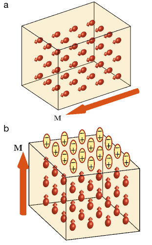
Arguably, the most puzzling observation of current-free CISS experiments is the coupling between the direction of magnetization in the substrate and the tilt of the organic molecules Sukenik et al. (2020); Meirzada et al. (2021). Although this observation is typically explained within the CISS framework, in this contribution we want to highlight the fact that the magnetization of the substrate, , can in principle couple directly to the polarization of the molecular layer, , without the need to involve chirality. For example, a phenomenological term in the form can enter the energy functional since it is allowed by the time-reversal symmetry of the problem. Here, the parameter determines the strength of the effect. Some experimental results Sukenik et al. (2020); Meirzada et al. (2021) can be explained by the term if is negative so that the magnetization prefers to be parallel to the direction of , see Fig. 1. For example, this explains the larger tilting angle for samples with the in-plane easy axis than for the out-of-plane easy axis Sukenik et al. (2020), and also the correlation between the direction of the magnetization and the tilt angle of the molecular layer Meirzada et al. (2021).
As we shall illustrate in this paper, is not the only term allowed by symmetries, and a case-by-case study is probably needed to establish accurate phenomenological models for every system of interest. For example, on the surface of a metal only the normal component of the electric field should play a role, so that the terms of the form become relevant, where is the vector normal to the surface. In any case, the very possibility of a chirality-independent coupling between the magnetization direction and a tilting angle must motivate current-free experimental studies of the CISS effect involving both enantiomers. This might be especially important in light of the observation that, for certain substrates, the effect of chirality on the strength of the coercive field might be a next-to-leading-order effect Miwa et al. (2020).
II Magneto-electric coupling
The key message of our study is that the electric field at the interface between a ferromagnet and a molecular layer can couple to the vector , see Fig. 1. This hypothesis falls into the realm of magneto-electric coupling (MEC) effects in a broad sense Eerenstein, Mathur, and Scott (2006). Many properties of MEC are well-established, therefore, we find it appropriate to review them here only briefly.
It is expected that the interface MEC is very sensitive to the electronic and atomic structure of constituents Niranjan et al. (2010); Kumari and Niranjan (2021), in particular, because reactive metal surfaces of ferromagnetic materials may lead to formation of chemical bonds between the molecules and the substrate Cinchetti, Dediu, and Hueso (2017). Therefore, a microscopic first-principle calculation is required for every experimental set-up to accurately determine the resulting MEC. Here, we do not attempt such a calculation, as our goal is to provide a basic intuition for phenomenological terms that can couple the directions of and . In particular, we illustrate the effect using a toy model that explains a physical mechanism of coupling, and symmetries of the problem.
The mechanism connecting electric and magnetic effects in our case is Rashba spin-orbit coupling (SOC), which is known to be important at surfaces and interfaces Soumyanarayanan et al. (2016). Before introducing the toy model in the following section, we note that there are a number of other effects that can lead to the interplay between magnetization of the surface and adsorbed molecules. For example, the adsorption of molecules can increase the strength of the magnetic exchange interaction on the surface Callsen et al. (2013) and even invert the magnetic anisotropy of thin films under certain conditions Bairagi et al. (2015). These ‘magnetic hardening’ effects rely on chemical bonding between molecular adsorbates and the substrate, and cannot directly explain the experiments where the ferromagnet is coated with goldMeirzada et al. (2021). Screening charge on the surface of a ferromagnetic metal can also modify magnetization of the surface Zhang (1999); Niranjan et al. (2010). However, in this effect the direction of is not important, and therefore it cannot directly explain the experimental data taken for different directions of magnetizationSukenik et al. (2020). Finally, we note that density-functional theory calculations on isolated ferromagnetic films indicate that external electric fields can be used to change the magnetization between in-plane and out-of-plane orientations Duan et al. (2008). This observation is in line with our phenomenological results, see below.
III Electrostatics of the molecular layer
Formulation. The simplest approach to static properties of electrons at interfaces is based upon electrostatics Natan et al. (2007); Monti (2012). In this approach, the main effect of the organic layer is in the change of the electric field across the interface. For simplicity, we assume that the electric field on the substrate is determined completely by the molecules. Furthermore, as we are interested in surface effects, we restrict the motion of electrons to the plane. With these assumptions, we write the following Stoner model (cf. Ref. Gold, 1974),
| (1) |
where is the unity matrix, and is a dispersion relation without SOC and Stoner terms. For simplicity, we assume that is independent of spin. is the Stoner term, which we introduce to account for a ferromagnetic nature of the substrate; here, is the spin operator, is the Stoner parameter and is the polarization of the substrate, see below. If is vanishing, then the direction of defines the direction of magnetization, and a natural quantization axis for the spin with projections: and . The corresponding electronic densities are and , where is the number of particles and is the surface area. The corresponding polarization of the substrate reads . Without loss of generality, we assume that (thus ).
The last term in Eq. (1) describes a Rashba-like spin-orbit coupling Rashba (1960); Bychkov and Rashba (1984); Manchon et al. (2015)
| (2) |
which couples the electric field to electron’s spin, providing the basis for MEC. is a constant that determines the strength of SOC; is a homogeneous (at least in first approximation) electric field, originating from the charge re-organization concurrent to the chemical absorption process for the molecular monolayer.
Since the substrate is metallic, the electric field has to be perpendicular to its surface, . We assume that the component is proportional to , and its amplitude is therefore determined by the tilt angle of the molecular layer, , see Fig. 6 in the Appendix. The assumption is not essential, and used only to simplify the discussion. It is only important that by tilting the angle of the molecules, the value of changes. In general, the direction of is not perpendicular to the surface, and our goal here is to investigate the energy as a function of and the direction of .
For the sake of completeness, it is worth remarking that one must exercise care when working with Eq. (2), since hermiticity of the resulting Hamiltonian is not guaranteed for at least a couple of relevant situations. The first scenario, now well understood in solid-state physics, involves the dimensional reduction, occuring when, for instance, a strong potential confines electrons on an effective one-dimensional ring (see Refs. Meijer, Morpurgo, and Klapwijk, 2002 and Berche, Chatelain, and Medina, 2010 for an extensive discussion about this issue). Second, note that spin-orbit coupling is an inherently relativistic effect as its derivation might be based upon the Dirac theorybransden-quantum-book. The lowest-order relativistic corrections to the Hamiltonian are given bercioux-2015; mondal-2015; mondal-2016; Mondal-2017 by Eq. (2) and one more term, interpreted as the coupling between the angular momentum of a radiation field and the magnetic moment of the electron. For our purpose, Eq. (2) is accurate because the electric field is assumed to be time- and position-independent and the relativistic corrections to the eigenstates are neglected.
Eigenstates of the Hamiltonian. To elucidate the interplay between and the Rashba SOC, we calculate the spectrum of from Eq. (1). To this end, we work in the momentum representation, where the total Hamiltonian is cast in the form
| (3) | ||||
Note that the Pauli matrices anticommute with each other, and therefore, we can easily calculate the spectrum by considering . We derive
| (4) |
where labels the spin manifold.
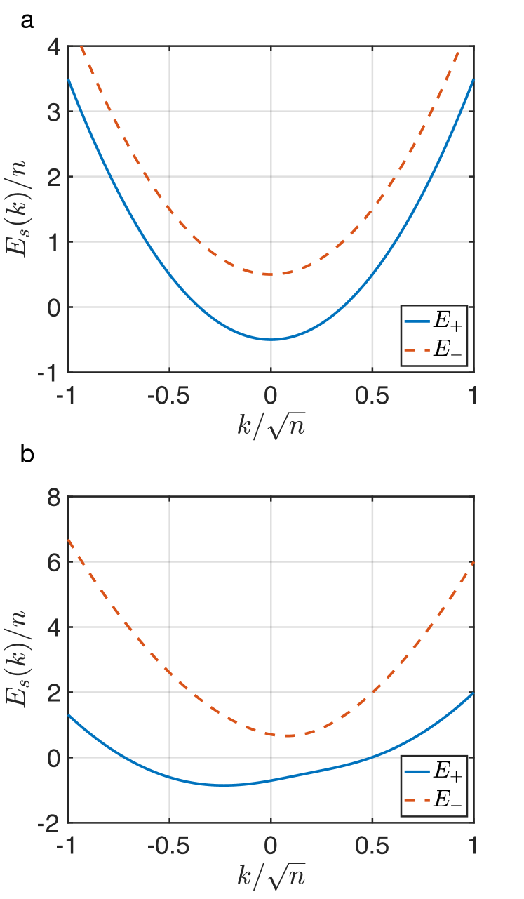
In Fig. 2 we plot the energy spectrum bands as provided by the equation above for (here, ). As a matter of convention, the lower bands have been labelled as . By construction, the Stoner term introduces a gap between the bands, while the Rashba SOC (cf. Eq. (2)) shifts the band minima.
Total energy of the system. The total energy of the system is obtained by summing over the lowest states , namely
| (5) |
where the sum is most easily calculated in the continuum limit: .
To illustrate this energy, we assume that the energy scale associated with SOC is significantly smaller than all other energy scales, i.e., . With this assumption, we write the energy up to -terms as
| (6) |
where . To demonstrate that the change in the energy due to the presence of the organic layer
| (7) |
can depend on the angle , we assume that and , i.e., we work with a strong ferromagnet. In this case, only the first line in Eq. (6) is relevant because there is a high energy price for flipping a spin of an electron. We derive
| (8) |
where is the Fermi energy of the ‘spin-up’ particles. The dependence of on shows that the system prefers to have in-plane magnetization. Note that Eq. (8) contradicts the sketch in Fig. 3. However, this is not a point of concern for two reasons. First, our goal here is to illustrate general principles of coupling, and the overall sign of the derived term may change if other toy models are considered. Second, the surface electric field exists in real materials even without the molecules. Therefore, the following representation of might be more accurate: . If and have different signs and , the situation in Fig. 3 is restored. The most important conclusion of this section is that the strength of the effect presented in Eq. (8) is determined by the tilt angle of the molecules via .
IV Extended Stoner-Wohlfarth model
The discussion in the previous section provides a basis for studying magneto-electric coupling between organic molecules and the ferromagnetic substrate. With it, we can extend the simple Stoner-Wohlfarth model Stoner and Wohlfarth (1948); Tannous and Gieraltowski (2008) and understand the effect of the molecules on magnetic hysteresis and the interplay between the molecular tilting angle and the direction of . Assuming that the ferromagnet has an uniaxial magnetic anisotropy, we write the energy, , as
| (9) |
where the first line is the standard Stoner-Wohlfarth model, and the second line is our extension. Here, is the three-dimensional volume of the ferromagnet; is the anisotropy parameter; is the saturation magnetization; is the magnitude of an external magnetic field; is the vacuum permeability. The last term in Eq. (9) is derived in Eq. 8. It introduces magnetic anisotropy due to the presence of organic molecules. Its strength is determined by
| (10) |
where the parameter is the thickness of the ferromagnet. In what follows, we shall treat the amplitude and the sign of as free parameters, and estimate ‘realistic’ values of only at the end of this section. Finally, we note that we associate the angle of the magnetization with that of , i.e., .
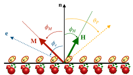
The geometry of the system is presented in Fig. 3. We measure all angles with respect to the normal to the surface. , , and define the angles of the magnetization, external magnetic field and the easy axis, respectively. We assume that and all lie in one plane. This assumption does not change the qualitative nature of our discussion.
Without an external magnetic field. First, we consider the system without an external field ()
| (11) |
For ( is any integer), the minimum of the energy is for either in-plane or out-of-plane direction of . For example, for , we have
| (12) |
The defining dimensionless parameter here is
| (13) |
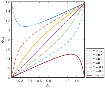
Note that by changing the tilt of the molecules, we can change the direction of the easy axis of the magnet, assuming that , see Fig. 4.
For general values of , the equilibrium is reached when the derivative of the energy with respect to the magnetization direction is zero, , so that
| (14) |
We see that the direction of the equilibrium direction of magnetization changes, which can explain the experimental observation of Ref. Meirzada et al., 2021. For example, for (), we can write
| (15) |
For general values of , we solve the equation numerically, see Fig. 4. Note that the effect of small values of is the most pronounced for .
With an external magnetic field. The extended Stoner-Wohlfarth model provides insight into the modification of the coercive field caused by the adsorbed molecules Miwa et al. (2020). To illustrate this, let us assume an out-of-plane easy axis, , and that the magnetic field is also perpendicular to the surface . In this case, the organic molecular layer simply changes the value of the anisotropy parameter in the standard Stoner-Wohlfarth model, i.e., where
| (16) |
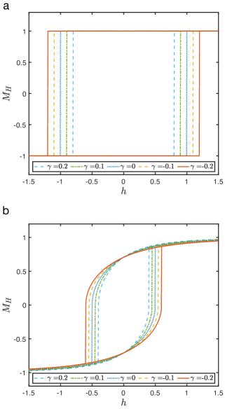
The change of affects the magnetic hysteresis, in particular, the switching field (recall that )
| (17) |
The relative strength of the effect of the adsorbed molecules on the switching field is (see Fig. 5 a)
| (18) |
For general values of , the Stoner-Wohlfarth model is not exactly solvable. Our numerical calculations show that the effect of the parameter is qualitatively similar to the case of , see Fig. 5 b.
Using Eq. (18) and the experimental data Miwa et al. (2020), we can have an-order-of-magnitude estimate for the value of , which is otherwise difficult to calculate because the strength of the SOC effect strongly depends on the electric field, whose accurate value is unknown.
The substrate of thickness nm is made of iron for whichCullity and Graham (2008) eV/. Since the change in the coercive field can be about 10% (so that ), we estimate eV/nm2. Here, we have assumed that the molecules are perpendicular to the surface, . Using the value of and the Fermi energy, eV, we can also estimate the strength of the Rashba SOC: nm – a relatively small valueManchon et al. (2015). Note that if there is an electric field present without the molecules, i.e., , then we actually estimate in this way.
V Conclusions and Outlook
We have argued that the change of the surface electric field caused by adsorbed molecules can affect the magnetocrystalline anisotropy of a ferromagnetic metallic substrate even if molecules are achiral. To illustrate this claim, we have formulated a toy model in which the molecules change the surface electric field, which is coupled to magnetization via a Rashba-like SOC. The strength of coupling is given by the properties of the substrate and therefore no effect should be present for substrates with weak SOC (cf. Refs. Gersten, Kaasbjerg, and Nitzan, 2013; Liu et al., 2021; Adhikari et al., 2022).
Using the results of the toy model, we have introduced an extension of the Stoner-Wohlfarth framework, and calculated the effect of the molecules on the preferred direction of magnetization. In particular, we have shown that the effect of the molecules (for small values of ) can be enhanced by working with a ferromagnet whose easy axis has , motivating experiments with such materials. Finally, we have illustrated the effect of the molecules on the magnetic hysteresis, and estimated phenomenological parameters using available experimental data. Our findings show that isolating the effect of molecular chirality by changing magnetization of the surface is a daunting task, thus motivating further experimental research of chirality induced spin selectivity in current-free set-ups to use both enantiomers.
Let us conclude by making a few remarks. First, note that according to our results the direction of magnetization couples to the dipolar moment of both chiral and achiral molecules, and therefore, our results cannot unravel microscopic origin of the CISS effect. Second, our work does not intend to discard the role of chirality in CISS experiments that explore the realignment of magnetization upon the adsorption of a chiral monolayer BenDor2017. On the contrary, our work aims to motivate further theoretical studies that must contrast and compare the roles of structural chirality and a magneto-electric coupling driven by interface SOC. For instance, the term suggests that can be either parallel or anti-parallel to . In other words, these two directions are energetically degenerate. Chirality then might be a key ingredient to break this degeneracy during the adsorption process leading to the results reported in Ref. BenDor2017. The symmetry-breaking mechanism can be based upon an observation that the helical structure of the molecule is coupled to the angular momentum degree of freedom of the electron Gersten, Kaasbjerg, and Nitzan (2013); Liu et al. (2021); Adhikari et al. (2022). One can speculate that this coupling in the presence of interface SOC can provide an energy barrier during molecular adsorption that depends on chirality and the direction of magnetization, and hence can potentially drive the system into only one of the available energy minima, i.e., with either parallel or antiparallel to depending on chirality.
Although the above mentioned frameworksLiu et al. (2021); Adhikari et al. (2022) deal with time-dependent setups, they might pave the way for a natural extension of our model. Indeed, if we assume that the role of chirality is to filter the orbital angular momentum, then we can implement this filtering in SOC. Another possible extension of our work is to take into account a helical structure of the molecule, which adds to the electric field some additional spatial chirality. To this end, one should study more general forms of the electric field, e.g., , including the terms independent of the tilting angle. Such terms can noticeably modify the overall dependence of observables on . Furthermore, if we consider higher-order electric multipoles it should be possible to also study the effect of chirality. Finally, it is worth investigating the role of the electric field generated by the molecules on the CISS effect with currents, and the effect of other, in particular non-linear, types of SOC that can be present in the substrate.
Acknowledgements.
We thank Zhanybek Alpichshev, Mohammad Reza Safari, Binghai Yan and Yossi Paltiel for enlightning discussions. M.L. acknowledges support by the European Research Council (ERC) Starting Grant No.801770 (ANGULON). A. C. received funding from the European Union’s Horizon Europe research and innovation program under the Marie Skłodowska-Curie grant agreement No. 101062862 - NeqMolRot.Appendix A Electric field of a single dipole
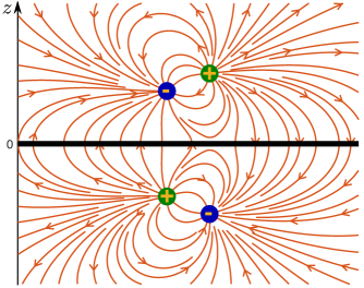
Here, we discuss the electric field on the surface of a metal created by a single dipole. The geometry is shown in Fig. 6. The corresponding electric field is (in cgs units):
| (19) |
where is the position of the charge above the ferromagnet, and is the distance from the charge to the point on the surface, see Fig. 6. For simplicity, we assume a point dipole, , so that , and . This expression shows that the electric field that enters our calculations indeed depends on the direction of the dipoles.
We note that the realistic electric field generated by the molecules is unlikely to be that of a point dipole. It is also not homogeneous, in particular, because the molecules are extended entities. However, the qualitative properties of our main findings should be insensitive to these assumptions.
References
- Naaman, Paltiel, and Waldeck (2019) R. Naaman, Y. Paltiel, and D. H. Waldeck, “Chiral molecules and the electron spin,” Nature Reviews Chemistry 3, 250–260 (2019).
- Waldeck, Naaman, and Paltiel (2021) D. H. Waldeck, R. Naaman, and Y. Paltiel, “The spin selectivity effect in chiral materials,” APL Materials 9 (2021), 10.1063/5.0049150.
- Naaman, Paltiel, and Waldeck (2022) R. Naaman, Y. Paltiel, and D. H. Waldeck, “Chiral induced spin selectivity and its implications for biological functions,” Annual Review of Biophysics 51, 99–114 (2022).
- Xu and Mi (2023) Y. Xu and W. Mi, “Chiral-induced spin selectivity in biomolecules, hybrid organic–inorganic perovskites and inorganic materials: a comprehensive review on recent progress,” Mater. Horiz. , – (2023).
- Ray et al. (1999) K. Ray, S. P. Ananthavel, D. H. Waldeck, and R. Naaman, “Asymmetric scattering of polarized electrons by organized organic films of chiral molecules,” Science 283, 814–816 (1999).
- Göhler et al. (2011) B. Göhler, V. Hamelbeck, T. Z. Markus, M. Kettner, G. F. Hanne, Z. Vager, R. Naaman, and H. Zacharias, “Spin selectivity in electron transmission through self-assembled monolayers of double-stranded DNA,” Science 331, 894–897 (2011).
- Xie et al. (2011) Z. Xie, T. Z. Markus, S. R. Cohen, Z. Vager, R. Gutierrez, and R. Naaman, “Spin specific electron conduction through DNA oligomers,” Nano Letters 11, 4652–4655 (2011).
- Zhang et al. (2018) W. Zhang, K. Banerjee-Ghosh, F. Tassinari, and R. Naaman, “Enhanced electrochemical water splitting with chiral molecule-coated fe3o4 nanoparticles,” ACS Energy Letters 3, 2308–2313 (2018).
- Metzger et al. (2020) T. S. Metzger, S. Mishra, B. P. Bloom, N. Goren, A. Neubauer, G. Shmul, J. Wei, S. Yochelis, F. Tassinari, C. Fontanesi, D. H. Waldeck, Y. Paltiel, and R. Naaman, “The electron spin as a chiral reagent,” Angewandte Chemie International Edition 59, 1653–1658 (2020).
- Banerjee-Ghosh et al. (2018) K. Banerjee-Ghosh, O. B. Dor, F. Tassinari, E. Capua, S. Yochelis, A. Capua, S.-H. Yang, S. S. P. Parkin, S. Sarkar, L. Kronik, L. T. Baczewski, R. Naaman, and Y. Paltiel, “Separation of enantiomers by their enantiospecific interaction with achiral magnetic substrates,” Science 360, 1331–1334 (2018).
- Safari et al. (2022) M. R. Safari, F. Matthes, K.-H. Ernst, D. E. Bürgler, and C. M. Schneider, “Enantiospecific adsorption on a ferromagnetic surface at the single-molecule scale,” (2022), arXiv:2211.12976 [cond-mat.mtrl-sci] .
- Santra et al. (2023) K. Santra, Y. Lu, D. H. Waldeck, and R. Naaman, “Spin selectivity damage dependence of adsorption of dsdna on ferromagnets,” The Journal of Physical Chemistry B 127, 2344–2350 (2023), pMID: 36888909.
- Ghosh et al. (2019) K. B. Ghosh, W. Zhang, F. Tassinari, Y. Mastai, O. Lidor-Shalev, R. Naaman, P. Möllers, D. Nürenberg, H. Zacharias, J. Wei, E. Wierzbinski, and D. H. Waldeck, “Controlling chemical selectivity in electrocatalysis with chiral cuo-coated electrodes,” The Journal of Physical Chemistry C 123, 3024–3031 (2019).
- Inui et al. (2020) A. Inui, R. Aoki, Y. Nishiue, K. Shiota, Y. Kousaka, H. Shishido, D. Hirobe, M. Suda, J.-i. Ohe, J.-i. Kishine, H. M. Yamamoto, and Y. Togawa, “Chirality-Induced Spin-Polarized State of a Chiral Crystal ,” Phys. Rev. Lett. 124, 166602 (2020).
- Evers et al. (2022) F. Evers, A. Aharony, N. Bar-Gill, O. Entin-Wohlman, P. Hedegård, O. Hod, P. Jelinek, G. Kamieniarz, M. Lemeshko, K. Michaeli, V. Mujica, R. Naaman, Y. Paltiel, S. Refaely-Abramson, O. Tal, J. Thijssen, M. Thoss, J. M. van Ruitenbeek, L. Venkataraman, D. H. Waldeck, B. Yan, and L. Kronik, “Theory of chirality induced spin selectivity: Progress and challenges,” Advanced Materials 34, 2106629 (2022).
- Fransson (2022) J. Fransson, “The chiral induced spin selectivity effect what it is, what it is not, and why it matters,” Israel Journal of Chemistry 62, e202200046 (2022).
- Sukenik et al. (2020) N. Sukenik, F. Tassinari, S. Yochelis, O. Millo, L. T. Baczewski, and Y. Paltiel, “Correlation between ferromagnetic layer easy axis and the tilt angle of self assembled chiral molecules,” Molecules 25 (2020), 10.3390/molecules25246036.
- Miwa et al. (2020) S. Miwa, K. Kondou, S. Sakamoto, A. Nihonyanagi, F. Araoka, Y. Otani, and D. Miyajima, “Chirality-induced effective magnetic field in a phthalocyanine molecule,” Applied Physics Express 13, 113001 (2020).
- Meirzada et al. (2021) I. Meirzada, N. Sukenik, G. Haim, S. Yochelis, L. T. Baczewski, Y. Paltiel, and N. Bar-Gill, “Long-time-scale magnetization ordering induced by an adsorbed chiral monolayer on ferromagnets,” ACS Nano 15, 5574–5579 (2021), pMID: 33591720.
- Alpern et al. (2021) H. Alpern, M. Amundsen, R. Hartmann, N. Sukenik, A. Spuri, S. Yochelis, T. Prokscha, V. Gutkin, Y. Anahory, E. Scheer, J. Linder, Z. Salman, O. Millo, Y. Paltiel, and A. Di Bernardo, “Unconventional meissner screening induced by chiral molecules in a conventional superconductor,” Phys. Rev. Mater. 5, 114801 (2021).
- Gutierrez et al. (2012) R. Gutierrez, E. Díaz, R. Naaman, and G. Cuniberti, “Spin-selective transport through helical molecular systems,” Phys. Rev. B 85, 081404 (2012).
- Guo and Sun (2012) A.-M. Guo and Q.-f. Sun, “Spin-selective transport of electrons in dna double helix,” Phys. Rev. Lett. 108, 218102 (2012).
- Medina et al. (2012) E. Medina, F. López, M. A. Ratner, and V. Mujica, “Chiral molecular films as electron polarizers and polarization modulators,” EPL (Europhysics Letters) 99, 17006 (2012).
- Gersten, Kaasbjerg, and Nitzan (2013) J. Gersten, K. Kaasbjerg, and A. Nitzan, “Induced spin filtering in electron transmission through chiral molecular layers adsorbed on metals with strong spin-orbit coupling,” The Journal of Chemical Physics 139, 114111 (2013).
- Guo and Sun (2014) A.-M. Guo and Q.-F. Sun, “Spin-dependent electron transport in protein-like single-helical molecules,” Proceedings of the National Academy of Sciences 111, 11658–11662 (2014).
- Matityahu et al. (2016) S. Matityahu, Y. Utsumi, A. Aharony, O. Entin-Wohlman, and C. A. Balseiro, “Spin-dependent transport through a chiral molecule in the presence of spin-orbit interaction and nonunitary effects,” Phys. Rev. B 93, 075407 (2016).
- Diaz et al. (2018) E. Diaz, P. Albares, P. G. Estevez, J. M. Cerveró, C. Gaul, E. Diez, and F. Domínguez-Adame, “Spin dynamics in helical molecules with nonlinear interactions,” New Journal of Physics 20, 043055 (2018).
- Fransson (2019) J. Fransson, “Chirality-induced spin selectivity: The role of electron correlations,” The Journal of Physical Chemistry Letters 10, 7126–7132 (2019).
- Michaeli and Naaman (2019) K. Michaeli and R. Naaman, “Origin of spin-dependent tunneling through chiral molecules,” The Journal of Physical Chemistry C 123, 17043–17048 (2019).
- Dalum and Hedegård (2019) S. Dalum and P. Hedegård, “Theory of chiral induced spin selectivity,” Nano Letters 19, 5253–5259 (2019), pMID: 31265313.
- Fransson (2020) J. Fransson, “Vibrational origin of exchange splitting and ”chiral-induced spin selectivity,” Phys. Rev. B 102, 235416 (2020).
- Ghazaryan, Lemeshko, and Volosniev (2020) A. Ghazaryan, M. Lemeshko, and A. G. Volosniev, “Filtering spins by scattering from a lattice of point magnets,” Communications Physics 3 (2020), 10.1038/s42005-020-00445-8.
- Ghazaryan, Paltiel, and Lemeshko (2020) A. Ghazaryan, Y. Paltiel, and M. Lemeshko, “Analytic model of chiral-induced spin selectivity,” The Journal of Physical Chemistry C 124, 11716–11721 (2020), pMID: 32499842.
- Alwan and Dubi (2021) S. Alwan and Y. Dubi, “Spinterface origin for the chirality-induced spin-selectivity effect,” Journal of the American Chemical Society 143, 14235–14241 (2021), pMID: 34460242.
- Liu et al. (2021) Y. Liu, J. Xiao, J. Koo, and B. Yan, “Chirality-driven topological electronic structure of DNA-like materials,” Nature Materials 20, 638–644 (2021).
- Wolf et al. (2022) Y. Wolf, Y. Liu, J. Xiao, N. Park, and B. Yan, “Unusual spin polarization in the chirality-induced spin selectivity,” ACS Nano 16, 18601–18607 (2022), pMID: 36282509.
- Vittmann et al. (2023) C. Vittmann, J. Lim, D. Tamascelli, S. F. Huelga, and M. B. Plenio, “Spin-dependent momentum conservation of electron–phonon scattering in chirality-induced spin selectivity,” The Journal of Physical Chemistry Letters 14, 340–346 (2023), pMID: 36625481.
- Sanvito (2010) S. Sanvito, “The rise of spinterface science,” Nature Physics 6, 562–564 (2010).
- Geyer et al. (2019) M. Geyer, R. Gutierrez, V. Mujica, and G. Cuniberti, “Chirality-induced spin selectivity in a coarse-grained tight-binding model for helicene,” The Journal of Physical Chemistry C 123, 27230–27241 (2019).
- Volosniev et al. (2021) A. G. Volosniev, H. Alpern, Y. Paltiel, O. Millo, M. Lemeshko, and A. Ghazaryan, “Interplay between friction and spin-orbit coupling as a source of spin polarization,” Phys. Rev. B 104, 024430 (2021).
- Eerenstein, Mathur, and Scott (2006) W. Eerenstein, N. D. Mathur, and J. F. Scott, “Multiferroic and magnetoelectric materials,” Nature 442, 759–765 (2006).
- Niranjan et al. (2010) M. K. Niranjan, C.-G. Duan, S. S. Jaswal, and E. Y. Tsymbal, “Electric field effect on magnetization at the fe/MgO(001) interface,” Applied Physics Letters 96, 222504 (2010).
- Kumari and Niranjan (2021) P. K. Kumari and M. K. Niranjan, “Interface magnetoelectric effect and its sensitivity on interface structures in fe/agnbo3 and srruo3/agnbo3 heterostructures: A first-principles investigation,” Journal of Magnetism and Magnetic Materials 517, 167372 (2021).
- Cinchetti, Dediu, and Hueso (2017) M. Cinchetti, V. A. Dediu, and L. E. Hueso, “Activating the molecular spinterface,” Nature Materials 16, 507–515 (2017).
- Soumyanarayanan et al. (2016) A. Soumyanarayanan, N. Reyren, A. Fert, and C. Panagopoulos, “Emergent phenomena induced by spin–orbit coupling at surfaces and interfaces,” Nature 539, 509–517 (2016).
- Callsen et al. (2013) M. Callsen, V. Caciuc, N. Kiselev, N. Atodiresei, and S. Blügel, “Magnetic hardening induced by nonmagnetic organic molecules,” Phys. Rev. Lett. 111, 106805 (2013).
- Bairagi et al. (2015) K. Bairagi, A. Bellec, V. Repain, C. Chacon, Y. Girard, Y. Garreau, J. Lagoute, S. Rousset, R. Breitwieser, Y.-C. Hu, Y. C. Chao, W. W. Pai, D. Li, A. Smogunov, and C. Barreteau, “Tuning the magnetic anisotropy at a molecule-metal interface,” Phys. Rev. Lett. 114, 247203 (2015).
- Zhang (1999) S. Zhang, “Spin-dependent surface screening in ferromagnets and magnetic tunnel junctions,” Phys. Rev. Lett. 83, 640–643 (1999).
- Duan et al. (2008) C.-G. Duan, J. P. Velev, R. F. Sabirianov, Z. Zhu, J. Chu, S. S. Jaswal, and E. Y. Tsymbal, “Surface magnetoelectric effect in ferromagnetic metal films,” Phys. Rev. Lett. 101, 137201 (2008).
- Natan et al. (2007) A. Natan, L. Kronik, H. Haick, and R. Tung, “Electrostatic properties of ideal and non-ideal polar organic monolayers: Implications for electronic devices,” Advanced Materials 19, 4103–4117 (2007).
- Monti (2012) O. L. A. Monti, “Understanding interfacial electronic structure and charge transfer: An electrostatic perspective,” The Journal of Physical Chemistry Letters 3, 2342–2351 (2012).
- Gold (1974) A. V. Gold, “Review paper: Fermi surfaces of the ferromagnetic transition metals,” Journal of Low Temperature Physics 16, 3–42 (1974).
- Rashba (1960) E. Rashba, Sov. Phys.-Solid State 2, 1109 (1960).
- Bychkov and Rashba (1984) Y. A. Bychkov and É. I. Rashba, “Properties of a 2D electron gas with lifted spectral degeneracy,” Soviet Journal of Experimental and Theoretical Physics Letters 39, 78 (1984).
- Manchon et al. (2015) A. Manchon, H. C. Koo, J. Nitta, S. M. Frolov, and R. A. Duine, “New perspectives for rashba spin–orbit coupling,” Nature Materials 14, 871–882 (2015).
- Meijer, Morpurgo, and Klapwijk (2002) F. E. Meijer, A. F. Morpurgo, and T. M. Klapwijk, “One-dimensional ring in the presence of rashba spin-orbit interaction: Derivation of the correct hamiltonian,” Phys. Rev. B 66, 033107 (2002).
- Berche, Chatelain, and Medina (2010) B. Berche, C. Chatelain, and E. Medina, “Mesoscopic rings with spin-orbit interactions,” European Journal of Physics 31, 1267 (2010).
- Stoner and Wohlfarth (1948) E. C. Stoner and E. P. Wohlfarth, “A mechanism of magnetic hysteresis in heterogeneous alloys,” Philosophical Transactions of the Royal Society of London. Series A, Mathematical and Physical Sciences 240, 599–642 (1948).
- Tannous and Gieraltowski (2008) C. Tannous and J. Gieraltowski, “The stoner–wohlfarth model of ferromagnetism,” European Journal of Physics 29, 475 (2008).
- Cullity and Graham (2008) B. D. Cullity and C. D. Graham, Introduction to Magnetic Materials (2nd ed.) (Wiley-IEEE Press., 2008).
- Adhikari et al. (2022) Y. Adhikari, T. Liu, H. Wang, Z. Hua, H. Liu, E. Lochner, P. Schlottmann, B. Yan, J. Zhao, and P. Xiong, “Interplay of structural chirality, electron spin and topological orbital in chiral molecular spin valves,” (2022), arXiv:2209.08117 [cond-mat.mtrl-sci] .