X-ray diffraction from dislocation half-loops in epitaxial films
Abstract
X-ray diffraction from dislocation half-loops consisting of a misfit segment and two threading arms extending from it to the surface is calculated by the Monte Carlo method. The diffraction profiles and reciprocal space maps are controlled by the ratio of the total lengths of the misfit and the threading segments of the half-loops. A continuous transformation from the diffraction characteristic of misfit dislocations to that of threading dislocations with increasing thickness of an epitaxial film is studied. Diffraction from dislocations with edge and screw threading arms is considered and the contributions of both types of dislocations are compared.
I Introduction
Misfit dislocations are the most common mode of strain relaxation in epitaxial films [1, 2, 3, 4]. Since the dislocation lines cannot terminate inside a crystal, a misfit dislocation is accompanied by threading arms that extend to the surface (or terminate at an incoherent boundary; we do not consider this case here). The glide of the threading arm under the action of epitaxial strain is the most prominent mechanism of strain relaxation [5]. Threading dislocations passing through the active region of a heteroepitaxial structure lead to a degradation of its electronic properties, whereas misfit dislocations, if located at the interface of a buffer layer below the active region, may have no negative effect. Therefore, a separate determination of misfit and threading dislocations is of primary interest in the characterization of heterostructures for electronic and optoelectronic applications. The density of threading dislocations can be very low if the dislocations glide over long distances, up to the entire length of the sample. At the other extreme, epitaxial gallium nitride is a well-known example of a crystal with high threading dislocation densities [6].
Shifts in the positions of the X-ray diffraction peaks due to relaxation of the average strain by misfit dislocations are commonly used to detect strain relaxation and the corresponding misfit dislocation density [7]. Dislocations also cause inhomogeneous strain, leading to additional diffuse scattering at low dislocation densities and to a broadening of the X-ray peaks at high dislocation densities. The interpretation of the diffraction peak profiles is not as straightforward as that of the mean strain due to dislocations, since the positions of the dislocations may be correlated for kinetic or energetic reasons. The elastic energy of a dislocation array is reduced when misfit dislocations reduce fluctuations in the mean distances between dislocations, from a random to a more periodic arrangement. Threading dislocations reduce the elastic energy when dislocations with opposite Burgers vectors are closer together to compensate for long-range strain.
The theory of X-ray diffraction from misfit [8] and threading [9] dislocations takes these correlations into account and shows that the diffraction peak profiles are sensitive to them. Scattering from misfit dislocations cannot be neglected even in situations where the threading dislocations dominate. Reciprocal space maps of GaN films several microns thick, where threading dislocations are expected to dominate, also showed a significant scattering from misfit dislocations [10, 11]. In these studies, misfit and threading dislocations were considered as two separate dislocation arrays uncorrelated with each other.
It is more appropriate to model the dislocation distribution by dislocation half-loops consisting of a misfit segment and two threading arms extending from it to the surface. The two threading segments have opposite displacement fields, corresponding to opposite directions of the dislocation lines when the Burgers vector is kept constant along the half-loop. Equivalently, the two threading segments can be considered to have opposite Burgers vectors, if the dislocation line directions are taken to be the same. These threading dislocations screen the strain field from each other and provide a model of the dislocation correlations that reduce the elastic energy of the film [12]. By varying the relative lengths of the misfit and threading segments, one can go from the limiting case of misfit dislocations to the opposite limit of threading dislocations. The elastic field of a dislocation half-loop is quite complicated (see Supporting Information) and the diffraction from the half-loops can hardly be studied analytically. However, the X-ray diffraction from a statistical distribution of defects with known elastic fields can be calculated by the Monte Carlo method [13, 12].
The aim of the present work is to model the X-ray diffraction from dislocation half-loops. We follow a transformation of the reciprocal space maps and the diffraction profiles with increasing film thickness while keeping the misfit dislocation density constant. In this way a change from the diffraction pattern characteristic of misfit dislocations to that of threading dislocations can be analyzed. We show that the parameter controlling this transformation is the ratio of the total lengths of misfit and threading dislocations, or equivalently, the ratio of the mean length of the misfit segment to the film thickness. We find that this transformation is rather smooth and also depends on the inclination of the actual diffraction vector to the surface. We compare the effects of the half-loops with the edge and screw dislocation types of the threading arms, and find that they both contribute to the symmetric Bragg reflections.
II Monte Carlo simulation of X-ray diffraction
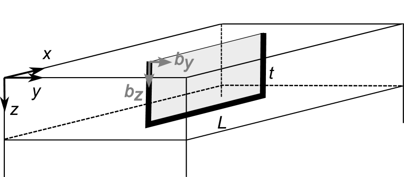
We study the X-ray diffraction from the dislocation half-loops sketched in Fig. 1. Threading arms are assumed to be straight and perpendicular to the film surface. Two types of dislocations are considered. Dislocations with edge threading arms (denoted by in Fig. 1) have Burgers vectors normal to the half-loop plane. Such half-loops correspond to the insertion (or removal, depending on the sense of the mismatch) of a rectangular piece of the extra atomic plane, bounded by the dislocation line and shadowed in Fig. 1. It releases the mismatch between the film and the substrate. The second type of dislocations has screw threading dislocation arms (denoted by in Fig. 1). Their misfit segments provide a local tilt of the film. For these half-loops, Burgers vectors with opposite signs are taken with equal probability, so there is no net tilt of the film.
We take the density of the threading dislocation arms and the mean length of the misfit segment as two parameters characterizing the dislocation ensemble. The misfit dislocation density is therefore , since each half-loop has two threading arms. We note that the threading dislocation density and the misfit dislocation density have different dimensionalities. Threading dislocation density is the number of threading dislocations per unit area of the surface, or more generally, the total length of the threading dislocations per unit volume. Misfit dislocation density is the number of dislocations per unit length of interface, or more generally, the total length of the dislocation lines per unit area of interface.
A parameter that controls the relative contributions of misfit and threading dislocations is the ratio of the mean length of the misfit segment to the film thickness . One can also compare the total length of misfit dislocations per unit area of the interface with that of threading dislocations , since the length of each threading segment is . Given the definition of above, this ratio is simply . Another parameter of the dislocation array is the dimensionless parameter introduced by Wilkens [14, 15] to characterize the screening of the dislocation strain by the surrounding dislocations. It is equal to the ratio of the mean distance between threading dislocations with opposite Burgers vectors (assuming the same dislocation line directions of the threading segments) to the mean distance between threading dislocations , so that .
The Monte Carlo simulations below are performed for an example of a GaN epitaxial film. The positions of the dislocation half-loops are random and uncorrelated. The lengths of the misfit segments have a lognormal distribution with the standard deviation . The misfit segments of the half-loops run in three equivalent directions with equal probability. The length of the Burgers vector of a half-loop with edge threading arms is nm, while that of the half-loop with screw threading arms is nm. The displacement field of a half-loop, satisfying the elastic boundary conditions of the free surface, is constructed from the displacement field of an angular dislocation near the free surface [16] and that of a dislocation normal to the surface [17]. Details of the construction and the analytical expressions for all components of the displacements are given in the Supplementary Information.
The choice of Poisson’s ratio to model dislocations in GaN is somewhat ambiguous. In strain relaxation problems for elastically anisotropic epitaxial films, the Poisson ratio is commonly chosen to give the same vertical strain as in the isotropic approximation. For GaN(0001) this requirement gives , where are the anisotropic elastic moduli. The value is obtained using elastic moduli of GaN from Ref. [18]. The measured values of vary from 0.15 to 0.23 [19]. On the other hand, the strain field of a straight edge dislocation with dislocation line direction in an anisotropic hexagonal crystal coincides with the isotropic solution when the Poisson ratio is taken to be [20]. Using the elastic moduli of GaN [18], Poisson’s ratio is . We use the latter value in the Monte Carlo simulations below, to get a better representation of the strain fields of the threading dislocation arms.
The diffracted intensity is a Fourier transform of the correlation function to reciprocal space. Here and are the coordinates of two points inside the crystal, is the total displacement due to all dislocations (equal to the sum of the displacement fields of individual dislocations due to linear elasticity) calculated in these two points, and is the diffraction vector. The statistical average over the dislocation ensemble and the Fourier transform can be performed simultaneously in one and the same Monte Carlo integration [13]. This integration is time consuming, especially when dislocation densities are large and low intensities at asymptotes are of interest: the integration is a summation of complex numbers of modulus 1 to finally obtain a real number which is much less than one.
When the dislocation density is large and hence the mean-squared strain is large, only correlations between closely spaced points and are of importance [21]. The expansion allows to reduce the X-ray intensity calculation to the calculation of the probability density of the respective distortion components [22, 23]. Specifically, the intensity in the reciprocal space map is calculated as the joint probability density of the distortions and . These distortions depend on a depth of the point in the epitaxial film at which they are calculated. Therefore, an integration over is performed from the surface to the interface . As is usual for a Monte Carlo simulation, this integration does not require any additional computational effort: the point is randomly and homogeneously seeded on the interval . Similarly, the intensity in a double-crystal scan with an open detector, in particular the scan in skew geometry, is calculated as the probability density of the distortion , where is a unit vector in the direction of the diffracted beam and the integration of the probability density over is performed, as above. This expression for the distortion component was derived in Appendix A of Ref. [24] and is re-derived in the Supplementary Information in more familiar Cartesian coordinates. The wave vector is related to the angular deviation by , where is the Bragg angle of the actual reflection. The calculation of the strain probability density distribution is orders of magnitude faster than the straightforward calculation mentioned above because it avoids summing the oscillating complex terms.
This Monte Carlo calculation is ideally suited to parallel computing as each realization of the random dislocation distribution can be computed independently and the partial sums obtained on different processors can be added at the end. We use the extension to Fortran, which was added to the language standard in 2008. In practice, the parallel computations require only a few lines of code to be modified and are performed on 128 cores without any loss of computational efficiency.
Monte Carlo simulations are performed on an Epyc™ 7763 compute server. Diffraction profiles and maps are typically computed in less than 1 minute with sufficient accuracy to reveal the features of the intensity distribution. Each of the curves and maps presented below took several hours to reduce the statistical noise. As the statistical error decreases as , where is the number of repetitions, the one-minute runs are only an order of magnitude less accurate in intensity. The computation time can be reduced by choosing larger steps in the angles in the curves and wave vectors in the maps. On the other hand, most of the computation time is the calculation of the dislocation displacements by analytical formulae presented in the Supplementary Information, which leaves very little room for improvement. The calculation requires memory for an array of the calculated intensity and an array of the coordinates of the dislocation in an actual realization of their distribution, which together do not exceed several megabytes per core.
III Results
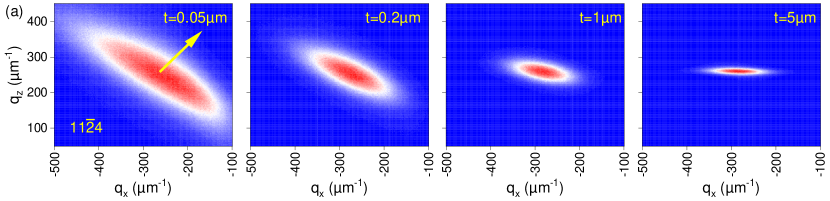
Let us consider the X-ray diffraction from dislocation half-loops with edge threading arms. We assume a threading dislocation density cm-2 and a mean length of the misfit segments µm. Figure 2(a) shows a transformation of the reciprocal space maps with increasing film thickness. For a thickness µm, which is small compared to the misfit segment length, the misfit dislocations dominate the diffraction. The reciprocal space map has the same features as that of infinitely long misfit dislocations [8]. It is extended in the direction almost perpendicular to the direction of the diffraction vector indicated by an arrow in the figure (these directions need not be exactly perpendicular to each other since as this is not required by symmetry). In the opposite limit, where the thickness µm is large compared to the misfit segment length, the diffraction is dominated by threading dislocation arms. Since threading dislocations are parallel straight lines in real space, their diffraction pattern in the reciprocal space is a disc perpendicular to the dislocation line [10, 11]. A section of the disc through the scattering plane gives the horizontal streak in the map. The maps in Fig. 2(a) show a gradual transition from one limit to the other. At thickness µm, five times smaller than the misfit segment length, the diffraction pattern already differs from that for misfit dislocations. At thickness µm, five times larger than the misfit segment length, there is still a finite width of the intensity spot in the direction.
Figure 2(b) shows diffraction profiles in skew geometry [25, 26, 9] for the same film thicknesses and for three reflections, a symmetric reflection (left), a slightly asymmetric reflection (middle), and a highly asymmetric reflection (right). The intensities calculated by the Monte Carlo method are seen as noisy lines, while smooth lines of the same colors are the fits discussed below. Let us start the analysis with the symmetric reflection. Since straight edge dislocations in an infinite medium produce strain only in the plane normal to the dislocation line, it is expected that edge threading dislocations do not cause any broadening of the symmetric reflections. However, the plot in Fig. 2(b) shows that the total effect of the strain field of the misfit segment and the strain due to stress relaxation at the free surface of the threading segments of the half-loop give rise to a diffraction peak broadening even at a thickness of 5 µm.
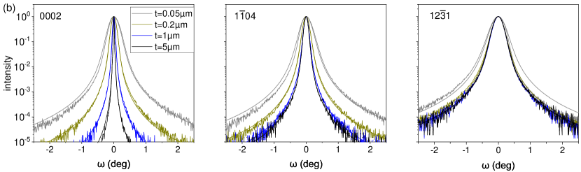
In the usual treatment of the broadening of the symmetric reflections as a manifestation of the screw dislocations, this broadening would be interpreted as a density of screw dislocations. The smooth lines in the plots of Fig. 2(b) are the fits proposed in Ref. [9]. They include two parameters, the dislocation density and the length of the strain field screening (or the dimensionless parameter ). An apparent density of screw threading dislocations, obtained in the fit of the 0002 reflection for the film thickness of 5 µm, is cm The apparent density of screw dislocations increases with the decreasing film thickness, as can be seen from the plots, and reaches cm-2 for a film thickness of 0.05 µm.
At the opposite extreme of a highly asymmetric reflection in the right plot of Fig. 2(b), the strain due to edge threading arms dominates. The diffraction profiles almost coincide for the film thicknesses of µm and above. A slightly asymmetric reflection in the middle plot of Fig. 2(b) shows an intermediate behavior: for thicknesses less than 1 µm, the misfit segment of the half-loop makes a significant contribution.
Figures 2(c) and 2(d) summarize the results of the fits made by the model for infinitely long edge threading dislocations [9]. These fits are represented by smooth lines in Fig. 2(b). A total of 19 diffraction profiles in different asymmetric reflections in skew geometry are calculated by the Monte Carlo method. The apparent density of edge threading dislocations and the corresponding apparent parameter are obtained in the fits. The results for different reflections are compared by plotting these apparent parameters as a function of the angle between the diffraction vector and the film surface. corresponds to diffraction in the surface plane, and to symmetric reflections. The symmetric reflections are not included in Figs. 2(c) and 2(d) since they have been fitted to screw rather than edge threading dislocations.
The results for the film thickness of 5 µm are shown in Figs. 2(c) and 2(d) by full squares, deliberately made larger than the symbols for the other thicknesses, as they come closest to the model of infinite threading dislocations assumed by the fits. The dislocation density obtained in the fit for this film thickness is quite close to the density of cm-2 modeled in the Monte Carlo simulations. This result confirms the consistency between the present Monte Carlo simulations and the fits by the formulae from Ref. [9]. Figure 2(c) shows that as the thickness decreases, the misfit parts of the half-loops make progressively larger contributions. The apparent density of edge dislocations can be 6 times larger than the real density. It can also be seen that the apparent density systematically depends on the inclination angle of the reflection: the less asymmetric reflections give a larger apparent density. This dependence can help to recognize the contribution of misfit dislocations.
The input value of the parameter in the Monte Carlo simulations is . The values obtained in the fit are several times larger and show a large scatter even for the 5 µm film thickness, where the threading dislocations dominate. This result is not surprising: as it was discussed in Ref. [9], the fit does not take into account the orientation factors involved in this parameter. As a result, the accuracy of the dislocation correlation determination is lower than that of the dislocation density determination. As it has been also discussed in Ref. [12], the consideration of these orientation factors is a rather complicated task. On the other hand, it is the dislocation density rather than the dislocation correlations that is of primary interest.
Figure 2(e) shows the full widths at half maxima (FWHMs) of the peaks obtained from the Monte Carlo simulation. The data are shown for the film thicknesses of 0.05 µm and 5 µm. The points from the intermediate thicknesses (not shown) are scattered in between. The FWHMs are used to estimate the dislocation density by a popular, because of its extreme simplicity, formula [27]. This formula is used in symmetric or asymmetric reflections with the Burgers vector equal to either or lattice parameter of GaN to obtain the densities of either screw or edge dislocations. The correct use of this formula for edge dislocations implies the use of twist, i.e., extrapolation of the peak widths in Fig. 2(e) to [26].
When the threading dislocation arms are long and dominate in the scattering (full squares), the FWHMs of the asymmetric reflections in Fig. 2(e) increase with the increasing inclination of the reflection (the angle decreases). The same dependence is observed in experiments [28, 26, 9]. Extrapolation to gives a “twist” of , which according to the above formula gives a threading dislocation density of cm-2, about half of the threading dislocation density used on input in the Monte Carlo simulations. Thus, this simple formula gives a reasonable estimate of the threading dislocation density, with some underestimation. Further Monte Carlo simulations (not presented here) show that this underestimation is systematic. The reflections for a thin epitaxial film, shown by triangles in Fig. 2(e), give a large scatter of the FWHMs of different reflections and, on average, a similar “twist”. Hence, the FWHM based determination of the threading dislocation density gives the same underestimate. The FWHMs of the symmetric reflections, shown by the points at in Fig. 2(e), depend significantly on the order of the reflections. The 0002 reflection would give an apparent density of screw dislocations of cm-2 for the 5 µm thick film and cm-2 for the 0.05 µm thick film.
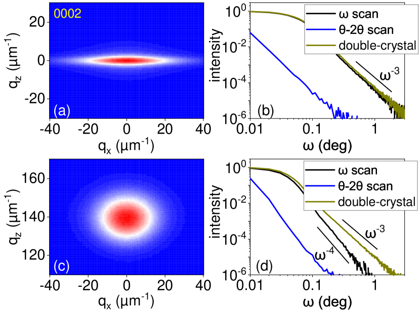
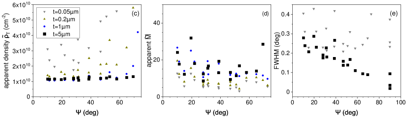
Figure 3 shows the reciprocal space maps and the diffraction profiles in symmetric 0002 reflection of dislocation half-loops with screw (top) and edge (bottom) threading arms. In both cases the mean length of the misfit segments and the film thickness are taken to be the same, µm and µm. The dislocation densities differ by an order of magnitude, half-loops with screw threading arms of density cm-2 are compared with half-loops with the edge threading arms of density cm-2.
The screw threading arms dominate in the diffraction pattern of the respective half-loops, since the displacement due to a screw dislocation is along the diffraction vector. As a result, the diffraction intensity in the map of Fig. 3(a) is extended in the lateral direction, perpendicular to the direction of the screw arms. The scan in the direction in the map, which coincides with the scan in the symmetric reflection, collects all the diffracted intensity. Figure 3(b) shows that the scan and the double crystal scan almost coincide and have the expected asymptote.
The edge threading arms contribute to diffraction in a symmetric Bragg reflection only due to the strain resulting from elastic relaxation at the free surface, since the displacement field of the edge threading dislocation in infinite medium is perpendicular to the diffraction vector. The intensity in the reciprocal space map in Fig. 3(c) is mainly due to the misfit segments of the half-loops and extends in both and directions. The intensity in the scan shown in Fig. 3(d) has an asymptote, while the additional integration in the reciprocal space for the double-crystal scan gives rise to an dependence.
Comparing the double crystal scans in Figs. 3(b) and 3(d), one can see that cm-2 half-loops with screw threading arms and cm-2 half-loops with edge threading arms give very close diffraction curves. Thus, when dislocation half-loops with comparable lengths of the misfit and threading segments are present, the common assumption that the intensity in symmetric Bragg reflections is due to screw threading dislocations and the intensity in asymmetric reflections is due to edge threading dislocations, is no longer valid.
IV Conclusions
The use of the displacement field of an angular dislocation allows the construction of arbitrary dislocation arrangements in epitaxial films, in particular dislocation half-loops. The X-ray diffraction of an epitaxial film with an arbitrary density of dislocation half-loops can be calculated by the Monte Carlo method. For large dislocation densities and significant broadening of the diffraction peaks, the diffraction intensity can be calculated as the probability density of the corresponding strain components, in the Stokes-Wilson approximation. The use of this approximation allows the calculation time to be reduced by several orders of magnitude.
The shape of the double-crystal diffraction curves for half-loops is the same as that for threading dislocations. When both misfit and threading dislocations are present, a joint analysis of the double crystal diffraction curves in skew geometry and reciprocal space maps in coplanar geometry is required to distinguish their contributions.
X-ray diffraction from dislocation half-loops is controlled by the ratio of the total lengths of the misfit and the threading segments. A significant deviation from the scattering pattern of misfit dislocations is already seen in the reciprocal space maps when this ratio is 5:1, and the opposite limit of threading dislocations is not yet reached when this ratio is 1:5. An apparent density of threading dislocations obtained by fits to the formula derived for threading dislocations alone is up to 6 times larger than the real density of the threading segments. The apparent density obtained in this way scatters significantly depending on the reflection chosen. This scatter in density can be used to distinguish between half-loops and only threading dislocations. Another indicator that may help to distinguish between these two cases is the dependence of the FWHMs of the reflections on the angle between the reflection vector and the surface. For threading dislocations the FWHMs increase as decreases. When misfit dislocations dominate, the FWHMs show a larger scattering without a systematic dependence.
For the half-loops with comparable total lengths of the misfit and threading segments, both the half-loops with edge and screw threading arms contribute to the diffraction curves in symmetric Bragg reflections. The contribution of the half-loops with screw threading arms is an order of magnitude larger for comparable dislocation densities. However, since the densities of the screw threading dislocations in GaN films grown by molecular beam epitaxy is an order of magnitude smaller than those of edge dislocations, the contributions of both dislocation types are comparable. In this case a clear distinction between the dislocation types can be seen in the reciprocal space maps: the diffraction spot for half-loops with edge threading arms is roundish, while for those with screw arms it is laterally elongated.
Acknowledgements.
The author thanks Oliver Brandt for providing access to and maintaining the compute server that was used for the Monte Carlo simulations in this study, as well as for many useful discussions and a critical reading of the manuscript.References
- Fitzgerald [1991] E. A. Fitzgerald, Dislocations in strained-layer epitaxy: theory, experiment, and applications, Mater. Sci. Rep. 7, 87 (1991).
- Hull and Bean [1992] R. Hull and J. C. Bean, Misfit dislocations in lattice-mismatched epitaxial films, Crit. Rev. Solid State Mater. Sci. 17, 507 (1992).
- Jain et al. [1997] S. C. Jain, A. H. Harker, and R. A. Cowley, Misfit strain and misfit dislocations in lattice mismatched epitaxial layers and other systems, Phil. Mag. A 75, 1461 (1997).
- Yu. B. Bolkhovityanov et al. [2001] Yu. B. Bolkhovityanov, O. P. Pchelyakov, and S. I. Chikichev, Silicon–germanium epilayers: physical fundamentals of growing strained and fully relaxed heterostructures, Physics–Uspekhi 44, 655 (2001).
- Matthews and Blakeslee [1974] J. W. Matthews and A. E. Blakeslee, Defects in epitaxial layers. I. Misfit dislocations, J. Cryst. Growth 27, 118 (1974).
- Bennett [2010] S. E. Bennett, Dislocations and their reduction in GaN, Mater. Sci. Technol. 26, 1017 (2010).
- Heinke et al. [1994] H. Heinke, M. O. Möller, D. Hommel, and G. Landwehr, Relaxation and mosaisity profiles in epitaxial layers studied by high resolution x-ray diffraction, J. Cryst. Growth 135, 41 (1994).
- Kaganer et al. [1997] V. M. Kaganer, R. Köhler, M. Schmidbauer, R. Opitz, and B. Jenichen, X-ray diffraction peaks due to misfit dislocations in heteroepitaxial structures, Phys. Rev. B 55, 1793 (1997).
- Kaganer et al. [2005] V. M. Kaganer, O. Brandt, A. Trampert, and K. H. Ploog, X-ray diffraction peak profiles from threading dislocations in GaN epitaxial films, Phys. Rev. B 72, 045423 (2005).
- Kopp et al. [2013] V. S. Kopp, V. M. Kaganer, B. Jenichen, and O. Brandt, Analysis of reciprocal space maps of GaN(0001) films grown by molecular beam epitaxy, J. Appl. Cryst. 47, 256 (2013).
- Kopp et al. [2014] V. S. Kopp, V. M. Kaganer, M. V. Baidakova, W. V. Lundin, A. E. Nikolaev, E. V. Verkhovtceva, M. A. Yagovkina, and N. Cherkashin, X-ray determination of threading dislocation densities in GaN/Al2O3(0001) films grown by metalorganic vapor phase epitaxy, J. Appl. Phys. 115, 073507 (2014).
- Kaganer and Sabelfeld [2010] V. M. Kaganer and K. K. Sabelfeld, X-ray diffraction peaks from correlated dislocations: Monte Carlo study of dislocation screening, Acta Cryst. A 66, 703 (2010).
- Kaganer and Sabelfeld [2009] V. M. Kaganer and K. K. Sabelfeld, X-ray diffraction peaks from partially ordered misfit dislocations, Phys. Rev. B 80, 184105 (2009).
- Wilkens [1970] M. Wilkens, The determination of density distribution of dislocations in deformed single crystals from broadened x-ray diffraction profiles, Phys. Stat. Sol. (a) 2, 359 (1970).
- Wilkens [1976] M. Wilkens, Broadening of x-ray diffraction lines of crystals containing dislocation distributions, Kristall und Technik 11, 1159 (1976).
- Comninou and Dundurs [1975] M. Comninou and J. Dundurs, The angular dislocation in a half space, J. Elasticity 5, 203 (1975).
- Lothe [1992] J. Lothe, in Elastic Strain Fields and Dislocation Mobility, edited by V. L. Indenbom and J. Lothe (North-Holland, Amsterdam, 1992) Chap. 5.
- Polian et al. [1996] A. Polian, M. Grimsditch, and I. Grzegory, Elastic constants of gallium nitride, J. Appl. Phys. 79, 3343 (1996).
- Moram and Vickers [2009] M. A. Moram and M. E. Vickers, X-ray diffraction of III-nitrides, Rep. Prog. Phys. 72, 036502 (2009).
- A. Yu. Belov [1992] A. Yu. Belov, in Elastic Strain Fields and Dislocation Mobility, edited by V. L. Indenbom and J. Lothe (North-Holland, Amsterdam, 1992) Chap. 6.
- Krivoglaz and Ryaboshapka [1963] M. A. Krivoglaz and K. P. Ryaboshapka, Theory of x-ray scattering by crystals containing dislocations. the case of randomly distributed screw and edge dislocations, Fiz. Met. Metalloved. 15, 18 (1963), [Phys. Met. Metallogr. 15, 14 (1963)].
- Stokes and Wilson [1944] A. R. Stokes and A. J. C. Wilson, The diffraction of x rays by distorted crystal aggregates – I, Proc. Phys. Soc. London 56, 174 (1944).
- Kaganer and Sabelfeld [2014] V. M. Kaganer and K. K. Sabelfeld, Strain distributions and diffraction peak profiles from crystals with dislocations, Acta Cryst. A 70, 457 (2014).
- Kaganer et al. [2015] V. M. Kaganer, B. Jenichen, M. Ramsteiner, U. Jahn, C. Hauswald, F. Grosse, S. Fernández-Garrido, and O. Brandt, Quantitative evaluation of the broadening of x-ray diffraction, Raman, and photoluminescence lines by dislocation-induced strain in heteroepitaxial GaN films, J. Phys. D: Appl. Phys. 48, 385105 (2015).
- Srikant et al. [1997] V. Srikant, J. S. Speck, and D. R. Clarke, Mosaic structure in epitaxial thin films having large lattice mismatch, J. Appl. Phys. 82, 4286 (1997).
- Sun et al. [2002] Y. J. Sun, O. Brandt, T. Y. Liu, A. Trampert, and K. H. Ploog, Determination of the azimuthal orientational spread of GaN films by x-ray diffraction, Appl. Phys. Lett. 81, 4928 (2002).
- Metzger et al. [1998] T. Metzger, R. Höpler, E. Born, O. Ambacher, M. Stutzmann, R. Stömmer, M. Schuster, H. Göbel, S. Christiansen, M. Albrecht, and H. P. Strunk, Defect structure of epitaxial gan films determined by transmission electron microscopy and triple-axis x-ray diffractometry, Philos. Mag. A 77, 1013 (1998).
- Heinke et al. [2000] H. Heinke, V. Kirchner, S. Einfeldt, and D. Hommel, X-ray diffraction analysis of the defect structure in epitaxial GaN, Appl. Phys. Lett. 77, 2145 (2000).