Helicity Selection of the Cycloidal Order in Noncentrosymmetric EuIrGe3
Abstract
The magnetic helicities of the cycloidal ordering in EuIrGe3, with a noncentrosymmetric tetragonal structure, have been studied by circularly polarized resonant X-ray diffraction. It is shown that the helicity of each cycloidal domain is uniquely determined and satisfies the symmetry relations of the point group of the crystal structure. The result shows that the cycloidal helicity is determined by the Dzyaloshinskii-Moriya type antisymmetric exchange interaction. The domain selection and the phase transition by the external magnetic field along [100] and [110] have also been studied. It is shown that the cycloidal plane prefers to be perpendicular to the field and the transverse conical state is realized.
Nontrivial magnetic structures emergent in magnetic fields in noncentrosymmetric crystals have been attracting wide interest [1, 2, 3]. They are realized as a result of competing interactions among symmetric and antisymmetric exchange interactions and the Zeeman energy by an external magnetic field (), where the Dzyaloshinskii-Moriya (DM) type antisymmetric interaction between spins and in the form of plays a fundamental role [4, 5]. is a constant vector. A typical case is the lattice formation of topologically protected spin swirling objects, e.g., magnetic skyrmion lattices in cubic chiral magnets such as MnSi and EuPtSi [6, 7, 8, 9, 10, 11, 12, 13, 14, 15], and chiral soliton lattices in hexagonal chiral magnets such as CrNb3S6 and Yb(Ni,Cu)3Al9 [16, 17, 18, 19, 20, 21, 22]. The spin helicity, i.e., the sense of rotation of the helical ordering in these chiral structures, which is uniquely determined by the vector, is the source of such topological stability. In noncentrosymmetric polar magnets with mirror reflection planes, a Néel-type skyrmion lattice can be formed, which is based on a cycloidal magnetic structure [23, 24]. The spiral ordering and the emergent structures in magnetic fields are strongly associated with the symmetry of the crystal.
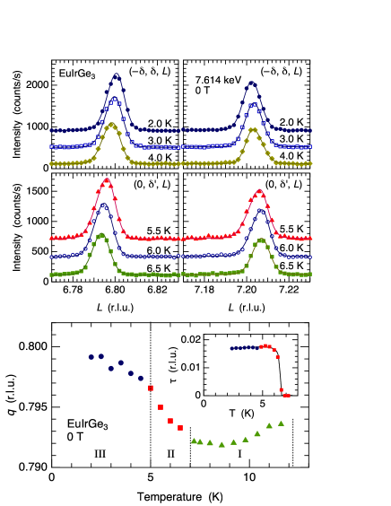
EuIrGe3, with the BaNiSn3-type body-centered tetragonal structure (space group ), is a noncentrosymmetric polar magnet with a four-fold axis and mirror reflection planes including the axis. The point group allows a DM-type antisymmetric exchange interaction. In spite of weak magnetic anisotropy of Eu2+ (, ), EuIrGe3 exhibits successive phase transitions [25, 26, 27]. In a previous paper, we have investigated the magnetic structure of EuIrGe3 in the three successive phases by neutron diffraction and resonant X-ray diffraction (RXD) [28]. It was concluded that a longitudinal sinusoidal structure develops below K with a propagation vector (phase I), which changes to a cycloid with below K (, phase II). Below K, the cycloidal plane rotates by and the vector changes to (, phase III). Here, the magnetic moment of Eu on the th lattice point at is generally expressed as
| (1) |
where represents the Fourier component of the magnetic structure. The magnetic structure of EuIrGe3 is expressed by in phase I, in phase II, and in phase III, where the sign of represents the sense of rotation. Since the vector of the antisymmetric exchange interaction is perpendicular to the mirror plane, on which the vector of EuIrGe3 lies, a unique sense of cycloidal rotation should be selected [29]. However, the sign of remains indeterminate in phases II and III.
In this paper, we report the helicity selection of the cycloid in EuIrGe3, which has been clarified by RXD using circularly polarized beam. We also study the cycloidal domain selection in magnetic fields applied along [100] and [110] directions and show that the cycloidal plane prefers to be perpendicular to the magnetic field, which is equivalent to the condition, and the transverse conical state is realized.
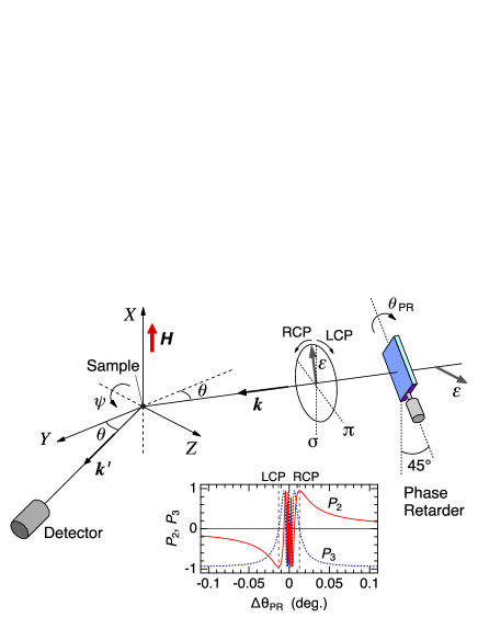
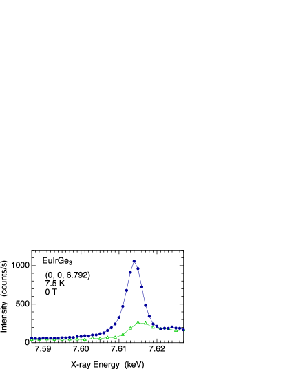
A single crystal of EuIrGe3 was prepared by the In-flux method as described in Ref. 26. The electrical resistivity, specific heat, magnetic susceptibility, and magnetization have already been reported, except for the physical properties in magnetic fields along the [110] axis [25, 26]. RXD experiment was performed at BL-3A of the Photon Factory, KEK, Japan, using the same sample as in Ref. 28. The scattering geometry is shown in the supplemental material (SM) [30]. Magnetic field was applied by using a vertical field 8 T superconducting cryomagnet. The sample was mounted on a rotating stage so that we could perform measurements for and by rotating the sample about the axis. We used X-ray energies around the absorption edge of Eu. X-ray energy dependence of a resonant magnetic Bragg peak in phase I at 7.5 K is shown in the SM [30]. Magnetization measurements for were performed by using a Quantum Design SQUID magnetometer.
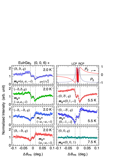
To determine the cycloidal helicity in phases II and III at zero field, we measured the circular-polarization dependence of the intensities of the resonant magnetic Bragg peaks by using a diamond phase-retarder, which is inserted in the incident beam path. By rotating the angle () of the diamond phase plate around the 111 Bragg-angle (), a phase difference occurs between the and components. The right handed circular polarization (RCP) and left handed circular polarization (LCP) is obtained when the phase difference is equal to . The right top panel of Fig. 1 shows the offset-angle () dependence of the polarization state of the incident beam using the Stokes parameters and , where and represent the degree of circular polarization ( for RCP and for LCP) and linear polarization ( for and for ), respectively.
The data at 2.0 K in Fig. 1 are the results for the four resonant Bragg peaks in phase III corresponding to the four cycloidal magnetic domains, which clearly demonstrate the asymmetry with respect to the RCP and LCP incident beams. The solid lines are the calculations for the resonant scattering from cycloidal magnetic structure with a single helicity, i.e., [31, 32, 33, 34, 30], where the Fourier component is shown in each panel. Since the data are well explained by the calculation, the analysis clearly show that the cycloidal structure in phase III has a single helicity. Furthermore, it is noted that the magnetic structures of the four domains perfectly reflect the symmetry of the crystal structure. All the four vectors are related by the rotations and also by the mirror reflections of . This result clearly show that the helicity of the cycloid is uniquely selected by the DM-type antisymmetric interaction.
The same analysis can also be applied to the data at 5.5 K in phase II. It is noted, however, the dependence of the two peaks at becomes flat because of the geometrical reason, where the cycloidal plane lies in the horizontal scattering plane, resulting in and . The data at 7.5 K in phase I with the longitudinal sinusoidal structure is also flat for the same reason.
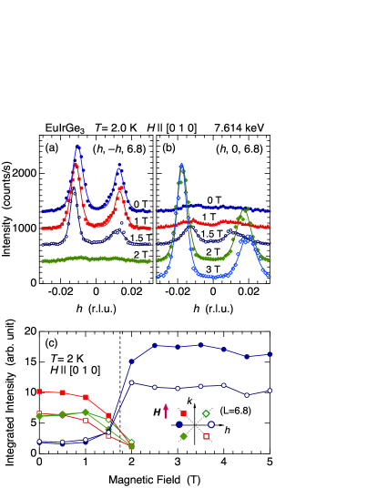
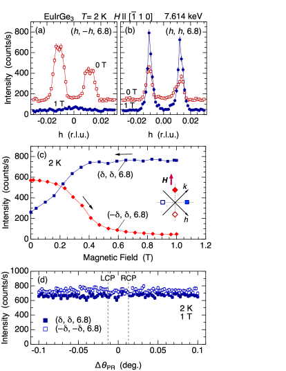
When a magnetic field is applied parallel to the -plane, the magnetic domains are selected so that the cycloidal plane become perpendicular to the applied field. Figures 2(a) and 2(b) show the results of the reciprocal space scans of and , respectively, at several magnetic fields applied along at 2.0 K in the field increasing process. Figure 2(c) shows the magnetic-field dependences of the integrated intensities of the Bragg peaks, including those obtained from the scans. All the four intensities of the Bragg peaks in phase III decrease with increasing the field and disappear at T. On the other hand, the two peaks at , corresponding to the cycloid in phase II, appear at high fields above T. The other two peaks at , which weakly exist at 0 T, also vanishes by applying a field. These results show that a magnetic phase transition takes place from phase III with four domains to phase II with two domains. The two peaks in phase II are at for . This means that the cycloidal plane is in the – plane and the uniform magnetization is induced along the [010] axis. The magnetic phase diagram will be shown later in Fig. 4.
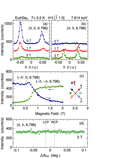
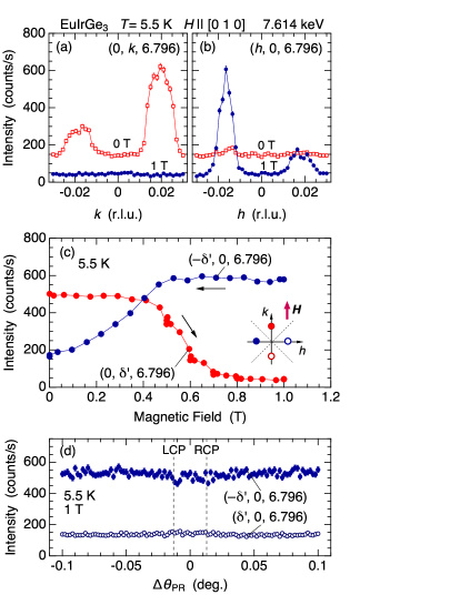
By rotating the sample about the axis by , we performed measurements for . Figure 3(a) and 3(b) show the results of the reciprocal space scans along and at several magnetic fields along at 5.5 K, where the phase II is realized at zero field with . The detailed dependence of below , which was not reported in the previous paper, is summarized in the SM [30]. Figure 3(c) shows the magnetic field dependence of the intensities of the Bragg peaks at and at 5.5 K. The peak intensity of phase II starts to decrease above T, while that of phase III increases. This shows that the magnetic phase transition from phase II to phase III takes place by applying a magnetic field along . Since the Bragg peaks do not appear in the scan, these results again show that the cycloidal plane become perpendicular to the applied field.
When the cycloidal plane lies in the horizontal scattering plane, the dependence of the intensity becomes flat as shown in Fig. 3(d). This is because and are both satisfied. The former condition means that is parallel to the scattering plane. The latter condition, which is specific to the cycloid, is realized when the two orthogonal components of in the scattering plane have a phase difference of . Otherwise, is generally not equal to , and some structure proportional to should arise in the dependence [30].
Normal domain selection occurs for and in phase II and III, respectively. When the field is applied along at 5.5 K in phase II, the intensities of the Bragg peak at vanish above T, whereas those at increase. In the same manner, when the field is applied along at 2.0 K in phase III, the intensities of the Bragg peak at vanish above T, whereas those at increase. These data are summarized in the SM [30]. In these cases, the cycloidal domains are simply selected so that the cycloidal planes are perpendicular to the applied field. The uniform magnetization is induced along the field direction and the transverse conical structure is realized.
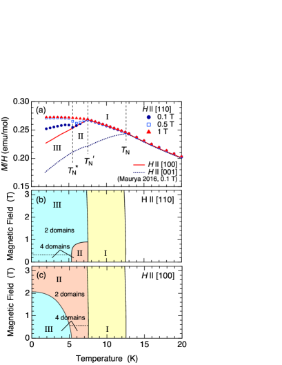
To compare the results obtained from RXD with the bulk property, we measured the dependence of magnetization at several magnetic fields applied along [110], which has not been reported previously. Figure 4(a) shows the dependence of magnetization in the form of for measured at 0.1 T, 0.5 T, and 1.0 T. The results at 0.1 T and 0.5 T clearly exhibit an anomaly at the transition between phase II and III, where the cycloidal plane rotates by . This anomaly is not detected in at 0.1 T for . At 1 T, which is above the critical field of phase II for , only the weak cusp anomaly at is detected. Below , the sinusoidal order of phase I directly changes to the cycloidal order of phase III.
The above results in this work are summarized in the phase diagrams in Figs. 4(b) and 4(c) for and , respectively. The transition at T for reported in Refs. 25 and 26 is the transition from phase III to II, i.e., the rotation of the cycloidal plane, which is accompanied by the domain selection. The boundary below 1 T for in phase II reported in Ref. 25 can be attributed to the anomaly corresponding to the domain selection in phase II. The general response of the cycloidal order below K is that the cycloidal plane prefers to be perpendicular to the external magnetic field. For (), phase II (III) is more stable in magnetic fields, and the cycloidal plane lies within the – plane (– plane) with the uniform magnetization induced along the axis ( axis).
When the cycloidal order is formed, only one mirror plane coinciding with the cycloidal plane remains. Another structure related by the four-fold rotation or by another mirror reflection, which is not preserved in the ordered state, gives the cycloidal structure of another domain. The mirror symmetry is preserved in the transverse conical state when a magnetic field is applied along the direction perpendicular to the mirror plane.
When the transverse conical state is realized in magnetic fields, a lattice modulation with the same propagation vector is allowed by symmetry in such a way that the local polarization proportional to is induced, where represents the translation vector between and along the magnetic propagation vector [35, 36]. In the present case, a lattice modulation can be induced along the direction parallel to the uniform magnetization. This would give rise to a nonresonant scattering with the strong - component. However, no such signal has been detected as shown in Fig. 3(d) and in the SM. Also in Fig. 2(c), the intensities at do not increase above 2 T, suggesting that no such additional scattering occurs. These results indicate that the spin-lattice coupling is tiny, possibly because of the orbital moment of Eu2+ and the metallic nature of this compound. This suggests that the weak magnetic anisotropy could be due to the Fermi surface geometry, which is responsible for the magnetic exchange interaction and definitely reflects the tetragonal symmetry of the lattice[26].
From the phase diagram and the magnetization process, the transverse conical phase is expected to persist up to almost 15 T for -plane. Nontrivial magnetic order such as the skyrmion lattice state is therefore unlikely to occur in this field direction. Magnetic structure study for should be performed in future experiments.
In summary, we performed RXD using circularly polarized beam to clarify the helicity of the cycloidal magnetic structure in phases II and III of EuIrGe3 at zero field. The magnetic structures, including the cycloidal helicity we observed for each magnetic domain, perfectly reflect the symmetry operations of the crystal structure with the point group . This result confirms that the cycloidal helicity is determined by the DM-type antisymmetric exchange interaction.
We also performed RXD to study the magnetic structure in magnetic fields applied along the [100] and [110] directions. When a magnetic field is applied along the [100] direction in Phase III, a phase transition occurs at T, at which the cycloidal plane rotates by to be perpendicular to the applied field. With the uniform component induced along the field direction, a transverse conical order is realized, which is the same structure as in phase II after the domain selection. In the same manner, when a magnetic field is applied along the [110] direction in Phase II, a phase transition occurs at T to the same transverse cycloid as in Phase III after the domain selection.
Acknowledgements.
This work was supported by JSPS Grant-in-Aid for Scientific Research (B) (no. JP20H01854) and by JSPS Grant-in-Aid for Transformative Research Areas (Unveiling, Design, and Development of Asymmetric Quantum Matters, 23A202, no. JP23H04867). The synchrotron experiments were performed under the approval of the Photon Factory Program Advisory Committee (No. 2022G114). MT is supported by JST, the establishment of university fellowships towards the creation of science technology innovation, Grant No. JPMJFS2129.References
- Bogdanov and Hubert [1994] A. Bogdanov and A. Hubert, Thermodynamically stable magnetic vortex states in magnetic crystals, J. Magn. Magn. Mater. 138, 255 (1994).
- Togawa et al. [2016] Y. Togawa, Y. Kousaka, K. Inoue, and J. Kishine, Symmetry, structure, and dynamics of monoaxial chiral magnets, J. Phys. Soc. Jpn. 85, 112001 (2016).
- Tokura and Kanazawa [2021] Y. Tokura and N. Kanazawa, Magnetic skyrmion materials, Chem. Rev. 121, 2857 (2021).
- Dzyaloshinsky [1958] I. Dzyaloshinsky, A thermodynamic theory of ”weak” ferromagnetism of antiferromagnetics, J. Phys. Chem. Solids 4, 241 (1958).
- Moriya [1960] T. Moriya, Anisotropic superexchange interaction and weak ferromagnetism, Phys. Rev. 120, 91 (1960).
- Mühlbauer et al. [2009] S. Mühlbauer, B. Binz, F. Jonietz, C. Pfleiderer, A. Rosch, A. Neubauer, R. Georgii, and P. Böni, Skyrmion lattice in a chiral magnet, Science 323, 915 (2009).
- Kakihana et al. [2018] M. Kakihana, D. Aoki, A. Nakamura, F. Honda, M. Nakashima, Y. Amako, S. Nakamura, T. Sakakibara, M. Hedo, T. Nakama, and Y. Ōnuki, Giant hall resistivity and magnetoresisntance in cubic chiral antiferromagnet EuPtSi, J. Phys. Soc. Jpn. 87, 023701 (2018).
- Kakihana et al. [2019] M. Kakihana, D. Aoki, A. Nakamura, F. Honda, M. Nakashima, Y. Amako, T. Takeuchi, H. Harima, M. Hedo, T. Nakama, and Y. Ōnuki, Unique magnetic phases in the skyrmion lattice and fermi surface properties in cubic chiral antiferromagnet EuPtSi, J. Phys. Soc. Jpn. 88, 094705 (2019).
- Kaneko et al. [2019] K. Kaneko, M. D. Frontzek, M. Matsuda, A. Nakao, K. Munakata, T. Ohhara, M. Kakihana, Y. Haga, M. Hedo, T. Nakama, and Y. Ōnuki, Unique helical magnetic order and field-induced phase in trillium lattice antiferromagnet EuPtSi, J. Phys. Soc. Jpn. 88, 013702 (2019).
- Tabata et al. [2019] C. Tabata, T. Matsumura, H. Nakao, S. Michimura, M. Kakihana, T. Inami, K. Kaneko, M. Hedo, T. Nakama, and Y. Ōnuki, Magnetic field induced triple-q magnetic order in trillium lattice antiferromagnet EuPtSi studied by resonant x-ray scattering, J. Phys. Soc. Jpn. 88, 093704 (2019).
- Homma et al. [2019] Y. Homma, M. Kakihana, Y. Tokunaga, M. Yogi, M. Nakashima, A. Nakamura, Y. Shimizu, D. X. Li, A. Maurya, Y. J. Sato, F. Honda, D. Aoki, Y. Amako, M. Hedo, T. Nakama, and Y. Ōnuki, Magnetic fluctuation and first-order transition in trillium lattice of EuPtSi observed by 151Eu Mössbauer spectroscopy, J. Phys. Soc. Jpn. 88, 094702 (2019).
- Sakakibara et al. [2019] T. Sakakibara, S. Nakamura, S. Kittaka, M. Kakihana, M. Hedo, T. Nakama, and Y. Ōnuki, Fluctuation-induced first-order transition and tricritical point in EuPtSi, J. Phys. Soc. Jpn. 88, 093701 (2019).
- Takeuchi et al. [2019] T. Takeuchi, M. Kakihana, M. Hedo, T. Nakama, and Y. Ōnuki, Magnetic field versus temperature phase diagram for in the trillium lattice antiferromagnet EuPtSi, J. Phys. Soc. Jpn. 88, 053703 (2019).
- Takeuchi et al. [2020] T. Takeuchi, M. Kakihana, M. Hedo, T. Nakama, and Y. Ōnuki, Angle dependence of the magnetic phase diagram in cubic chiral antiferromagnet EuPtSi, J. Phys. Soc. Jpn. 89, 093703 (2020).
- Sakakibara et al. [2021] T. Sakakibara, S. Nakamura, S. Kittaka, M. Kakihana, M. Hedo, T. Nakama, and Y. Ōnuki, Magnetic phase transitions of the skyrmion compound EuPtSi studied by magnetization measurements, J. Phys. Soc. Jpn. 90, 064701 (2021).
- Togawa et al. [2012] Y. Togawa, T. Koyama, K. Takayanagi, S. Mori, Y. Kousaka, J. Akimitsu, S. Nishihara, K. Inoue, A. S. Ovchinnikov, and J. Kishine, Chiral magnetic soliton lattice on a chiral helimagnet, Phys. Rev. Lett. 108, 107202 (2012).
- Honda et al. [2020] T. Honda, Y. Yamasaki, H. Nakao, Y. Murakami, T. Ogura, Y. Kousaka, and J. Akimitsu, Topological metastability supported by thermal fluctuation upon formation of chiral soliton lattice in CrNb3S6, Sci. Rep. 10, 18596 (2020).
- Ohara et al. [2014] S. Ohara, S. Fukuta, K. Ohta, H. Kono, T. Yamashita, Y. Matsumoto, and J. Yamaura, Study of chiral structure and magnetism in heavy-fermion Yb(Ni1-xCux)3Al9, JPS Conf. Proc. 3, 017016 (2014).
- Matsumura et al. [2017] T. Matsumura, Y. Kita, K. Kubo, Y. Yoshikawa, S. Michimura, T. Inami, Y. Kousaka, K. Inoue, and S. Ohara, Chiral soliton lattice formation in monoaxial helimagnet Yb(Ni1-xCux)3Al9, J. Phys. Soc. Jpn. 86, 124702 (2017).
- Ninomiya et al. [2018] H. Ninomiya, T. Sato, K. Inoue, and S. Ohara, Specific heat of the chiral-soliton-lattice phase in Yb(Ni0.94Cu0.06)3Al9, Physica B 536, 654 (2018).
- Aoki et al. [2018] R. Aoki, Y. Togawa, and S. Ohara, Electrical transport properties of micrometer-sized samples of the rare-earth chiral magnet YbNi3Al9, Phys. Rev. B 97, 214414 (2018).
- Tsukagoshi et al. [2023] M. Tsukagoshi, S. Kishida, K. Kurauchi, D. Ito, K. Kubo, T. Matsumura, Y. Ikeda, S. Nakamura, and S. Ohara, Crystal field excitation in the chiral helimagnet YbNi3Al9, Phys. Rev. B 107, 104425 (2023).
- Kézsmárki et al. [2015] I. Kézsmárki, S. Bordács, P. Milde, E. Neuber, L. M. Eng, J. S. White, H. M. Rønnow, C. D. Dewhurst, M. Mochizuki, K. Yanai, H. Nakamura, D. Ehlers, V. Tsurkan, and A. Loidl, Neel-type skyrmion lattice with confined orientation in the polar magnetic semiconductor GaV4S8, Nat. Mater. 14, 1116 (2015).
- Kurumaji et al. [2017] T. Kurumaji, T. Nakajima, V. Ukleev, A. Feoktystov, T. H. Arima, K. Kakurai, and Y. Tokura, Neel-type skyrmion lattice in the tetragonal polar magnet VOSe2O5, Phys. Rev. Lett. 119, 237201 (2017).
- Maurya et al. [2016] A. Maurya, P. Bonville, R. Kulkami, A. Thamizhavel, and S. K. Dhar, Magnetic properties and complex magnetic phase diagram in non-centrosymmetric EuRhGe3 and EuIrGe3 single crystals, J. Magn. Magn. Mater. 401, 823 (2016).
- Kakihana et al. [2017] M. Kakihana, H. Akamine, K. Tomori, K. Nishimura, A. Teruya, A. Nakamura, F. Honda, D. Aoki, M. Nakashima, Y. Amako, K. Matsubayashi, Y. Uwatoko, T. Takeuchi, T. Kida, M. Hagiwara, Y. Haga, E. Yamamoto, H. Harima, M. Hedo, T. Nakama, and Y. Ōnuki, Superconducting, fermi surface, and magnetic properties in SrTGe3 and EuTGe3 (t:transition metal) with the rashba-type tetragonal structure, J. Alloys and Compounds 694, 439 (2017).
- Utsumi et al. [2018] Y. Utsumi, D. Kasinathan, P. Swatek, O. Bednarchuk, D. Kaczorowski, J. M. Ablett, and J.-P. Rueff, Bulk electronic structure of non-centrosymmetric EuTGe3 (T=Co, Ni, Rh, Ir) studied by hard x-ray photoelectron spectroscopy, Phys. Rev. B 97, 115155 (2018).
- Matsumura et al. [2022] T. Matsumura, M. Tsukagoshi, Y. Ueda, N. Higa, A. Nakao, K. Kaneko, M. Kakihana, M. Hedo, T. Nakama, and Y. Ōnuki, Cycloidal magnetic ordering in noncentrosymmetric EuIrGe3, J. Phys. Soc. Jpn. 91, 073703 (2022).
- Yambe and Hayami [2022] R. Yambe and S. Hayami, Effective spin model in momentum space: Toward a systematic understanding of multiple- instability by momentum-resolved anisotropic exchange interactions, Phys. Rev. B 106, 174437 (2022).
- [30] (Supplemental Material) The following pieces of information are provided online. (S1) Scattering configuration of the RXD experiment, the circularly polarized beam obtained by using a phase retarder system, and a formalism of RXD for intensity analysis. (S2) X-ray energy dependence of the resonant magnetic Bragg peak. (S3) Temperature dependence of the -vecotr at zero field. (S4) Normal domain selection for in phase II and (S5) in phase III. .
- Hannon et al. [1988] J. P. Hannon, G. T. Trammell, M. Blume, and D. Gibbs, X-ray resonance exchange scattering, Phys. Rev. Lett. 61, 1245 (1988).
- Lovesey et al. [2005] S. W. Lovesey, E. Balcar, K. S. Knight, and J. Fernández-Rodríguez, Electronic properties of crystalline materials observed in x-ray diffraction, Phys. Rep. 411, 233 (2005).
- Nagao and Igarashi [2005] T. Nagao and J. Igarashi, Resonant x-ray scattering spectra from multipole ordering: Np M4,5 edges in NpO2, Phys. Rev. B 72, 174421 (2005).
- Nagao and Igarashi [2006] T. Nagao and J. I. Igarashi, Electric quadrupole contribution to resonant x-ray scattering: Application to multipole ordering phases in Ce1-xLaxB6, Phys. Rev. B 74, 104404 (2006).
- Katsura et al. [2005] H. Katsura, N. Nagaosa, and A. V. Balatsky, Spin current and magnetoelectric effect in noncollinear magnets, Phys. Rev. Lett. 95, 057205 (2005).
- Arima et al. [2007] T. Arima, Y. Yamasaki, T. Goto, S. Iguchi, K. Ohgushi, S. Miyasaka, and Y. Tokura, Spin-lattice coupling in ferroelectric cpiral magnets: comparison between the cases of (Tb,Dy)MnO3 and CoCr2O4, J. Phys. Soc. Jpn. 76, 023602 (2007).
Supplemental Material
Helicity Selection of the Cycloidal Order in Noncentrosymmetric EuIrGe3
K. Kurauchi, T. Matsumura, M. Tsukagoshi, N. Higa, M. Kakihana, M. Hedo, T. Nakama, and Y. Ōnuki
Resonant X-ray Diffraction Experiment
Figure S1 shows the scattering geometry of our RXD experiment. When the incident X-ray beam from the synchrotron source, which is polarized in the horizontal plane, passes through the diamond phase plate set near a Bragg angle, a phase difference occurs between the and components with respect to the scattering plane tilted by . The phase difference is proportional to , where is the Bragg angle of the phase plate. It is therefore possible to tune the incident linear polarization to right-handed circular polarization (RCP) and left-handed circular polarization (LCP) by manipulating around the Bragg angle . The polarization state of the X-ray after transmitting the phase plate is shown in Fig. S1 as a function of using the Stokes parameters ( for RCP and for LCP) and ( for and for linear polarization) [1]. In the horizontal scattering plane geometry in our experiment, and . Near the beam becomes depolarized. ( for and for linear polarization) is zero in the present setup.
The scattering cross section can be expressed by using the four scattering amplitudes for -, -, -, and - [1].
| (S1) | ||||
The scattering amplitude for the resonant diffraction from a magnetic ordered structure is calculated by
| (S2) | ||||
| (S3) |
where represents the magnetic dipole structure factor for the scattering vector , the magnetic dipole moment located at , and the spectral function of the resonance [2,3]. The energy spectrum of the resonant peak is shown in Fig. S2.
By assuming a model magnetic structure, we can compare the calculated cross section with the experimental dependence of the intensity, which can often be a powerful tool to determine the magnetic structure and the helicity of the spiral orderings. With respect to the scattering from magnetic dipole orderings, vanishes. The asymmetric dependence due to the term arises from the interference between and , which changes its sign when the helicity of the spiral is reversed.
Temperature dependence of at zero field
The detailed dependence of the value of the peak position at in phase I, in phase II, and in phase III, is shown in Fig. S3. The cycloidal pitch along the axis is given by . In our previous paper [4], only the dependence in phase I was reported. The dependence of the peak profiles along the direction around and 7.2 in reciprocal space, as shown in the upper panels, clearly shows that the value increases with decreasing temperature. It seems to approach 0.8 at the lowest temperature.
Normal domain selection in phase II and III
When the external magnetic field is applied along [010] in phase II at 5.5 K, or along [110] in phase III at 2 K, normal domain selection occurs without changing the order parameter. Figures S4(a) and S4(b) show the peak profiles of the and scans, respectively, for at 5.5 K in phase II. The peak existing at 0 T vanishes at 1 T and the peak develops, resulting in the condition. The field dependences of the intensity of these peaks are shown in Fig. S4(c). The boundary of the domain selection in the field increasing process is T, which is shown by the dotted line in Fig. 4(c) in the main text. With respect to at 2 K in phase III, the results are shown in Figs. S5(a), S5(b), and S5(c), and the boundary of the domain selection is shown by the dotted line in Fig. 4(b) in the main text.
The dependences of the Bragg-peak intensity after the domain selection is shown in Fig. S4(d) for the peak and in Fig. S5(d) for the peak. The results are completely flat in both cases, indicating that the Fourier component is in the horizontal scattering plane and vanishes. There is no contribution from the term. Since , the term also vanishes. These results imply that the transverse conical state is realized with the cycloidal plane being perpendicular to the field and the uniform magnetization induced along the field direction. The flat data also show that no Thomson scattering from lattice modulation is induced, which is allowed by symmetry consideration as discussed in the main text. If the Thomson scattering exists, it would give rise to a - scattering and the increase in intensity at half of the LCP and RCP positions.
Flat dependence after domain selection
The scattering-amplitude components in Eq. (S2) are written as
| (S4) | ||||
| (S5) | ||||
| (S6) | ||||
| (S7) |
where , , and represent the (), (), and () component, respectively, of () in Fig. S1. The spectral function was omitted. Since , the term in Eq. (S1) is proportional only to . After the cycloidal domain is selected by the external magnetic field, the magnetic moments lie in the -scattering plane. Consequently, the term vanishes because (). With respect to the term, it is usually expected to remain because is generally not equal to unless the scattering vector (-axis) is parallel to , which is realized in phase I (see the data at 7.5 K in Fig. 1 in the main text). In the present case for the cycloidal order lying in the scattering plane after the domain selection, the two orthogonal components of and have a phase difference of . Therefore, a special condition of is realized even when is not parallel to the scattering vector. Consequently, the term also vanishes.
references
-
[1]
S. W. Lovesey and S. P. Collins, X-ray Scattering and Absorption by Magnetic Materials (Oxford, 1996).
-
[2]
T. Nagao and J. Igarashi, Phys. Rev. B 72, 174421 (2005).
-
[3]
T. Nagao and J. I. Igarashi, Phys. Rev. B 74, 104404 (2006).
-
[4]
T. Matsumura, M. Tsukagoshi, Y. Ueda, N. Higa, A. Nakao, K. Kaneko, M. Kakihana, M. Hedo, T. Nakama, and Y. Ōnuki, J. Phys. Soc. Jpn. 91, 073703 (2022).