Accessible Robot Control in Mixed Reality
Abstract
A novel method to control the Spot robot of Boston Dynamics by Hololens 2 is proposed. This method is mainly designed for people with physical disabilities, users can control the robot’s movement and robot arm without using their hands. The eye gaze tracking and head motion tracking technologies of Hololens 2 are utilized for sending control commands. The movement of the robot would follow the eye gaze and the robot arm would mimic the pose of the user’s head. Through our experiment, our method is comparable with the traditional control method by joystick in both time efficiency and user experience. Demo can be found on our project webpage: https://zhangganlin.github.io/Holo-Spot-Page/index.html
1 Introduction
Over the years, technology has evolved at an ever-increasing rate, affecting all aspects of social life. Following the prominence of disability awareness, developments in the technology world are empowering disabled people by creating better working platforms.
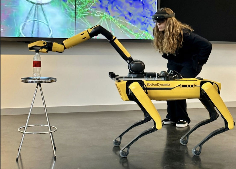
Here, we turn our attention to accessible robot control, as shown in Figure 1. Controlling a robot can become quite a challenge for people with physical disabilities. Using a traditional robot controller is often not an option for them. We have tried to put this problem in the context of mixed reality and come up with solutions that provide a smooth and accessible user experience for people with disabilities. We want to leverage the power of mixed reality and HoloLens2 to develop accessible human-computer interfaces to control or interact with robots.
This project aims to help people with arm or hand amputation to operate the Boston Dynamics Spot robot using HoloLens2. More specifically, we plan to design and implement a pipeline that enables people to move the robot, control the robot arm, and grasp items by eye tracking, head motion and voice control.
Our main contributions include,
-
1.
Figuring out user requirements and designing a system based on them.
-
2.
Implementing and deploying a HoloLens2 application that enables users to control the Boston Dynamics Spot robot using only eye tracking, head movements, and voice control.
-
3.
Conduct initial user study experiments to test the effectiveness of the product.
The rest of this report is structured as follows. In Section 2, we review some related work focusing on the application of mixed reality in robot control. In Section 3, we illustrate our system design at a macro level, describing the workflow of the system and the functionality implemented. Section 4 describes the technical implementation details on both HoloLens and Spot (ROS) sides. For evaluation purposes, we conducted user study experiments, the results of which are documented in Section 5. In Section 6, we provide a summary and suggest possible future improvements.
2 Related Works
The use of mixed reality to control robots to complete tasks is a recent research direction that has emerged. Previous works [4][10][11] utilize mixed reality devices to control the robotic arm. [16] applies the mixed reality to the mobile robot for path planning. However, none of these works is amputation friendly, which means hand gesture is required to control the robot. Compared to these works, [7] combines hand gestures and eye detection to select the object more precisely, [6] utilizes the head position or gesture pointing in combination with speech to control the robot arm. But none of these works is tailored for the mobile robot, and hand operation has not been completely replaced.
3 System Design
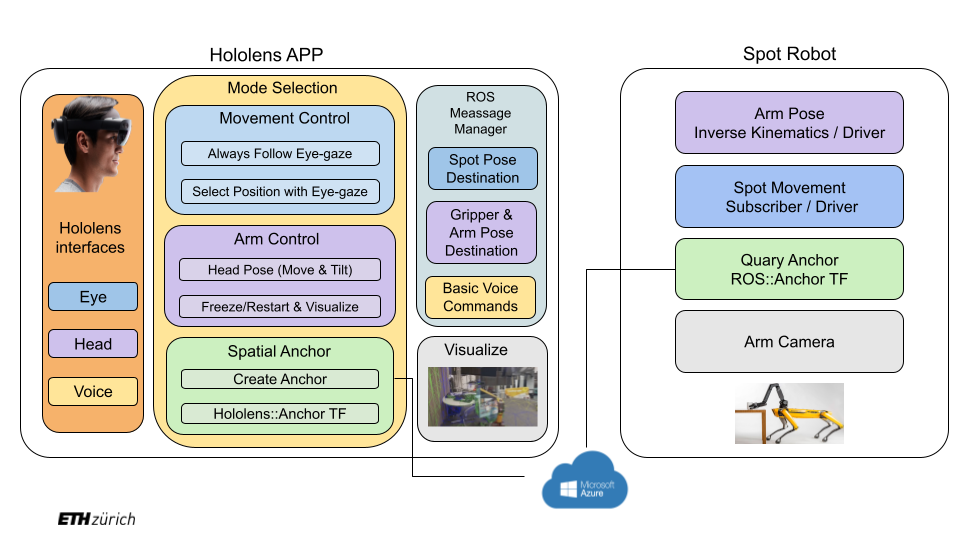
Our system design graph is Figure 2. The whole system is divided into two parts: the Hololens App developed with unity and the ROS code on the Spot Robot. The Azure spatial anchor is used for the co-localization between Hololens and the Spot robot. Aiming to help people with amputation, the whole app is controlled by eye gaze, head motion, and voice commands. Users can use voice to give simple commands like sit and stand. In the meantime, voice commands can be used to switch the robot to different modes, including moving the robot, controlling the robot arm/hand, and creating spatial anchors. For different modes, users will utilize the eye gaze and head motion to control the Spot robot. During the process, Hololens keeps sending ROS messages to the Spot robot, these messages contain important information like position destination and arm pose destination. The robot always listens to the messages, it would query the spatial anchor, perform necessary calculations and do the actions.
3.1 Functions
Our functions can be summarized into robot body control and robot arm control. All the functions are driven by voice commands. Users can switch to a certain mode and activate/terminate the current mode.
3.1.1 Basic Voice Commands
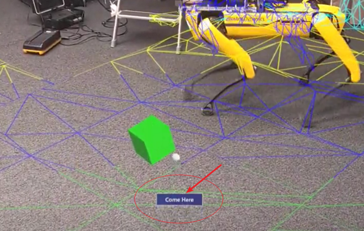
We have over 10 basic voice commands that users can use to carry out some basic actions. These include sit, stand, power on, power off, claim, release, self right, roll over left, roll over right, spin left, and spin right. Their meanings are straightforward, the robot would carry out these actions as soon as it receives the command. A special command is come here, by saying this the robot would go to the position of the Hololens.
3.1.2 Follow Mode
This mode is selected by saying follow mode. When follow mode is activated, the Spot robot will always follow users’ eye gaze. To make it more clear, we use a sphere cursor to let the users know their current eye gaze position.
3.1.3 Select Mode
This mode is selected by saying select mode. When users are in the select mode, they need to first select a position by saying select item, then a white cube would show at the select position. The Spot robot will go directly to the currently selected position when the select mode is activated. Users can stop the robot by saying terminate, and the robot will continue heading to the selected position when the users say activate again. At any time, only one selected position can exist.
3.1.4 Arm Mode
This mode is selected by saying arm mode. Users can say activate to start this mode, and the robot arm will follow the users’ head movement. A live video stream of the robot’s hand view can be opened/closed by saying visualize on/off. The picture will pop up at the top right corner. The arm can be frozen at a certain pose by terminate. Users can move to a new position, re-activate arm mode, and the arm will start at the previous position. This will make control much easier. By saying rotate hand/stop rotate hand, users can start/stop rotating the gripper. The gripper will rotate to the left/right if users tilt their heads to the left/right. Users can say grasp to open the gripper and say it again to close the gripper.
4 System Implementation
4.1 Hololens
4.1.1 Communication
On the Hololens side, we use the ROS TCP Connector package [14] from Unity for the communication between Unity [5] and ROS [12]. For Follow Mode and Arm Mode which require sending messages continuously, we check if the time elapsed is longer than the time frequency we set, and only publish messages when the condition is true. We use the same message type and different topic names for different modes. Although the message types are the same, the concrete information is different for different modes. When the application is launched, we will register all the topics.
4.1.2 Mode Switching
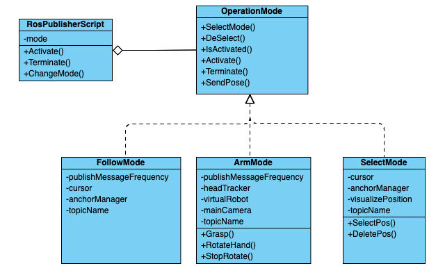
Since we have different modes for the user to control the robot, and GUI is not available for our target user, there are too many voice commands if we naively assign one command for each mode. It is necessary to reuse the voice command for different modes. Besides, some voice commands are tailored for a specific mode. For example, grasp, rotate hand, and stop rotate hand are only callable only when the current mode is arm mode. And select item, delete selection commands are only available when the current mode is the select mode. Therefore, in order to achieve these requirements and encapsulate varying behavior for the same object, we use state pattern [3] as shown in the class diagram Figure 3. We design an interface called OperationMode, this object is held by RosPublisherScript as an attribute. Once the ChangeMode function is called, a specific mode (one of follow mode, arm mode, or select mode) is assigned to this attribute. And the Activate() and Terminate() functions will call the member functions self.mode.Activate(), self.mode.Terminate() respectively, to achieve different behavior for different modes.
Another important issue is that the Spot robot receives different message formats for different modes. For example, the follow mode consecutively sends the target position to the robot, the select mode intermittently sends the target position, and the arm mode consecutively sends the head pose to the robot. Also, for position and rotation, the coordinate transformations between the Unity frame and the Azure Anchor frame are different. Therefore, we implement different SendPose() methods for different modes, and this function is called by the RosPublisherScript::Update() method.
For the mode-specified commands, we use a flag to record whether the current mode is selected, and only operate the command when the current mode is selected. In order to create an object instance of different modes and change public attributes more conveniently, we create game objects for each mode and attach the mode classes as scripts.
4.1.3 Eye-gaze Tracking
Since the application uses eye gaze to control the robot’s motion, eye-gaze tracking is significant. The eye gazing ray is obtained through the eye gaze API of HoloLens2, and we directly set the eye cursor position to the intersection between the eye ray and the world mesh constructed by the Hololens2. A challenge encountered in this step is that the collider of the cursor is enabled. Initially, we move the cursor to the intersection point between the eye gaze and the mesh in the EyeGazeCursor::Update() function for every frame. However, the eye gaze intersection interface provided by the MRTK [9] takes all game objects into account. When the cursor is moved to the intersection point, the eye gaze intersects with the cursor, and this point is mistakenly used by the MRTK as a new hit point to move the cursor. As a result, the cursor will directly move to the camera. We solved this problem by turning off the box collider of the eye gaze cursor. As shown in Figure 3, the cursor is held by FollowMode and SelectMode as an attribute, which enables these two modes to send messages depending on the cursor position.
4.1.4 Head Tracking
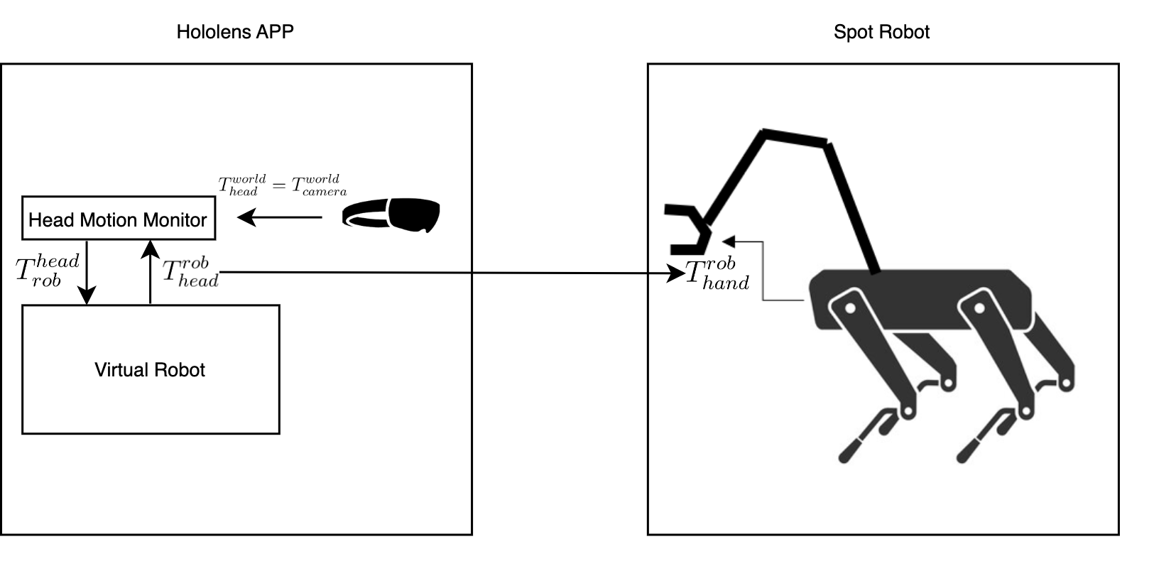
Head tracking is the most challenging part of the project since we need to handle many coordinate transformations. Since our goal is to let the robot arm mimic the behavior of the human head, a local coordinate of the robot hand in the robot frame needs to be specified. As shown in Figure 4, we implement a head motion monitor and a virtual robot to extract the head motion and compute the local coordinate. We denote the transformation of the object under object ’s local frame as , where and represent position and rotation respectively. Then we have:
| (1) | ||||
The initial hand position can be hard-coded as the offset of the real robot and the initial position of the virtual robot could be calculated as:
| (2) |
After initialization, once the user is moving, the head location can be directly assigned as the global coordinate of the camera, and we can update using equation 1. Instead of explicitly calculating the head position in the virtual robot’s frame, we create a head tracker game object as a child of the virtual robot object, and we can directly get the transformation using headTracker.transform.localPosition.
An important issue for arms control is that the user cannot readily watch the target object when she (or he) is moving her head. To solve this problem, we store the local transformation of the virtual robot under the camera (head) frame and use this transformation to initialize the virtual robot’s position when the arm control is activated again. Another issue is that the gripper angle may not be perfect for grasping items. Therefore, we enable the user to continuously rotate the gripper by tilting the head to adjust the angle.
4.1.5 Spatial Anchor
The Azure Spatial Anchor can be used to co-localize Hololens and the Spot robot, in order to use it we used the Microsoft Azure Spatial Anchors package. In the Azure [8] official tutorial, the code for creating anchors is given. When creating anchors, we first check if there are any existing anchors in the desired location, if there are not, we create a new anchor. Every time before sending positions, we transform the position into the anchor’s local space. We could do this directly by calling anchor.transform.InverseTransformPoint(). Because of the different coordinate systems used in Unity [5] and Anchor [8], we need to manually change the position we send from (x,y,z) to (z,-x,y).
4.1.6 User Interface
Voice Control.
Voice commands provide simple and flexible ways to interact with the environment. To enable it in our application, we utilize the speech input system in MRTK [9] together with the SpeechInputHandler component. Different voice commands are specified in the MixedRealityToolkit object Input Speech settings. Detailed response functions are set in the SpeechInputHandler bounded to objects that handle the activities. For example, as the RosPublisher object handles robot-related commands, one SpeechInputHandler component is added there, and corresponding reacting functions are specified. To ensure that the voice recognition module works properly, a speech confirmation tooltip prefab is enabled. When a voice command is detected, a small box with the corresponding recognized command pops up in the view as shown in Figure 5.
Video Live Stream.
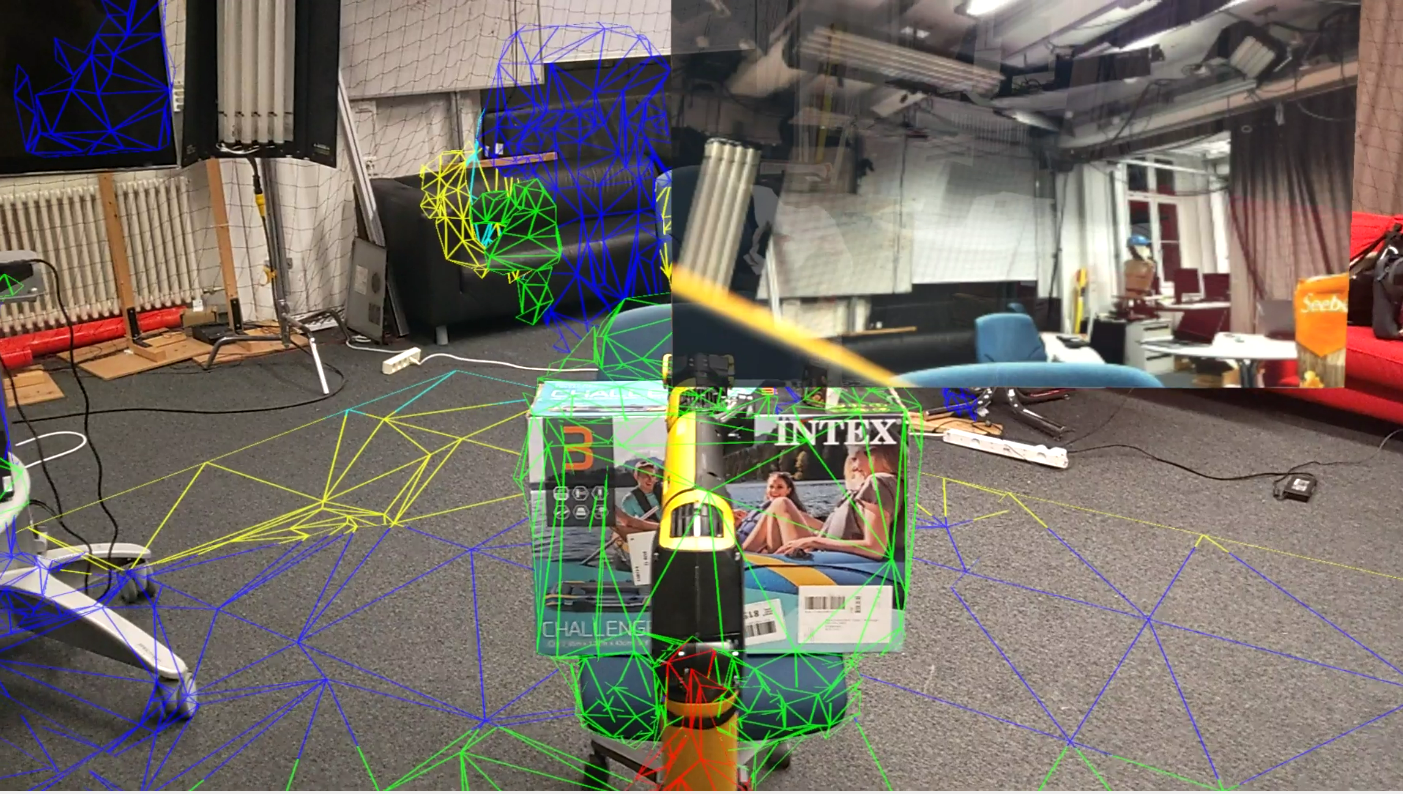
When users operate the robot arm, sometime the view of the users would be blocked by the arm itself. To help the users have better views, a video live stream is added in Hololens, which is placed in an image plane, in front of the user, as shown in Figure 6. The video is captured by the camera which is mounted on the gripper of the robot arm. But since the arm will rotate according to the head’s motion, if we just simply fix the orientation of the image plane, the video itself would also rotate, which is hard for the user to watch. To avoid this problem, we subscribe to the orientation angle of the gripper by the ROS topic joint_states, and also apply this orientation change to the image plane, this way, even if the camera is rotated, the video is always adjusted to make sure to keep the right angle.
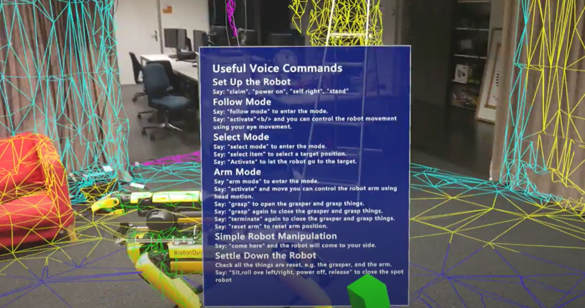
Help Panel.
The prefab for the help panel is from the MRTK Foundation package. On the panel, useful voice commands are listed as shown in Figure 7. The panel will pop up and disappear according to voice commands. Besides, it locates at position relative to the camera position whenever it is enabled. It does not change position according to user movement. It gives users necessary prompts when they interact with the Spot robot using HoloLens2.
4.2 Spot Robot and ROS
4.2.1 Spatial Anchor Localization
To co-localize Hololens and Spot robot, Spatial Anchor from Microsoft Azure [8] is used, as described in Section 4.1.5. The Spot robot needs to recognize the coordinate frame of the Spatial Anchor, which is achieved by the Spatial Anchor ROS package from Microsoft [1]. Basically, we use the visual information collected by the camera of the Spot robot, and get the Spatial Anchor ID passed by the Hololens via ROS topic, then query the Anchor ID by Microsoft Azure. The coordinate frame of the certain Spatial Anchor is then added to the frame transformation tree of ROS.
4.2.2 Frame Transformation
Since we have several coordinate frames (Unity [5], Spatial Anchor [8], and ROS [12]), all of them are represented in different coordinate systems, i.e. Unity uses left-hand y-up system, Spatial Anchor uses right-hand y-up system, and ROS use right-hand z-up system. To handle these different coordinate systems, we adjust the coordinate manually, by the ROS package spot-mr-core [15] to transform all these three coordinate systems to the right-hand z-up systems, before using the tf package from ROS to do the frame transformation. This way, the destination coordinates sent by Hololens can be used directly in the ROS coordinate system.
4.2.3 Spot Robot Movement
For the robot movement, after we get the destination coordinate in the robot’s body frame by the frame transformation, the robot will rotate angle along the -axis to turn to the target direction and go to the target position simultaneously.
| (3) | ||||
The ROS topic /spot/go_to_pose would be used to publish the desired pose in the robot’s body frame: desired position and desired orientation
4.2.4 Spot Robot Driver
We use the Spot Robot ROS Driver [13] to wrap the original Spot Robot Driver [2] into ROS. We use the ROS topic /spot/go_to_pose to control the movement of the robot, the ROS service /spot/gripper_pos to control the pose of the robot arm, and the ROS service /spot/gripper_angle_open to open/close the gripper.
However, the original ROS service /spot/gripper_pos cannot adjust the operational time, it is fixed to 5 seconds to operate all the commands, which is too slow for our task, i.e. our update rate is 0.5 seconds. To overcome this problem, we adjust the driver and pass one more parameter to describe how long to operate the command. This way, the robot arm can follow the user’s command fluently.
5 User Study
To evaluate the effectiveness of our product, we conduct a user study. In this stage, we assess users’ feelings when interacting with the application from usability, usefulness, and emotional aspects. The user experience is analyzed with quantitative and qualitative measurements. The experiment settings and user study results are described below.
5.1 Experiment Settings
Our goal is to test the two main functions of the application, namely using HoloLens2’s eye tracking module to control robot walking and utilizing its head motion capture function for arm manipulation 111The gripping function was not tested here because the Spot robot’s gripper in the CVG lab was damaged..
The user study contains three parts, preparation, experiment conduct, and user feedback. In the preparation phase, we demonstrated to participants how to use the controller and Hololens 2 to control the robot. In addition, we gave participants 10 minutes per device to familiarize themselves with specific operations.
In the experiment phase, we asked participants to complete the following two tasks with the controller and HoloLens 2, and recorded the time spent. The two scenarios are,
-
1.
Walking the robot from a specified starting point to a target location,
-
2.
Asking the user to touch a bottle on a table with the robot arm.
Finally, we distributed questionnaires to participants and got their subjective evaluations of our application.
Evaluation Metrics
Task performance and subjective ratings are considered quantitative metrics here. We use the task completion time to reflect task performance and it is an objective measurement. The participants’ ratings can give a highly-interpretational subjective reflection on their real feelings. Besides, qualitative assessments are included. We pay attention to the verbal feedback from users during experiments, and also ask them in the questionnaire about their psychological feelings, suggestions, and their thoughts on the accessible robot control topic.
Questionnaire
The questionnaire contains 8 questions,
-
1.
Have you played with the Spot robot and/or HoloLens before? (1. Spot robot; 2. HoloLens; 3. None of them)
-
2.
How would you control the Spot robot if you have hand disabilities? (Open question)
-
3.
How would you rate your experience of robot movement using HoloLens follow mode? (Rate from 1 to 5; 1 means very bad, and 5 means very good)
-
4.
How would you rate your experience of robot movement using a controller? (Rate from 1 to 5; 1 means very bad, and 5 means very good)
-
5.
How would you rate your experience of robot arm movement using HoloLens arm mode? (Rate from 1 to 5; 1 means very bad, and 5 means very good)
-
6.
How would you rate your experience of robot arm movement using a controller? (Rate from 1 to 5; 1 means very bad, and 5 means very good)
-
7.
Do you think controlling via Hololens by our method is easier than the way you proposed? (1. Yes; 2. No)
-
8.
Any further suggestions for our application improvement? (Open question)
They are distributed to users in Google Form format.
5.2 Results
| Average Time | Average Score | |||
|---|---|---|---|---|
| Controller | HoloLens2 | Controller | HoloLens2 | |
| Senario 1 | 15.3s | 30.8s | 5.0/5.0 | 4.3/5.0 |
| Senario 2 | 18.7s | 28.2s | 4.4/5.0 | 4.0/5.0 |
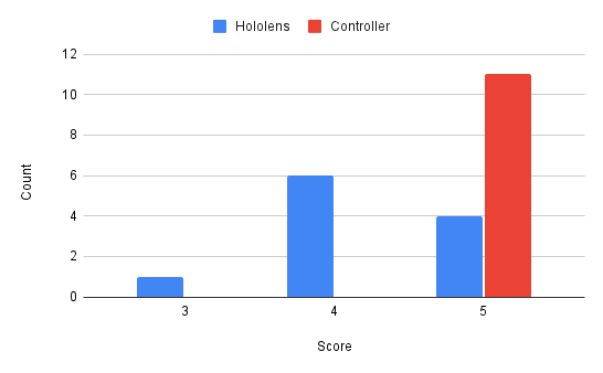
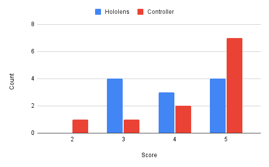
So far, eleven users have taken part in our user study. Two of them have exposure to HoloLens, while the remaining nine participants have no previous experience with the two devices. Their average task performance and subjective ratings are shown in Table 1 and detailed quantitative distributions are illustrated in Figure 8. Compared to the controller, users spend twice more time using HoloLens2 to move the robot to a specific location. Besides, it takes ten more seconds to operate the robot arm to touch the target item. Before making any conclusion, we need to clarify that our purpose is not to surpass the controller performance but take it as a baseline to reflect the smoothness and convenience of operating the robot using our developed application. Generally speaking, the controller provides a smoother experience, but the Hololens2 operation is also acceptable. Operating the robot arm using Hololens2 turns out to provide users with a comparable experience as a controller.
The participants give us their solutions to accessible robot control in their responses to the questionnaire. Besides voice control and eye tracking we’ve applied in this project, they propose using body pose, foot movement, and EEG to operate the robot. 54.5% (six persons) think their solutions perform similarly to ours and 45.5% (five persons) consider our solution better.
The users have provided us with valuable suggestions. For example, apply some safe collision avoidance strategies for the robot arm, and reduce the number of commands needed to switch among modes.
6 Future Work
In conclusion, our group has successfully designed, implemented, and deployed a HoloLens application that allows users to control the Spot robot using only eye gazing, head motion and voice control. It provides a solution for accessible robot control using mixed reality.
Considering the limited time, our deployed product is a preliminary prototype, and there is still room for further improvements. One potential future work is to extend the current working scenario by adding more modes. For example, implement a mirror mode, which allows the robot to walk following the user’s body movement. Another idea is to utilize computer vision to Besides, the user interface design can take advantage of the state pattern and show mode-specific information. Another essential topic relates to user experience concerns. We would like to involve more people in our future user study experiments. So far, our experiment participants are constrained to students. But it is necessary to consider people with different ages, genders, occupations, and physical disabilities to obtain representative results. Based on their feedback, we could understand the user expectation better and improve our application.
7 Acknowledgement
We thank our supervisor Eric Vollenweider for the help and tons of useful advice for this project. We also thank Boyang Sun for the support for the usage of the Spot robot from CVG lab.
References
- [1] Jeff Delmerico, Helen Oleynikova, Eric Vollenweider, Chris Suarez, and Blake Anderson. Azure spatial anchors ros. https://github.com/microsoft/azure_spatial_anchors_ros, 2022.
- [2] Boston Dynamics. spot-sdk. https://github.com/boston-dynamics/spot-sdk, 2022.
- [3] Paul Dyson and Bruce Anderson. State patterns. Pattern languages of program design, 3:125–142, 1996.
- [4] Samir Yitzhak Gadre, Eric Rosen, Gary Chien, Elizabeth Phillips, Stefanie Tellex, and George Konidaris. End-user robot programming using mixed reality. In 2019 International conference on robotics and automation (ICRA), pages 2707–2713. IEEE, 2019.
- [5] John K Haas. A history of the unity game engine. 2014.
- [6] Dennis Krupke, Frank Steinicke, Paul Lubos, Yannick Jonetzko, Michael Görner, and Jianwei Zhang. Comparison of multimodal heading and pointing gestures for co-located mixed reality human-robot interaction. In 2018 IEEE/RSJ International Conference on Intelligent Robots and Systems (IROS), pages 1–9. IEEE, 2018.
- [7] Mikko Kytö, Barrett Ens, Thammathip Piumsomboon, Gun A Lee, and Mark Billinghurst. Pinpointing: Precise head-and eye-based target selection for augmented reality. In Proceedings of the 2018 CHI Conference on Human Factors in Computing Systems, pages 1–14, 2018.
- [8] Microsoft. Azure spatial anchors. https://learn.microsoft.com/en-us/windows/mixed-reality/design/spatial-anchors.
- [9] Microsoft. Mixed reality toolkit. https://learn.microsoft.com/en-us/windows/mixed-reality/mrtk-unity/mrtk2, 2022.
- [10] João Neves, Diogo Serrario, and J Norberto Pires. Application of mixed reality in robot manipulator programming. Industrial Robot: An International Journal, 2018.
- [11] Mikhail Ostanin and Alexandr Klimchik. Interactive robot programing using mixed reality. IFAC-PapersOnLine, 51(22):50–55, 2018.
- [12] Stanford Artificial Intelligence Laboratory et al. Robotic operating system.
- [13] Michal Staniaszek. spot-mr-core. https://github.com/heuristicus/spot_ros, 2022.
- [14] Unity Technologies. Ros tcp connector. https://github.com/Unity-Technologies/ROS-TCP-Connector, 2022.
- [15] Eric Vollenweider. spot-mr-core. https://github.com/EricVoll/spot-mr-core, 2022.
- [16] Mulun Wu, Shi-Lu Dai, and Chenguang Yang. Mixed reality enhanced user interactive path planning for omnidirectional mobile robot. Applied Sciences, 10(3):1135, 2020.