These authors contributed equally to this work.]
These authors contributed equally to this work.]
Tunable mechanically-induced hysteresis in suspended Josephson junctions
Abstract
The coupling of superconducting systems to mechanical resonators is an emerging field, with wide reaching implications including high precision sensing and metrology. Experimental signatures of this coupling have so far been small, seldom and often reliant on high frequency AC electronics. To overcome this limitation, in this work we consider a mechanical resonator suspended between two superconducting contacts to form a suspended Josephson junction in which the electronic normal- and super-currents can be coupled to mechanical motion via the Lorentz force due to an external magnetic field. We show both analytically and numerically that this electro-mechanical coupling produces unprecedented mechanically-induced hysteresis loops in the junction’s DC I-V characteristic. Firstly, we unveil how this new hysteresis may be exploited to access a huge mechanically-induced Shapiro-like voltage plateau, extending over a current range comparable with the junction’s critical current. We then investigate a sudden mechanically-induced retrapping that occurs at strong coupling. Our analytical treatment provides a clear explanation for the effects above and allows us to derive simple relationships between the features in the DC I-V characteristic and the resonance frequency and quality factor of the mechanical resonator. We stress that our setup requires only DC current bias and voltage measurements, allowing the activation and detection of high-frequency mechanical oscillations in state of the art devices and without the need of any AC equipment.
pacs:
74.50.+rI Introduction
The recent progress of nanofabrication techniques has led to a rapid expansion of the nano-electromechanical systems (NEMS) industry, spurring the creation of nano-scale actuators dong , motors kim and switches jang . Various groups have used carbon allotropes such as diamond gaidarzhy , carbon nanotubes laird ; moser and graphene bunch ; chen to create mechanical resonators with resonance frequencies in the GHz range laird and quality factors greater than moser . These sharp, high frequency resonators find applications in attogram mass measurement ilic ; li , single molecule detection naik and high density data storage despont . Besides the plethora of promising applications, NEMS also provide a playground to explore the fundamental properties of mesoscopic devices bachtold , including the quantization of heat transfer schwab and the cooling of macroscopic oscillators to their quantum mechanical ground state sonne ; sonne2 . An area yet to be thoroughly explored is the interplay between electronic and mechanical degrees of freedom in superconducting systems haque ; kretinin ; marchenkov ; schneider ; etakiSSO ; Khosla . Experimental signatures of this interplay have so far been small, seldom and often reliant on high frequency AC electronics.
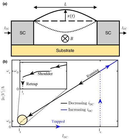
To address this challenge and unveil electro-mechanical effects in superconducting NEMS under controllable conditions we recently considered a simple setup constituted by a mechanical oscillator suspended between two superconducting contacts, forming a suspended electro-mechanical Josephson junction sonne ; sonne2 ; mcdermott , as illustrated in Fig. 1(a). Josephson predicted that if two superconductors are weakly linked, a supercurrent will flow between them, where is the critical current and is the gauge-invariant superconducting phase difference between the two electrodes josephson . He further predicted that a voltage V across the junction (either externally imposed by a bias or spontaneously developed by the junction dynamics) would cause the phase to evolve as , thus resulting in a high frequency AC supercurrent. Due to the tiny impedance of the Josephson junction it is very difficult to experimentally maintain a constant voltage bias, and invariably the device will operate in a current-bias mode likharev . With this in mind, we propose a simple setup constituted by a DC current-biased suspended Josephson junction where the coupling between the electronic currents in the weak link and the out-of-plane displacement of the resonator can be controlled by an external in-plane magnetic field via the related Lorentz force. In a first analysis of this setup we have shown theoretically mcdermott that the excitation of mechanical oscillations of frequency in the Josephson weak link results in a Shapiro-like shapiro shoulder at a voltage close to in the DC I-V characteristic (IVC) of a current-biased junction, due to the synchronisation of the oscillating supercurrent and the resonant vibrations (Fig. 1(b)).
In the present theoretical paper we unveil for the first time mechanically-induced hysteresis loops in the DC IVC of a current-biased suspended Josephson junction. By traversing the hysteresis loop, a huge voltage plateau appears with a magnetic-field tunable width that can be larger than half of the critical current. This large feature presents the most convincing signature of coupling between superconductors and mechanical resonators to date, providing an experimental advantage for those characterising nano-resonators and searching for signatures of mechanical resonance. In contrast to conventional Shapiro steps in the IVC induced by external radiation, here they emerge from spontaneously induced oscillations in the coupled junction-oscillator system. Energy-sharing between the two coupled systems leads to a number of discrete transitions between the resistive and superconducting states at critical coupling values. We analyse and predict quantitatively these transitions using an analytical framework and energy considerations. The derived analytical expressions allow one to deduce the mechanical quality factor simply by measuring the critical coupling values.
We stress the simplicity of the proposed setup, requiring only DC current bias and voltage measurements to induce and detect mechanical resonances in the suspended Josephson junction. The critical coupling values can be achieved with moderate magnetic fields and temperatures attainable in a commercial cryostat.
II Model
The set up we consider is depicted in Fig. 1 (a). A Josephson weak-link with resistance and capacitance is biased with a DC current . The weak-link (effectively either one- or two-dimensional in nature) is suspended between two superconducting contacts and acts as a mechanical oscillator with a fundamental flexural mode with displacement amplitude , characterised by an effective mass , length , resonant frequency and quality factor . The coupling between the electronic currents flowing through the weak-link and the oscillations is controlled by an in-plane magnetic field .
The experimentally tunable parameters are the bias current and the magnetic field, which we express in dimensionless form as and respectively. Here is the junction critical current, whilst is the characteristic magnetic field scale of the oscillator. This set of parameters leads to the length scale , that corresponds to the displacement at which the mechanical restoring force equals the Lorentz force . By employing the resistively and capacitively shunted junction (RCSJ) model stewart we recently derived the following system of equations mcdermott for the gauge-invariant superconducting phase difference and the dimensionless oscillator displacement (measured from the DC offset),
| (1) | |||
| (2) |
Here indicates the derivative of with respect to the dimensionless time , and we have defined the dimensionless quantities (the resonant frequency in units of the junction characteristic frequency ) and (related to the Stewart-McCumber parameter ). In the presence of a finite the mechanical Eq. (2) is driven and renormalised by the Lorentz force, whilst the electrical Eq. (1) is the usual RCSJ model with an additional back-action term due to the motion of the weak-link in a magnetic field.
Typical parameters for suspended carbon nanotube systems are peng ; garcia ; huttel ; laird ; moser ; jarillo ; cleuziou ; Mergenthaler , , , , , and , resulting in the derived quantities and . With these parameters the junction operates in the underdamped hysteretic regime () characterised by an essentially constant voltage and normal current likharev . When a finite time-average voltage develops across the underdamped junction it drives an AC electronic supercurrent of frequency through the weak link. This is largely shunted by an AC displacement current due to the oscillating electric fields around the junction, while an essentially constant electronic normal-current accounts for the remaining DC current bias. Thus, in the underdamped regime, even with a DC bias current the weak link supports a time-dependent net electronic (normal and super) current. When the AC supercurrent component has a frequency matching the resonance frequency of the normal mode, mechanical oscillations can be activated and amplified controllably via the Lorentz force due to the in-plane magnetic field mcdermott .
Since typically , the mechanical resonance activation can only occur by exploiting the hysteresis loop indicated in Fig. 1(b). Firstly the running (Ohmic) state is entered by driving , yielding finite voltages corresponding to frequencies greater than (blue line). Then, lower frequencies can be reached by progressively reducing (black line) until mechanical activation occurs at the dimensionless frequency (note that the junction must be suitably underdamped such that retrapping does not occur before resonance is achieved). This mechanical resonance manifests itself as a voltage shoulder in the DC IVC, as discussed in mcdermott . Once the shoulder is entered, reducing further leads to retrapping at , as shown in the inset in Fig. 1(b).
III Weak-Coupling
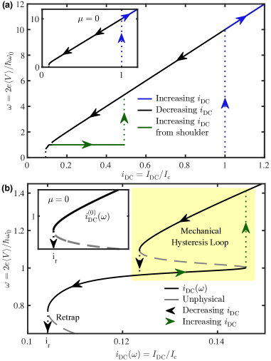
A set of natural questions arises: can one extend the size of the shoulder to enter a full mechanically-induced plateau by increasing once the mechanical resonance is reached? What is the fate of this plateau for larger coupling? To address these questions we first performed a numerical analysis of Eqs. (1) and (2) with finite . The result is staggering: after entering the shoulder in the DC IVC, by increasing one observes a massive mechanically-induced voltage plateau at , with width on the order of half of the junction critical current (continuous green line in Fig. 2(a)). This plateau is reminiscent of the Shapiro steps induced by external radiation, while here the AC signal is provided by the spontaneously induced mechanical vibrations. For small values of the coupling (to be quantified in Sec. IV), the plateau extends until a sudden transition occurs to the Ohmic state (dashed green line in Fig. 2(a)), forming a massive mechanically-induced hysteresis loop in the IVC. This feature is to be contrasted with the IVC of an underdamped junction in the absence of mechanical oscillations (), as shown in the inset in Fig. 2(a).
To understand this behaviour and assess the size of the loop as a function of the coupling strength, we study analytically the relation between and . In order to derive we employ the following ansatzes for the gauge-invariant phase difference and the oscillator displacement in the underdamped regime mcdermott
| (3) | |||
| (4) |
Here parametrises a small mechanically-induced voltage fluctuation, is the oscillator amplitude and is a phase delay. Inserting these ansatzes into the equations of motion (1) and (2) we deduce the current function that is plotted in Fig. 2(b). This is conveniently decomposed as the sum of a -independent smooth profile and a -dependent peak centred around . The uncoupled IV characteristic () is given by
| (5) |
which is plotted in the inset in Fig. 2(b). Regions with (indicated as grey dashed lines) are regarded as unphysical, so that the physical part of this curve ranges from a minimum of corresponding to the uncoupled retrapping frequency (cf. the common result ), to the ohmic behaviour for .
At finite the mechanical peak is manifested as a large resonance centred at in the DC IVC (Fig. 2(b)). The physical portion of this peak () is responsible for the large voltage plateau in Fig. 2(a) that is explored by increasing the current bias (green arrows in Fig. 2(b)). If one increases the current bias past the peak in , to remain in a physical state the system makes a vertical voltage transition to the Ohmic branch (green dotted line), forming the mechanical hysteresis loop highlighted by the yellow box in Fig. 2(b). The shape and width of the mechanically-induced plateau is entirely determined by the function (see full expression in the Supplementary Material). The essential features of the plateau are captured by expanding about . Here the function takes the form of a Fano-resonance
| (6) |
where the Fano-frequency is , the linewidth and . In the limit the Fano formula reduces to the usual Breit-Wigner (Lorentzian) expression. The peak frequency, corresponding to the voltage plateau, is equal to the value which is independent of and extremely close to the bare resonance frequency . The independence of the plateau frequency on is important for metrology applications. The width of the voltage plateau in the DC IVC is determined by the height of the peak
| (7) |
The plateau width thus increases quadratically with until a strong coupling regime is entered, where this analysis breaks down, as detailed below. Analytical insight in the mechanical oscillation amplitude is provided in the Supplementary Material, while here we concentrate on the fate of the IVC in the strong coupling regime.
IV Strong-Coupling
The voltage plateau in our setup emerges from spontaneously induced oscillations in the coupled junction-oscillator system. As such, the electronic and mechanical systems are subject to energy exchange, which can cause mechanically-induced retrapping events in the IVC at large coupling, as illustrated in Fig. 3.
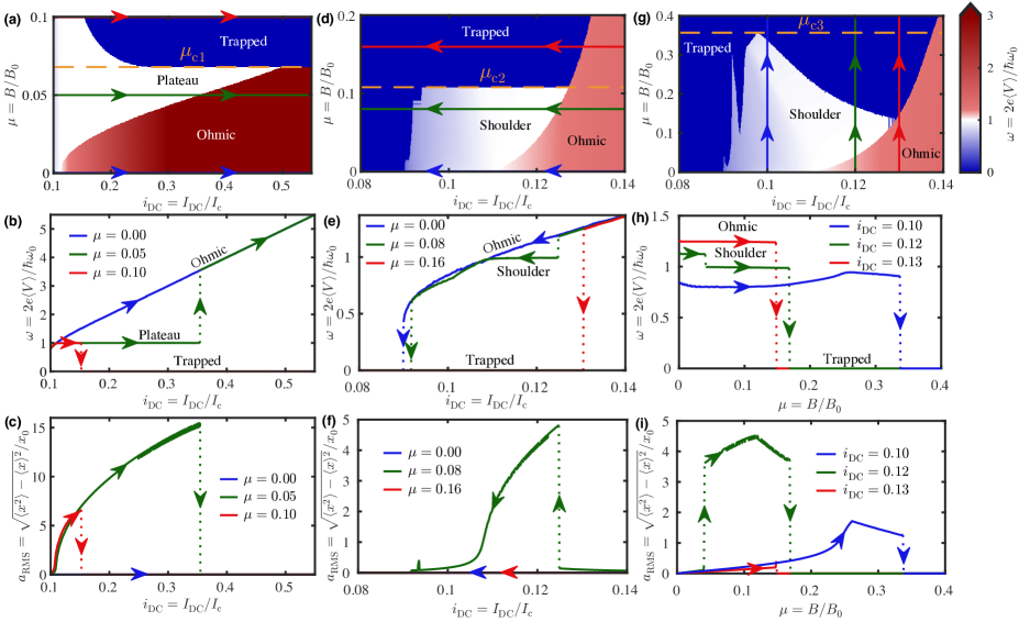
Fig. 3(a) shows the dimensionless DC voltage produced by increasing from the shoulder (keeping fixed) for a range of . For smaller than the first critical coupling ( for the parameters used in the figure) the width of the plateau increases quadratically with , as predicted by Eq. 7. Increasing beyond the plateau edge induces a transition to the Ohmic state, forming the hysteresis loop.
Our analysis shows that the picture above breaks down for . In stark contrast to the transition to the Ohmic state, here the system undergoes a sudden retrapping to the superconducting state from the voltage plateau due to large energy transfer from the electronic to the mechanical system. This has the effect of heavily reducing the plateau width and breaking the mechanical hysteresis loop (as shown in the cuts at fixed in Fig. 3(b)). Fig. 3(c) shows the amplitude of the mechanical oscillations corresponding to the cuts at constant in Fig. 3(b)). Oscillations are amplified while increasing on the voltage plateau until they are suddenly quenched at the plateau edge where retrapping occurs.
This is not the only example of a mechanically-induced retrapping in the DC IVC. Indeed, a similar scenario occurs even when reducing from the Ohmic state in an attempt to access the mechanical voltage shoulder, as shown in Fig. 3(d). For less than the second critical coupling ( for the chosen parameters) the voltage shoulder is accessible and mechanical oscillations are excited, whilst for premature retrapping occurs to the superconducting state mcdermott . The cuts at fixed of the dimensionless DC voltage in Fig. 3(e) and the corresponding mechanical amplitude in Fig. 3(f) show that the premature retrapping prevents the system from entering the shoulder state, resulting in the suppression of any mechanical oscillations and in the increase of the retrapping current.
It is important to point out that the IVC of the system changes if one instead performed the measurement by varying at a fixed current bias, as shown in Fig. 3(g). If (for the parameters in the figure) the system is in the superconducting state irrespective of the value of . If instead the system is prepared in the Ohmic state for and is increased from zero, a small voltage shoulder is accessible as shown in the cuts in Fig. 3(h). The resulting mechanical amplitude in Fig. 3(i) confirms the excitation of mechanical oscillations. The voltage shoulder generated by this procedure persists to values of larger than and . The maximum coupling at which shoulder states exist is labelled the third critical coupling . We point out that our numerical solution exhibits self-similar structures in the phase space, manifesting themselves as sharp tongues at and in Fig. 3(g). These correspond to micro-shoulders in the IVC at the fractional frequencies and respectively, due to the nonlinearity of the Josephson element. Accessing these micro-shoulders while decreasing (e.g. the green line in Fig. 3(d)) corresponds to the spike of mechanical amplitude observed at in Fig. 3(f).
To understand these retrappings analytically beyond the numerical approach above, we examine in detail the energy of the system. The dimensionless energy stored in the electronic system is equal to (expressed in units of the Josephson energy , see mcdermott ). While is oscillating in time, we find that a very effective condition for retrapping is obtained when its time average falls below the maximum of the Josephson potential i.e. . As the total energy is shared between the electronic and mechanical systems, the excitation of mechanical oscillations increases the mechanical energy at the expense of the electronic energy. Above a threshold coupling we may reach a point where the electronic system has too little energy to escape from a local minimum in the Josephson potential, causing a mechanically-induced retrapping to the superconducting state . As such, the activation of mechanical oscillations can be viewed as an additional damping mechanism for the electronic degrees of freedom.
In order to predict analytically when the retrapping occurs, the ansatzes (Eqs. 3 and 4) are substituted into the electronic energy to obtain an expression for (in-depth derivations of these results are available in the Supplementary Material). The retrapping region is plotted in red in Fig. 4.
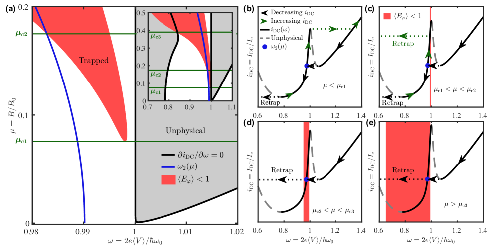
In Fig. 4(a) unphysical states () are indicated by grey shading in the phase space (), while the white regions indicate viable states. At this point, we just use the form of the current function to determine the frequency corresponding to a given DC bias and coupling . If this falls in the region , retrapping occurs, otherwise the system stays in the plateau or transitions back to the ohmic curve.
For no trapped states exist, and the IVC is determined by the weak coupling dynamics, summarised by the analytical IVC in Fig. 2(b), and corresponding to the qualitative sketch in Fig. 4(b). The shoulder is accessed by decreasing from the Ohmic branch until one reaches the local minimum with at in Fig. 4(b). By further reducing a sudden transition to the shoulder occurs, to the frequency (blue line in Fig. 4(a) and blue dot in Fig. 4(b)). Decreasing from here explores the shoulder of the voltage resonance, before the system retraps at the global minimum of the DC current () at . If instead is increased from the frequency , one explores the whole voltage plateau until the peak of the voltage resonance at , at which point the system transitions back to the Ohmic state (green dotted lines in Fig. 3(b) and Fig. 4(b)), forming the hysteresis loop.
For a trapped region appears in the phase space , for a window of frequencies less than . If the frequency of the system in the IVC enters this trapped region, the system will mechanically-retrap to the superconducting state. This is demonstrated in Fig. 4(c), where the system undergoes sudden mechanical retrapping whilst increasing along the voltage plateau. This mechanical retrapping (green dotted line in Fig. 4(c)) causes a truncation of the voltage plateau and the breaking of the hysteresis loop (corresponding to the red line in Fig. 3(b)). An analytical expression for can be derived by performing an expansion of in the small parameters and , yielding a minimum of the trapped contour at
| (8) |
Combining this critical value with the expression for in Eq. 7 we obtain the maximum size of the voltage plateau
| (9) |
that is independent of . For the parameters chosen here, this corresponds to a plateau width .
By progressively increasing above , one reaches a critical value of the coupling such that even the frequency is engulfed by the trapped region, as shown in Fig. 4(a). For the transition from the Ohmic branch to the voltage shoulder at is thus forbidden, and the system directly retraps to the superconducting state (as indicated in Fig. 4(d), corresponding to the red line in the numerical IVC in Fig. 3(e)). In order to calculate , we use an approximation of (see the Supplementary Material) and calculate its intersection with the contour , leading to
| (10) |
According to Eqs. (8) and (10) both and scale as , and they both diverge as , yielding a critical value above which the system can no longer retrap. Numerical investigation shows that such a critical value of does indeed exist, but is larger than predicted analytically, with a value . This quantitative disagreement arises due to the assumptions of and small oscillations being violated in this regime.
Even for , physically allowed states may exist between the global minimum of the curve (located at in Fig. 4(d)) and the retrapping region, but as is unstable these states cannot be accessed simply by reducing from the Ohmic branch. To access these states in the IVC, one may prepare the system at a frequency in this window at before increasing the coupling, corresponding to the numerical procedure in Fig. 3(g-i). As long as these states do not overlap with the red retrapping region, the system may access them even for . Indeed, the upper cutoff coupling is defined as the point where all physical states on the mechanical branch are engulfed by the retrapping region, as indicated in Fig. 4(e). In the zoomed out inset in Fig. 4(a), this corresponds to the intersection of the retrapping contour with the global minimum of the curve with . Since this minimum has a weak dependence on , we may approximate it by the uncoupled value i.e. . Substituting this into the retrapping contour and solving for yields
| (11) |
which predicts that is independent of . This is in excellent agreement with numerical simulations (see Supplementary Material).
V Discussion and Conclusions
In this paper we have shown how spontaneously-induced mechanical oscillations manifest themselves in the DC IVC of a suspended Josephson junction, under purely DC current bias. The coupling () between electronic and mechanical degrees of freedom can be controlled by means of an external in-plane magnetic field. We show that a mechanically induced hysteresis loop arises in the DC IVC, providing clear evidence of the activation and transduction of mechanical oscillations, even in the notoriously difficult GHz regime. We predict the appearance of a huge mechanically-induced voltage plateau in the IVC, of a width comparable to the junction critical current. The direct measurement of the plateau voltage directly relates to the mechanical resonance frequency
| (12) |
which is only marginally renormalised from the bare resonance frequency for typical suspended devices of large quality factor . The latter may be characterised by determining the critical coupling at which the large plateau is quenched. This results in a value
| (13) |
In the Supplementary Material we provide full details of the procedure to experimentally deduce all the parameters in our model. The large size of the voltage plateau combined with the independence of on the value of the electromechanical coupling may be exploited in metrology applications such as force and mass sensing. Despite the invariance of the DC voltage across the plateau, we show that the mechanical amplitude can be amplified continuously by increasing the DC bias current.
Our analytical investigation of the energy sharing between the electronic and the mechanical systems allows us to explain all the retrappings occurring in our system, and provides reliable estimates for the mechanical quality factor. Discrepancies between simulations and analytics can arise due to the breakdown of some of our approximations. In particular, the ratio becomes large at high current values on the plateau and near the upper critical coupling , and the single-frequency ansatz fails to capture the self-similar features in Figs. 3(d) and (g). These features occupy only a small region in the phase space, and we expect them to be challenging to detect experimentally.
One of the most important aspects of this work is the relative simplicity of the proposed experimental setup, that can be realised by both one and two-dimensional suspended weak links such as carbon nanotubes and graphene. The typical magnetic fields involved in the proposed experiments are of order (corresponding to ) for a very moderate . This is easily attainable for nano-scale devices, and can be further reduced using state of the art resonators with moser .
While the results discussed in the text are at zero temperature, the effect of finite temperature was studied via the addition of a Johnson-Nyquist noise current to Eq. 1 Lee . Performing stochastic simulations at finite , we find that the thermally increased retrapping current Kautz will cause the underdamped condition to break down at a critical value of , above which accessing the mechanical shoulder and plateau is not feasible. For example, a typical carbon nanotube resonator with permits plateau entry up to , a temperature attainable in a commercial dilution refrigerator. This may be further improved by using higher frequency mechanical resonators with resonant frequency of several hundred island . Once the underdamped condition is fulfilled, finite causes premature switching from the mechanically induced voltage plateau to the Ohmic state, resulting in a reduced plateau and hysteresis loop; this may be countered via the use of high resonators moser .
ACKNOWLEDGMENTS
This work was supported by the Engineering and Physical Sciences Research Council of the United Kingdom through the EPSRC Centre for Doctoral Training in Metamaterials (grant number EP/L015331/1), the EU H2020-MSCA-RISE project DiSeTCom (Project No. 823728) as well as by the Royal Society (Grant No. IEC/R2/192166).
References
- (1) B. Dong, H. Cai, G. I. Ng, P. Kropelnicki, J. M. Tsai, A. B. Randles, M. Tang, Y. D. Gu, Z. G. Suo and A. Q. Liu, Appl. Phys. Lett. 103, 181105 (2013).
- (2) K. Kim, X. Xu, J. Guo and D. L. Fan, Nat. Commun. 5, 3632 (2014).
- (3) J. E. Jang, S. N. Cha, Y. Choi, T. P. Butler, D. J. Kang, D. G. Hasko, J. E. Jung, Y. W. Jin, J. M. Kim and G. A. J. Amaratunga, Appl. Phys. Lett. 93, 113105 (2008).
- (4) A. Gaidarzhy, M. Imboden, P. Mohanty, J. Rankin and B. W. Sheldon, Appl. Phys. Lett. 91, 203503 (2007).
- (5) J. Moser, A. Eichler, J. Güttinger, M. I. Dykman and A. Bachtold, Nat. Nanotechnol. 9, 1007 (2014).
- (6) E. A. Laird, F. Pei, W. Tang, G. A. Steele and L. P. Kouwenhoven, Nano Letters 12, 193-197 (2012).
- (7) J. S. Bunch, A. M. van der Zande, S. S. Verbridge, I. W. Frank, D. M. Tanenbaum, J. M. Parpia, H. G. Craighead and P. L. McEuen, Science 315, 490-493 (2007).
- (8) C. Chen, S. Rosenblatt, K. I. Bolotin, W. Kalb, P. Kim, I. Kymissis, H. L. Stormer, T. F. Heinz and J. Hone, Nat. Nanotechnol. 4, 861–867 (2009).
- (9) B. Ilic, H. G. Craighead, S. Krylov, W. Senaratne, C. Ober and P. Neuzil, J. Appl. Phys 95, 3694 (2004).
- (10) M. Li, H. X. Tang and M. L. Roukes, Nat. Nanotechnol. 2, 114–120 (2007).
- (11) A. K. Naik, M. S. Hanay, W. K. Hiebert, X. L. Feng and M. L. Roukes, Nat. Nanotechnol. 4, 445–450 (2009).
- (12) M. Despont, J. Brugger, U. Drechsler, U. Dürig, W. Häberle, M. Lutwyche, H. Rothuizen, R. Stutz, R. Widmer, G. Binnig, H. Rohrer and P. Vettiger, Sensors and Actuators A: Physical 80, 100-107, (2000).
- (13) A. Bachtold, J. Moser and M. I. Dykman, Rev. Mod. Phys. 94, 045005, (2022).
- (14) K. Schwab, E. A. Henriksen, J. M. Worlock and M. L. Roukes, Nature 404, 974–977 (2000).
- (15) G. Sonne, R. I. Shekhter, L. Y. Gorelik, S. I. Kulinich, and M. Jonson, Phys. Rev. B 78, 144501 (2008).
- (16) G. Sonne and L. Y. Gorelik, Phys. Rev. Lett. 106, 167205 (2011).
- (17) M. T. Haque, M. Will, A. Zyuzin, D. Golubev and P. Hakonen, New J. Phys. 24, 103008 (2022).
- (18) A. Kretinin, A. Das and H. Shtrikman, arXiv:1303.1410v2.
- (19) A. Marchenkov, Z. Dai, B. Donehoo, R. N. Barnett and U. Landman, Nat. Nanotechnol. 2, 481 (2007).
- (20) B. H. Schneider, S. Etaki, H. S. J. van der Zant and G. A. Steele, Sci. Rep. 2, 599 (2012).
- (21) S. Etaki, F. Konschelle, Y. M. Blanter, H. Yamaguchi, and H. S. J. van der Zant, Nat. Commun. 4, 1803 (2013).
- (22) K. E. Khosla, M. R. Vanner, N. Ares, and E. A. Laird, Phys. Rev. X 8, 021052 (2018).
- (23) T. McDermott, H.-Y. Deng, A. Isaccson, E. Mariani, Phys. Rev. B 97, 014526 (2018).
- (24) B. D. Josephson, Phys. Lett. 1, 251 (1962).
- (25) K. K. Likharev, Rev. Mod. Phys. 51, 101 (1979).
- (26) S. Shapiro, Phys. Rev. Lett. 11, 80 (1963).
- (27) W. C. Stewart, Appl. Phys. Lett. 12, 277 (1968).
- (28) P. Jarillo-Herrero, J. A. van Dam and L. P. Kouwenhoven, Nature 439, 953–956 (2006).
- (29) H. B. Peng, C. W. Chang, S. Aloni, T. D. Yuzvinsky and A. Zettl, Phys. Rev. Lett. 97, 087203 (2006).
- (30) D. Garcia-Sanchez, A. San Paulo, M. J. Esplandiu, F. Perez-Murano, L. Forró, A. Aguasca and A. Bachtold, Phys. Rev. Lett. 99, 085501 (2007).
- (31) A. K. Hüttel, G. A. Steele, B. Witkamp, M. Poot, L. P. Kouwenhoven and H. S. J. van der Zant, Nano Lett. 9, 2547 (2009).
- (32) J.P. Cleuziou, W. Wernsdorfer, V. Bouchiat, T. Ondarçuhu and M. Monthioux, Nat. Nanotechnol. 1, 53 (2006).
- (33) M. Mergenthaler, A. Nersisyan, A. Patterson, M. Esposito, A. Baumgartner, C. Schönenberger, G. A. D. Briggs, E. A. Laird, and P. J. Leek, Phys. Rev. Appl. 15, 064050 (2021).
- (34) P. A. Lee, J. Appl. Phys. 42, 325-334 (1971).
- (35) R. L. Kautz and J. M. Martinis, Phys. Rev. B 42, 9903–9937 (1990).
- (36) J. O. Island, V. Tayari, A. C. McRae and A. R. Champagne, Nano Lett. 12, 4564–4569 (2012).