Emergent room-temperature ferroelectricity in spark-plasma sintered DyCrO3 and LaCrO3
Abstract
Identification of novel multiferroic materials with high-ordering temperatures remains at the forefront of condensed matter physics research. In this regard, the antiferromagnetic CrO3 compounds (like GdCrO3) constitute a promising class of multiferroic compounds, which, however, mostly become ferroelectric concomitant with the antiferromagnetic ordering much below room-temperature, arising from a subtle competition between the ferroelectric off-centering mode and a non-polar antiferrodistortive rotation mode that inhibits ferroelectricity. Recently, room-temperature ferroelectricity of structural origin, arising from off-centering displacements of R and Cr ions, has been identified in spark-plasma sintered GdCrO3 [Suryakanta Mishra et al., Phys. Rev. B 104, L180101 (2021)]. Interestingly, some of the experimentally observed non-ferroelectric RCrO3 compounds have been theoretically predicted to host similar ferroelectric instabilities. Here, we have identified two such non-ferroelectric RCrO3 compounds, one DyCrO3 (which is reported as a quantum paraelectric) and another LaCrO3 (which is paraelectric), and using a modified synthesis protocol involving spark-plasma-sintering (SPS), we have been successful in engineering an intrinsic room-temperature ferroelectricity in the paramagnetic state, driven by non-centrosymmetric structural phase in both SPS-sintered DyCrO3 and LaCrO3, in contrast to room-temperature paraelectricity in solid-state synthesized DyCrO3 and LaCrO3. While the ferroelectricity in SPS-prepared DyCrO3 and LaCrO3 is stable at room-temperature, it undergoes an irreversible transition from a ferroelectric (Pna21) phase to a paraelectric (Pbnm) phase at 440 K. Significantly, SPS-sintered LaCrO3, which undergoes antiferromagnetic ordering at 290 K, emerges as a promising near room-temperature multiferroic material.
I I. Introduction
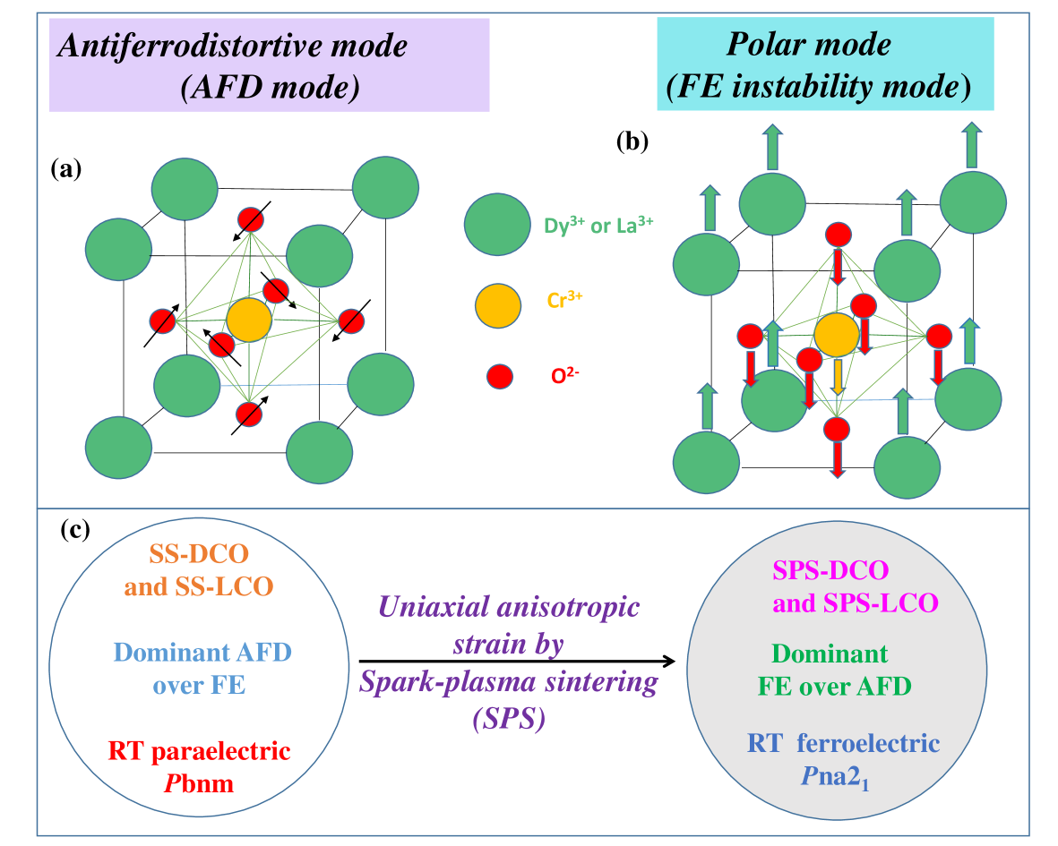
Multiferroic materials, which are ferroelectric (FE) and spontaneously magnetic (ferromagnetism or antiferromagnetism), are promising for fundamental and applied condensed matter physics research HSchmid (1994); DKhomskii (2009); YTokura (2003); JFScott (2006, 2007); RRamesh (2010); MMVopson (2015). Large magnetoelectric coupling in multiferroic materials necessitates the simultaneous emergence of FE and spontaneous magnetic ordering from the same structural unit, which, however, are usually contraindicated in most materials. For example, the ”-ness”, i.e. 3 (and hence diamagnetic) character of the transition metal cation in O3 perovskite-related compounds has often been stressed to be necessary to give rise to FE arising from co-operative off-center displacement of the -cations away from the negative charge center within the corresponding O6 octahedral cages. FE occurs, for instance, in BaTiO3 because the Ti4+(3) ions in the corresponding TiO6 octahedra are cooperatively off-centered HKrakauer (1990); RECohen (1992); KMRabe (1999). In case of O3 compounds containing non- cation, competing non-polar lattice instabilities related to antiferrodistortive (AFD) rotation modes of the O6 octahedra become energetically more favourable and thus compete with the polar off-centering mode (schematic visualizations of the AFD and FE instability modes are shown in Figs.1 (a) and (b)) PGhosez (2009, 1995); KMRabe (2009); HYHwang (2020); LQChen (2015); SMSelbach (2016); DVanderbilt (2013); RKovacik (2011). Following theoretical predictions PGhosez (2009); NASpaldin (2009); KMRabe (2010), it has now been verified experimentally that through appropriate lattice strain it becomes possible to tilt the energy balance away from the non-polar AFD modes and favour the polar off-centering mode in some ferroelectric MnO3 (=Sr, Ba, Ca) compounds containing non- Mn3) ion YTokura (2011); SLee (2021); MFiebig (2012). Large Born-effective charges and off-centering were detected for the Mn4+ ion in these MnO3 compounds, suggesting their dominant contribution to the observed novel FE PGhosez (2009); NASpaldin (2009).
The competition between AFD and FE instability modes is also very common in orthorhombic CrO3 CNRRao (2005); DTopwal (2017), which constitute an emerging class of multiferroic compounds. For example, FE is observed to arise concomitant with the antiferromagnetic (AFM) ordering at 170 K in standard solid-state sintered (SS) GdCrO3 BRajeswaran (2012). Similar ordering temperature for FE and AFM in most CrO3 (although much below room temperature) has led to contrasting reports in regards to the origin of FE, i.e. whether of structural or magnetic origin BRajeswaran (2012). Recently, by applying uniaxial pressure at high-temperatures through spark plasma sintering (SPS), we have stabilized FE at room-temperature in SPS GdCrO3, which still undergoes AFM ordering below 170 K DChoudhury (2021). FE in SPS GdCrO3, thus, clearly has a structural origin in the non-centrosymmetric Pna21 space group (also responsible for FE in SS GdCrO3 below 170 K) that involves polar, though opposite, off-center displacements for Cr and Gd ions DTopwal (2017); DChoudhury (2021). Some members of CrO3 family are, however, non ferroelectrics experimentally, such as DyCrO3, which is a quantum-paraelectric YPSun (2018) (quantum fluctuations and AFD instabilities suppress FE order at low temperatures HBurkard (1979)), and LaCrO3, which is a paraelectric CNRRao (2007); YIshii (2017); ZGYe (2007). Interestingly, although first-principles calculations deduce large Born-effective charges for La and Cr ions in LaCrO3 (similar to GdCrO3 and some other RCrO3 compounds) that suggest an incipient FE instability DTopwal (2017); RKovacik (2011); UVWaghmare (2008); DVanderbilt (2012), experimentally FE state has never been realized in DyCrO3 or in LaCrO3 at any temperatures. Here, we show that by adopting a dual synthesis protocol involving SPS, room-temperature FE can be engineered in DyCrO3 (also in LaCrO3) much above the corresponding AFM ordering temperature. Room-temperature intrinsic FE is verified using PUND (positive up–negative down) and PFM (piezoresponse force microscopy) measurements. The net FE distortion at room temperature due to stabilization of the noncentrosymmetric Pna21 phase involves dominant off-center displacements of 3+ ions in opposite direction to the Cr3+ off-center displacements. The estimated ferroelectric polarization, obtained using the atomic positions deduced from Rietveld refinement of corresponding synchrotron x-ray diffraction (XRD) data, is found to be in excellent agreement with the FE polarization values obtained from PUND experiments. Once synthesized, the obtained room-temperature FE Pna21 structure is stable, except against further heating under ambient pressures beyond 450 K, where it converts irreversibly to the centrosymmetric bnm phase (verified using dielectric, calorimetric and synchrotron XRD investigations). Solid-state synthesized (SS) DyCrO3 and LaCrO3 are found to be paraelectrics at room-temperature, which is in line with the previous literature. SPS synthesized LaCrO3, which is FE at room-temperature, undergoes magnetic ordering at 290 K, thus, coming very close to becoming the first room-temperature multiferroic material in this promising class of CrO3 compounds.
II II. Experimental Methodology
Standard solid-state synthesis was used to prepare SS DyCrO3 (SS-DCO) and SS LaCrO3 (SS-LCO) DChoudhury (2021); DTopwal (2018). For this, stoichiometric mixtures of Dy2O3, La2O3 and Cr2O3 were well ground and then calcined in two steps in air, first at 1300∘C and then at 1400∘C for 24 hours. Some part of SS-DCO and SS-LCO, thus prepared, were subjected to spark-plasma sintering (SPS) at 1300∘C for 15 minutes under 60 MPa pressure to obtain SPS-DCO and SPS-LCO. Room-temperature synchrotron powder X-ray diffraction (XRD) using a monochromatic X-ray beam of = 0.723 Å for DCO (SS-DCO, SPS-DCO, and SPS-DCO-ANN) and 0.721 Å for LCO (SS-LCO, SPS-LCO, and SPS-LCO-ANN) were carried out for structural phase characterizations. Rietveld refinements of room-temperature synchrotron XRD powder diffraction data were performed using FullProf software. Micro Raman measurements were performed using a 514 nm laser at room-temperature. The ferroelectric P-E loop and PUND (positive up–negative down) measurements were conducted using a Radiant P-E loop tracer JTEvans (2011); DChoudhury (2020). Piezoresponce force microscopy (PFM) measurements were also performed with 10 V, 150 Hz ac bias in contact mode to visualize polar domains. The dc magnetic and dielectric permittivity measurements were carried out with the help of a superconducting quantum interference device(SQUID) magnetometer and a LCR meter, respectively. Differential Scanning Calorimetric (DSC) measurements were also performed both in heating and cooling cycles to investigate the phase transition temperature.
III III. Results and discussions
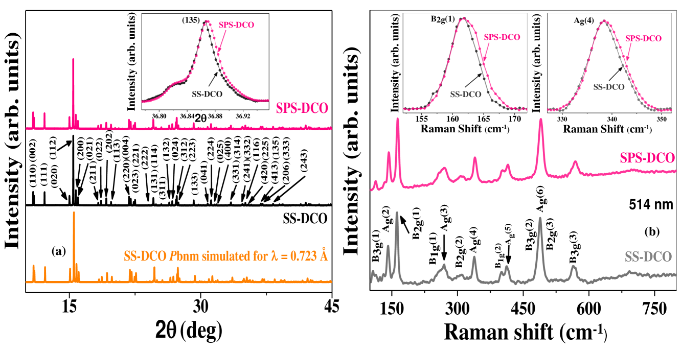
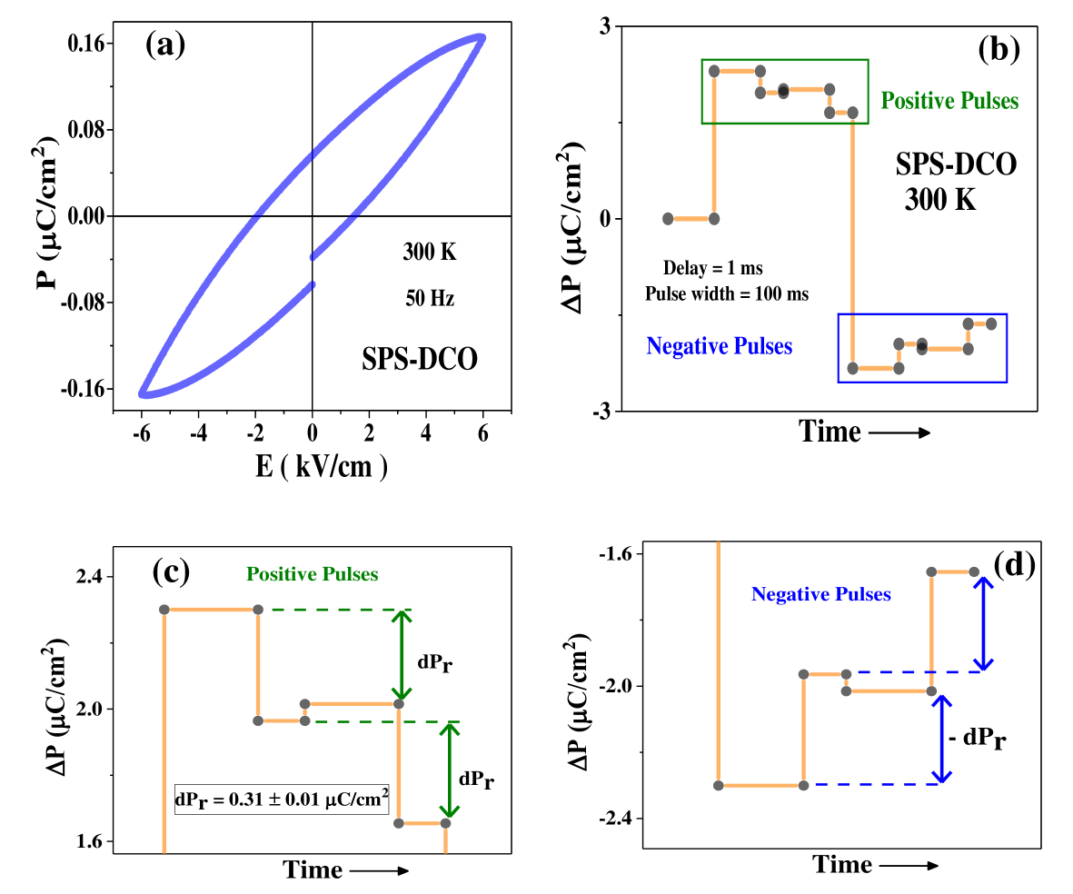
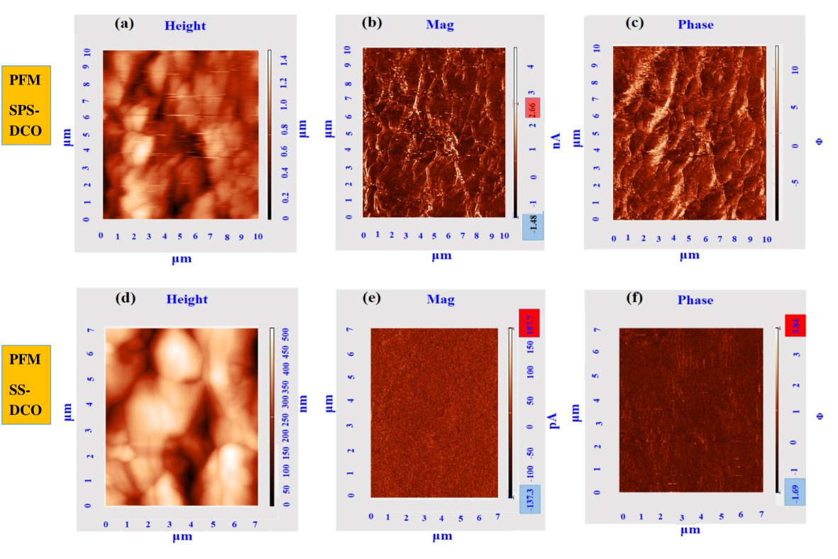
Due to similarities and for the sake of brevity and emphasis, we will largely address the methods and results involving DyCrO3 in this manuscript and will save the discussion of the significant results on LaCrO3 towards the later part of the manuscript. As seen through the synchrotron XRD data in Fig. 2(a) and room-temperature Raman data in Fig. 2(b), both SS-DCO and SPS-DCO are single-phase and appear to be structurally similar EMoran (2013); RIWalton (2012); MJain (2013). SPS-DCO, however, exhibits distinct peak-broadenings in comparison to SS-DCO both in the XRD and Raman data (mainly in modes related to Dy3+ ions and surrounding oxygen ions RIWalton (2012); MJain (2013)), origin of which will be discussed in further details later in the manuscript. Interestingly, we find a finite, though somewhat lossy, electric-polarization () vs. electric-field () loop at room-temperature in SPS-DCO (shown in Fig. 3(a)). In order to verify whether SPS-DCO is FE at room-temperature, we adopted the PUND FE characterization technique since it is a well-established and sensitive tool to extract out intrinsic FE from other extrinsic contributions BRajeswaran (2012); DChoudhury (2021); CNRRAO (2014); KHKim (2012, 2010); DChoudhury (2020). Remarkably, the room-temperature PUND results, as shown in Figs. 3(b)-(d), confirm the existence of finite, switchable intrinsic FE remanent polarization (dPr= 0.31 0.01 C/cm2) in SPS-DCO. Also, as seen in Figs. 4(a)-(c), different amplitude and phase contrast regions (corresponding to different ferroelectric domains) are identifiable in the piezoresponse-force microscopy (PFM) data on SPS-DCO at room temperature. While, due to the lossy nature of SS-DCO, reliable PUND measurements could not be carried out, PFM data on SS-DCO clearly show the absence of any piezoresponse, as seen in Figs. 4(d)-(f), elucidating the room-temperature paraelectric state in SS-DCO in contrast to the FE SPS-DCO.
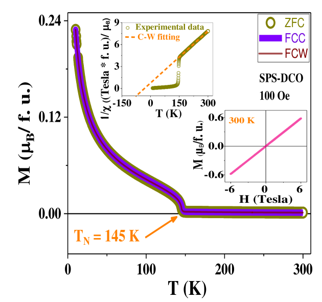
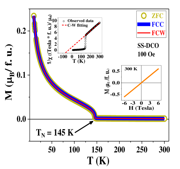
In order to investigate any role of magnetism to the observed room-temperature FE in SPS-DCO, temperature () and magnetic-field () dependent magnetization () measurements were carried out. As seen through the corresponding - and inverse magnetic-susceptibility - data of SPS-DCO in Fig. 5 and its upper inset, SPS-DCO undergoes a paramagnetic (PM) to antiferromagnetic (AFM) transition at 145 K. This is also consistent with a linear room-temperature - loop (without trace of any hysteresis) of SPS-DCO, as seen in the lower inset of Fig. 5. Importantly, all the above magnetic properties of SPS-DCO, including the PM to AFM transition temperature, are near-identical to that of SS-DCO (as seen in Fig. S3 and its insets SI (2022)) MJain (2013); PMohanty (2021); MJain (2021). Thus, any role of magnetism to the observed room-temperature FE in SPS-DCO can be clearly ruled out.
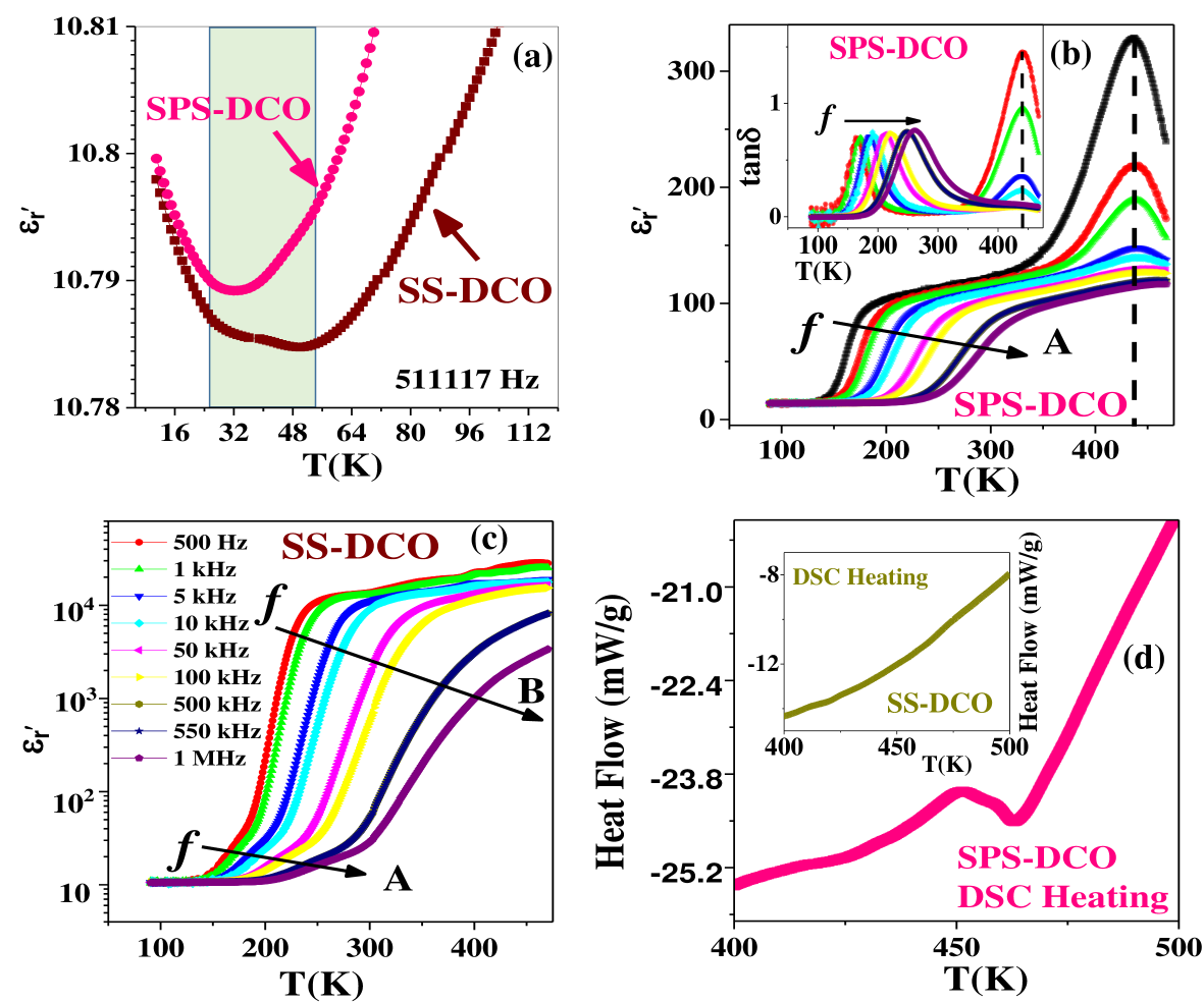
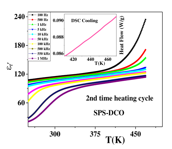
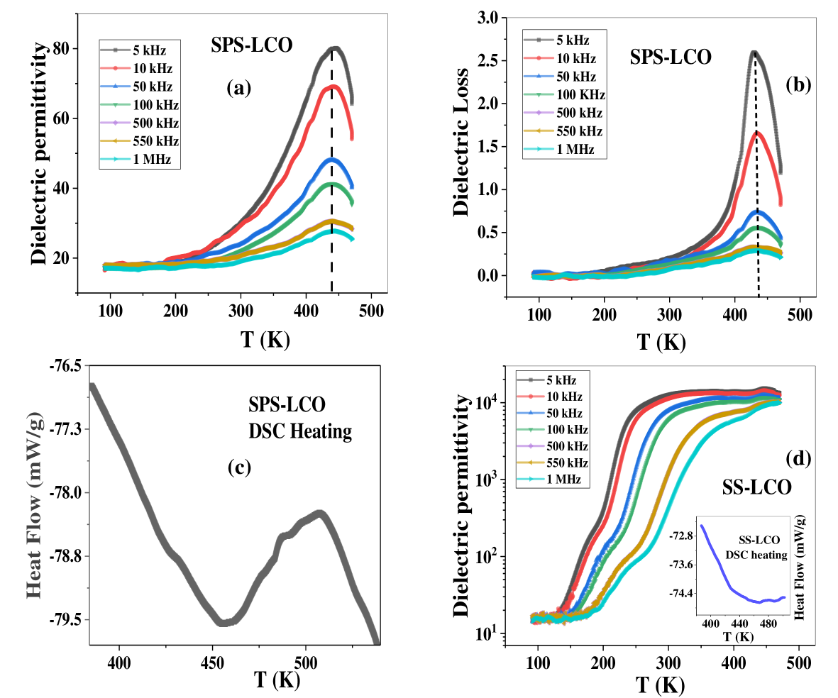
Small increment in the relative dielectric permittivity () values of polycrystalline SS-DCO below 50 K (illustrated by the shaded region in Fig. 6(a)) seems consistent with a low-temperature increase in seen in single-crystalline DyCrO3 (albeit at slightly higher temperatures) and that is reported to arise as a consequence of the quantum paraelectric nature of DyCrO3 YPSun (2018). For single-crystalline DyCrO3, a small increase (0.13) in is found to arise only along c-axis below 150 K (along other perpendicular two-axes, decreases with lowering of temperature). Understandably, due to averaging effect in polycrystalline samples, the corresponding rise in will become weaker and observable only at further lower temperature. Since SS-DCO do not exhibit any other transition around 50 K, the weak rise in below 50 K is understood to arise due to its reported quantum paraelectric state. At further lower temperatures of 20 K, spin-reorientation transition of Dy3+ spins in DyCrO3 leads to a further increase (seen in Fig. 6(a)) in values of DyCrO3 YPSun (2016). Interestingly, while the rise in values is clearly observable below the spin-reorientation transition in case of both SPS-DCO and SS-DCO, any rise in values is not observed for SPS-DCO below 50 K, likely suggesting the melting of the corresponding quantum paraelectric state in SPS-DCO. Further, a clear peak in -dependent and dielectric loss data (collected during heating run under ambient pressure), which does not disperse with varying electric-field frequencies, as seen in Figs. 6(b), clearly suggests that SPS-DCO undergoes a FE to paraelectric (presumably) phase transition at 440 K. The transition at 440 K in SPS-DCO also becomes clearly evident in the corresponding DSC data collected on SPS-DCO during the heating run, as seen in Fig. 6(d). Consistent with the room-temperature paraelectric state of SS-DCO, such a high-temperature dispersionless phase transition is not observable in the corresponding - data (which instead exhibits strong Maxwell-Wagner dielectric relaxation, marked as B in Fig. 6(c) ARvonHippel (1996); DChoudhury (2012); PNSanthosh (2020); the dielectric relaxation A at lower temperatures, which is similarly found in the case of SPS-DCO is currently being investigated in further details). Similarly, the DSC data of SS-DCO, collected in the heating run, do not exhibit signature of any high-temperature phase transition, as seen in the inset to Fig. 6(d). Importantly, the observed FE in SPS-DCO is found to be reproducible and stable at room-temperature over a gap of many months (the maximum that we have checked for is after a gap of 12 months), as shown in Fig. S4 of SI (2022).
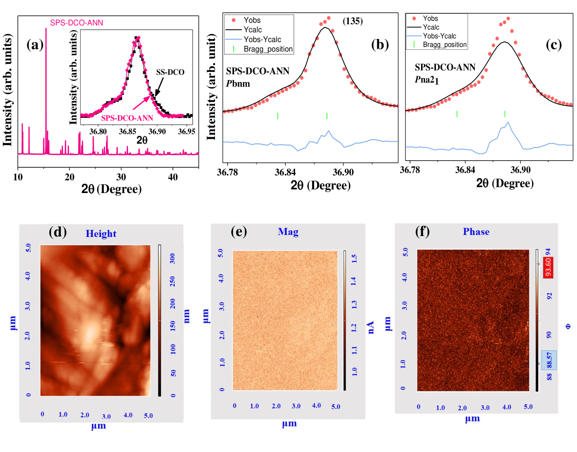
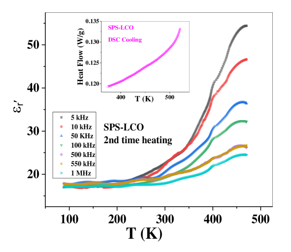
To investigate whether the obtained room-temperature FE in SPS-DCO is a thermodynamically-stabilized or kinetically-stabilized phase, -dependent in subsequent heating cycles and DSC measurements in subsequent cooling and heating cycles were performed under ambient-pressure condition. Interestingly, the peak in in subsequent heating and the corresponding peak in the DSC cooling at 440 K is absent, as seen in Fig. S1 of SI (2022). To further verify, SPS-DCO had been further annealed at 1300∘ C in air under ambient pressure condition and slowly cooled to room temperature to form SPS-DCO-ANN. Consistent with the paraelectric state of SPS-DCO-ANN at room temperature, corresponding PFM data (shown in Figs. S2(d)-(f)) do not show any phase and amplitude contrast. These measurements, thus, clearly elucidate that room-temperature FE in SPS-DCO is a kinetically arrested phase, that is unstable against heating of the sample beyond 440 K.
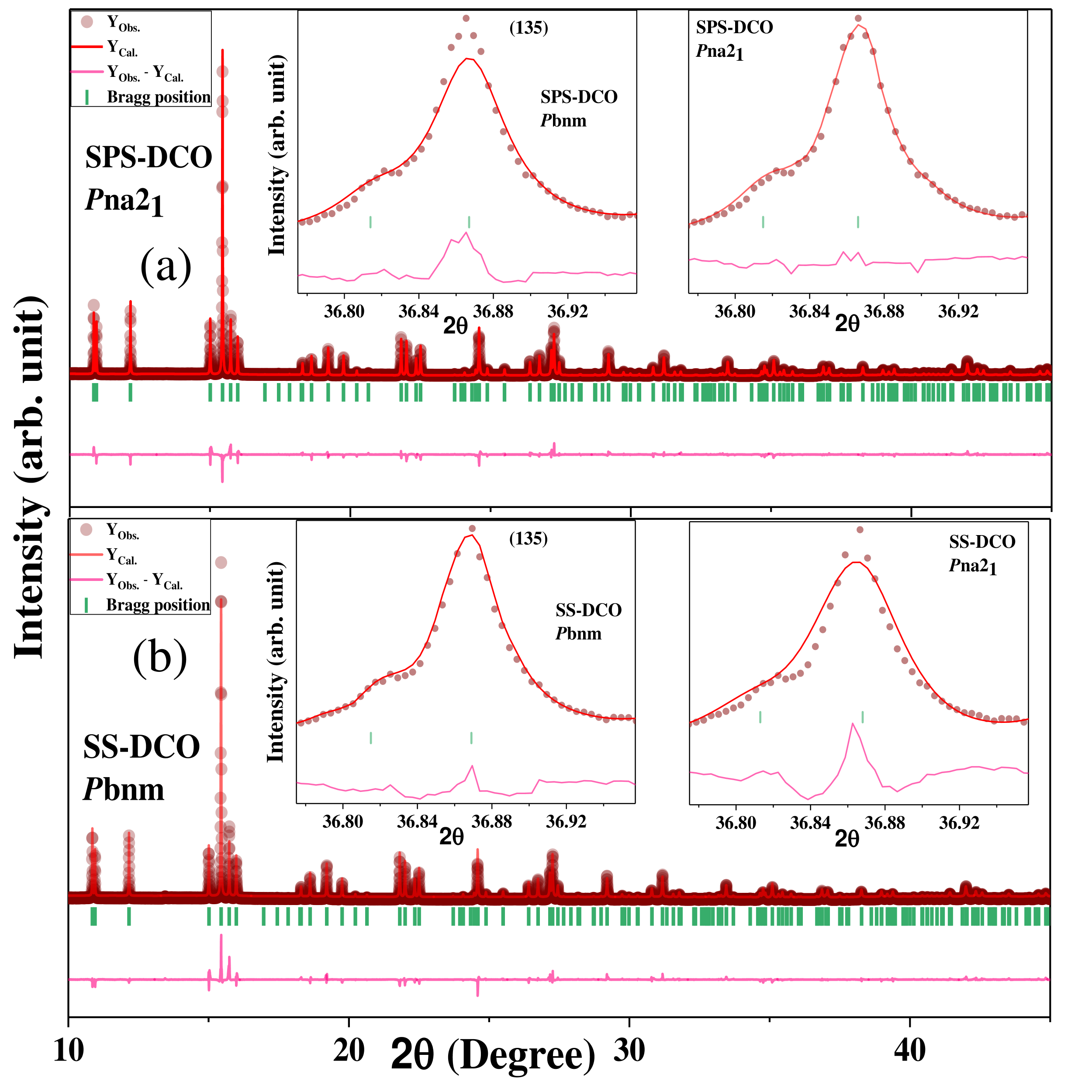
In order to understand the structural phase responsible for room-temperature FE in SPS-DCO, we refer to our earlier first-principles calculations on the relative energy stability among the various possible structural space groups in the CrO3 compounds DChoudhury (2021). Results from our first-principles calculation, which is also in consistence with other similar investigations DTopwal (2017), suggest that two structural space groups, centrosymmetric Pbnm and non-centrosymmetric Pna21 are energetically more favourable (the energy difference between these two structures is within our calculation error limit) in case of many of the CrO3 compounds. Consistent with the above, the paraelectric to ferroelectric phase transition in CrO3 materials have also been ascribed to a phase transition between the bnm to the na21 structures, respectively SGiri, (2014); DTopwal (2017); SGiri (2015). Accordingly, we have refined the room-temperature synchrotron XRD spectra of SS-DCO and SPS-DCO by adapting both the Pbnm and the Pna21 space groups (refined lattice parameters are shown in Table-I SI (2022)). Interestingly, while the room-temperature XRD spectrum of SPS-DCO can be better fitted using the non-centrosymmetric na21 space group, the same for SS-DCO can be better accounted for by adapting the centrosymmetric bnm space group, as seen in Fig. 7. In addition, the structure of SPS-DCO-ANN, as determined from room-temperature synchrotron XRD data, is found to be better described with centrosymmetric Pbnm in consistence with its room-temperature paraelectric state (shown in Figs. S2(a)-(c) of SI (2022)). Using the refined structural parameters of the na21 space group for SPS-DCO, the ionic contribution to the ferroelectric polarization was calculated using the formula reported in Refs. SGiri, (2014); DChoudhury (2021). Significantly, the calculated ionic contribution to the FE polarization comes out to be 0.1117 0.0001 C/cm2, which agrees very well with the remanant FE polarization value (i.e. P= 0.155 0.01 C/cm2 where P= dPr) obtained in room-temperature PUND experiments on SPS-DCO.
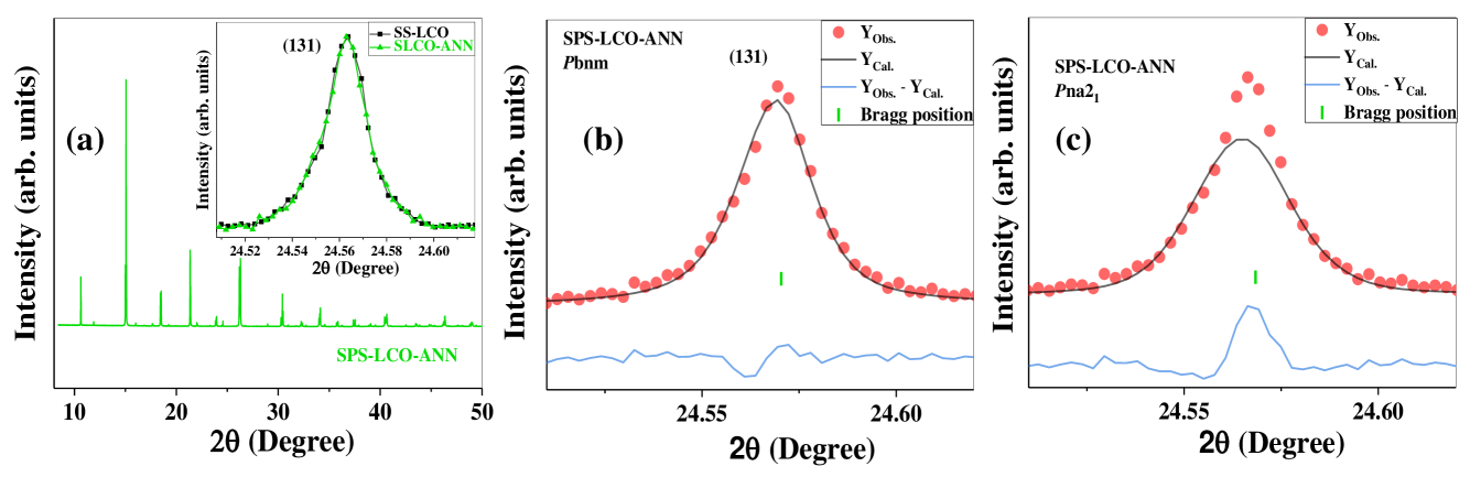
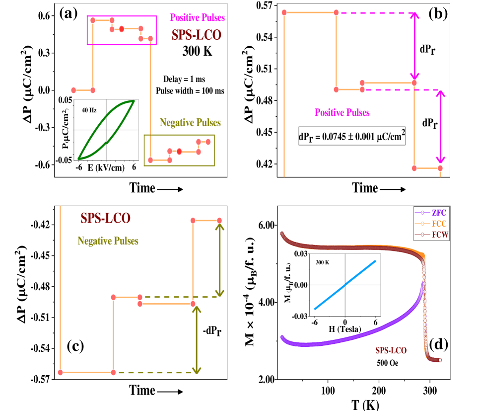
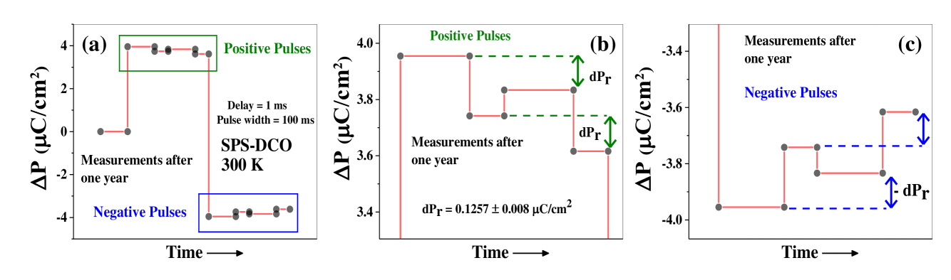
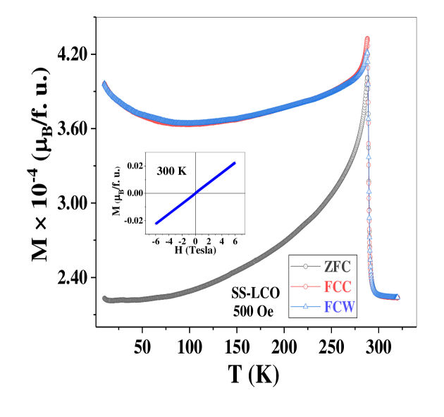
Further, we also report intrinsic room-temperature ferroelectricity in SPS-LCO (results of room-temperature - and PUND measurements are shown in Figs. 8(a)-(c)), whereas SS-LCO remains paraelectric (supported data are shown in Fig. S6(d) and Fig. S9(b) of SI (2022)), as reported earlier. In consistence with the above, SPS-LCO and SS-LCO are found to crystallize in the noncentrosymmetric Pna21 and centrosymmetric Pbnm phases at room temperature, respectively (corresponding synchrotron XRD and refinement results are shown in Fig. S8, Fig. S9 and Table-II of SI (2022)). Interestingly, both SPS-LCO and also SS-LCO undergo AFM ordering just below room-temperature, at 290 K (- data of SPS-LCO is shown in Fig. 8(d) and corresponding data of SS-LCO is shown in Fig. S5 of SI (2022)) CNRRao (2007); YIshii (2017); ZGYe (2007); JBGoodenough (2011). The room-temperature ferroelectricity in SPS-LCO, while reproducible and stable at room-temperature, undergo a similar irreversible FE to paraelectric phase transition (corresponding dispersionless transition in - and DSC data, collected during the heating runs, are included in Figs. S6(a)-(C) of SI (2022)) at high temperatures similar to SPS-DCO (Fig. S7 of SI (2022)). A similarly annealed SPS-LCO, SPS-LCO-ANN (annealed under similar conditions as SPS-DCO-ANN) is found to crystallize in the centrosymmetric Pbnm phase (corresponding synchrotron XRD data and refinement results are shown in Fig. S10 of SI (2022)) establishing the kinetic origin of ferroelectricity in SPS-LCO. SPS-LCO, however, exhibits a lower FE polarization as compared to SPS-DCO at room-temperature, likely because the ionic radius of La3+ ions is much larger than Dy3+, which causes a smaller magnitude of off-center displacement of La3+ ion in SPS-LCO as compared to Dy3+ ion in SPS-DCO. Also, the calculated ionic contribution to the ferroelectric polarization, using the refined atomic positions (from synchrotron XRD refinement results) of SPS-LCO come out to be 0.01908 0.0001 C/cm2, which is in good agreement with the experimentally determined remanent FE polarization value ( 0.0373 0.001 C/cm2) of SPS-LCO. Significantly, SPS-LCO becomes multiferroic below 290 K, which is the highest in this CrO3 family and is very close to becoming a room-temperature multiferroic material.
IV IV. Summary
In conclusion, we successfully engineer room-temperature ferroelectricity in both DyCrO3 and LaCrO3 when they are synthesized using a modified protocol that involves spark-plasma sintering (SPS) at high temperatures, despite being traditionally classified as quantum-paraelectric and paraelectric materials, respectively. This is the first experimental realization of ferroelectricity (FE) in either of these compounds, despite the theoretical prediction of a ferroelectric (FE) instability over antiferrodistortive (AFD) non-polar modes. In contrast, the solid-state synthesized (SS) DyCrO3 and LaCrO3 are found to remain paraelectrics, following earlier reports. Even though the magnetic properties of the SPS and SS synthesized compounds are the same and they both go through antiferromagnetic ordering at temperatures lower than room temperature, it is important to note that the room-temperature FE in both the SPS synthesized compounds is found to be of structural origin arising from off-centering displacements of rare-earth and Cr ions. The kinetically-arrest process during SPS that leads to the room-temperature FE phase likely prefers the FE instability modes over the AFD modes in this emerging class of RCrO3 multiferroic compounds.
V V. Acknowledgments
SM would like to acknowledge the financial support from MoE, India. DC acknowledges STARS, MoE, India (MoE-STARS/STARS-1/238) for financial support. SM and DC would like to acknowledge the use of the Raman spectroscopy and SPS central facilities at IIT Kharagpur. DC would like to acknowledge insightful discussions with Professor D. D. Sarma.
References
- HSchmid (1994) H. Schmid, Ferroelectrics 162, 317 (1994).
- DKhomskii (2009) D. Khomskii, Physics 2, 20 (2009).
- YTokura (2003) T. Kimura, T. Goto, H. Shintani, K. Ishizaka, and Y Tokura, Nature (London) 426, 55 (2003).
- JFScott (2006) W. Eerenstein, N. D. Mathur, and J. F. Scott, Nature (London) 442, 759 (2006).
- JFScott (2007) J. F. Scott, Nat. Mat. 6, 256 (2007).
- RRamesh (2010) N. A. Spaldin, S.-W. Cheong, and R Ramesh, Phys. Today 63, 38 (2010).
- MMVopson (2015) M. M. Vopson, Crit. Rev. Solid State Mater. Sci. 40, 223 (2015).
- HKrakauer (1990) R. E. Cohen, and H. Krakauer, Phys. Rev. B 42, 6416 (1990).
- RECohen (1992) R. E. Cohen, Nature 358, 136 (1992).
- KMRabe (1999) Ph. Ghosez, E. Cockayne, U. V. Waghmare, and K. M. Rabe, Phys. Rev. B 60, 836 (1999).
- PGhosez (2009) S. Bhattacharjee, E. Bousquet, and P Ghosez, Phys. Rev. Lett. 102, 117602 (2009).
- PGhosez (1995) W. Zhong, and D Vanderbilt, Phys. Rev. Lett. 74, 2587 (1995).
- KMRabe (2009) C. -J. Eklund, C. J. Fennie, and K. M. Rabe, Phys. Rev. B 79, 220101(R) (2009).
- HYHwang (2020) R. Xu, J. Huang, E. S. Barnard, S. S. Hong, P. Singh, E. K. Wong, T. Jansen, V Harbola, J. Xiao, B. Y. Wang, S. Crossley, D. Lu, S. Liu, and H. Y. Hwang, Nat. Commun. 11, 3141 (2020).
- LQChen (2015) M. D. Biegalski, L. Qiao, Y. Gu, A. Mehta, Q. He, Y. Takamura, A. Borisevich, and L. -Q. Chen, App. Phys. Lett. 106, 162904 (2015).
- SMSelbach (2016) A. Marthinsen, C. Faber, U. Aschauer, N. A. Spaldin, and S. M. Selbach, MRS commun. 6, 182 (2016).
- DVanderbilt (2013) J. Hong, and D. Vanderbilt, Phys. Rev. B 87, 064104 (2013).
- RKovacik (2011) C. Ederer, T. Harris, and R. Kovác̆ik, Phys. Rev. B 83, 054110 (2011).
- NASpaldin (2009) J. M. Rondinelli, A. S. Eidelson, and N. A. Spaldin, Phys. Rev. B 79, 205119 (2009).
- KMRabe (2010) J. H. Lee, and K. M. Rabe, Phys. Rev. Lett. 104, 207204 (2010).
- YTokura (2011) H. Sakai, J. Fujioka, T. Fukuda, D Okuyama, D. Hashizume, F. Kagawa, H Nakao, Y. Murakami, T. Arima, A. Q. R. Baron, Y. Taguchi, and Y. Tokura, Phys. Rev. Lett. 107, 137601 (2011).
- SLee (2021) H. An, Y. -G. Choi, Y. -R. Jo, H. J. Hong, J. -K Kim, O. Kwon, S. Kim, M. Son, J. Yang, J. -C. Park, H. Choi, J. Lee, J. Song, M. -H Ham, S. Ryu, Y. Kim, C. W. Bark, K. -T. Ko, B. -J. Kim, and S. Lee, NPG Asia Materials 13, 69 (2021).
- MFiebig (2012) T. Gnter, E. Bousquet, A. David, Ph. Boullay, Ph. Ghosez, W. Prellier, and M. Fiebig, Phys. Rev. B 85, 214120 (2012).
- CNRRao (2005) C. R. Serrao, A. K. Kundu, S. B. Krupanidhi, U. V. Waghmare, and C. N. R. Rao, Phys. Rev. B 72, 220101(R) (2005).
- DTopwal (2017) S. Mahana, B. Rakshit, R. Basu, S. Dhara, B. Joseph, U. Manju, S. D. Mahanti, and D. Topwal, Phys. Rev. B 96, 104106 (2017).
- BRajeswaran (2012) B. Rajeswaran, D. I. Khomskii, A. K. Zvezdin, C. N. R. Rao, and A. Sundaresan, Phys. Rev. B 86, 214409 (2012).
- DChoudhury (2021) S. Mishra, Keerthana, K Rudrapal, A. Rahaman, P. Pal, A. Sagdeo, R. Mishra, D. Topwal, A. R. Chaudhuri, V. Adyam, and D. Choudhury, Phys. Rev. B 104, L180101 (2021).
- YPSun (2018) L. H. Yin, T. F. Shi, R. R. Zhang, C. B. Park, K. H Kim, J. Yang, P. Tong, W. H. Song, J. M. Dai, X. B. Zhu, W. S. Yan, and Y. P. Sun, Phys. Rev. B 98, 054301 (2018).
- HBurkard (1979) K. A. Mller, and H. Burkard, Phys. Rev. B 19, 3593 (1979).
- CNRRao (2007) J. R. Sahu, C. R. Serrao, N. Ray, U. V. Waghmare, and C. N. R. Rao, J. Mater. Chem. 17, 42 (2007).
- YIshii (2017) K. Yoshii, N. Ikeda, Y. Shimojo, and Y. Ishii, Materials Chemistry and Physics 190, 96 (2017).
- ZGYe (2007) H-Y. Guo, J. I. L Chen, and Z-G Ye, J. Mater. Res. 22, 2081 (2007).
- UVWaghmare (2008) N. Ray, and U. V. Wagmare, Phys. Rev. B 77, 134112 (2008).
- DVanderbilt (2012) J. Hong, A. Stroppa, and J. iguez, S. Picozzi, and D. Vanderbilt, Phys. Rev. B 85, 054417 (2012).
- DTopwal (2018) S. Mahana, U. Manju, and D. Topwal, J. Phys. D: Appl. Phys. 51, 305002 (2018).
- JTEvans (2011) J. T. Evans, Proc. IEEE ISAF 1 (2011).
- DChoudhury (2020) P. Pal, K. Rudrapal, S. Mahana, S. Yadav, T. Paramanik, S. Mishra, K. Singh, G. Sheet, D. Topwal, A. R. Chaudhuri, and D. Choudhury, Phys. Rev. B 101, 064409 (2020).
- EMoran (2013) J. P. Gonjal, R. Schmidt, J. -J.Romero, D. Ávila, U. Amador, and E. Morán, Inorg. Chem 52, 313 (2013).
- RIWalton (2012) M. C. Weber, J. Kreisel, P. A. Thomas, M. Newton, K. Sardar, and R. I. Walton, Phys. Rev. B 85, 054303 (2012).
- MJain (2013) A. McDannald, L. Kuna, and M. Jain, J. Appl. Phys. 114, 113904 (2013).
- CNRRAO (2014) R. Saha, A. Sundaresan, and C. N. R Rao, Mater. Horiz 1, 20 (2014).
- KHKim (2012) Y. S. Chai, Y. S. Oh, L. J. Wang, N. Manivannan, S. M. Feng, Y. S. Yang, L. Q. Yan, C. Q. Jin, and K. H. Kim, Phys. Rev. B 85, 184406 (2012).
- KHKim (2010) S. M. Feng, Y. S. Chai, J. L. Zhu, N. Manivannan, Y. S. Oh, L. J. Wang, Y. S. Yang, C. Q. Jin, and K. H. Kim, New J. Phys. 12, 073006 (2010).
- SI (2022) See Supplementary material at [URL will be provided by publisher].
- PMohanty (2021) E. T. Sibanda, A. R. E. Prinsloo, C. J. Sheppard, and P. Mohanty, AIP Advances 12, 035342 (2022).
- MJain (2021) A. McDannald, L. Kuna, M. S. Seehra, and M. Jain, Phys. Rev. B 91, 224415 (2015).
- YPSun (2016) L. H. Yin, J. Yang, P. Tong, X. Luo, C. B. Park, K. W. Shin, W. H. Song, J. M. Dai, K. H. Kim, X. B. Zhua, and Y. P. Sun, J. Mater. Chem. C 4, 11198 (2016).
- ARvonHippel (1996) A. R. von Hippel, Dielectrics and Waves (MIT Press, Cambridge, MA, 1966).
- DChoudhury (2012) D. Choudhury, P. Mandal, R. Mathieu, A. Hazarika, S. Rajan, A. Sundaresan, U. V. Waghmare, R. Knut, O. Karis, P. Nordblad, and D. D. Sarma, Phys. Rev. Lett. 108, 127201 (2012).
- PNSanthosh (2020) V. K. Anusree, P. N. Lekshmi, S. G. Bhat, A. A. Wagh, G. Das, and P. N Santhosh, J. Appl. Phys. 127, 194105 (2020).
- SGiri (2015) A. Ghosh, A. Pal, K. Dey, S. Majumdar, and S. Giri, J. Mater. Chem. C 3, 4162 (2015).
- SGiri, (2014) A. Ghosh, K. Dey, M. Chakraborty, S. Majumdar, and S. Giri, Europhys. Lett. 107, 47012 (2014).
- JBGoodenough (2011) J. -S. Zhou, J. A. Alonso, A.Muoz M. T. Fernández-Díaz, and J. B. Goodenough, Phys. Rev. Lett. 106, 057201 (2011).
VI SUPPLEMENTARY MATERIAL
VII VI. Temperature dependencies of relative dielectric permittivity collected in 2nd heating cycle, and DSC data of SPS-DCO in cooling cycle
VIII VII. Lattice parameters obtained from Rietveld refinement of room temperature synchrotron XRD of SPS- DCO and SS-DCO
. SPS-DCO-Pna21 SS-DCO-Pbnm a = 5.53309(3) Å a = 5.27954(2) Å b = 5.27900(2) Å b = 5.53203(3) Å c= 7.57270(3) Å c= 7.57316(3) Å
IX VIII. Room-temperature synchrotron XRD, Rietveld refinement, and room-temperature PFM images of SPS-DCO-ANN sample
X IX. Magnetization (M) vs. temperature (T) data of SS-DCO
XI X. The room temperature PUND measurements on a separate piece of SPS-DCO after one year
XII XI. Magnetization (M) vs. temperature (T) data of SS-LCO
XIII XII. Temperature dependencies of relative dielectric permittivity, dielectric loss, and DSC heating data of SPS-LCO and SS-LCO
XIV XIII. Temperature dependencies of relative dielectric permittivity data collected in 2nd heating cycle, and DSC cooling data of SPS-LCO
XV XIV. Room temperature synchrotron XRD spectra of SPS-LCO and SS-LCO

XVI XV. Rietveld refinement of room temperature synchrotron XRD spectra of SPS-LCO and SS-LCO

XVII XVI. Lattice parameters obtained from Rietveld refinement of room temperature synchrotron XRD of SPS- LCO and SS-LCO
. SPS-LCO-Pna21 SS-LCO-Pbnm a = 5.476329(20) Å a = 5.508203(11) Å b = 5.511812(18) Å b = 5.472083(12) Å c= 7.75341(3) Å c= 7.748075(17) Å
XVIII XVII. Room temperature synchrotron XRD spectra and Rietveld refinement of SPS-LCO-ANN