Harnessing asymmetry to reprogram nonlinear metamaterials on-the-fly with no moving parts
Abstract
Various two-dimensional fabrication methods, such as deposition, etching, milling, laser cutting, and water jetting, suffer from asymmetry between the top and the bottom surface of fabricated parts. Such asymmetry is usually undesirable and can compromise functionality, or at least add uncertainty to fabricated components. The common practice is to assume symmetry between the top and the bottom surfaces by using average dimensions. In this study, we harness such asymmetry to realize metamaterials with dynamically tunable (i. e., re-programmable) properties. Our metamaterial is composed of identical unit cells with two concentric Archimedean spiral cuts and a permanent magnet embedded in the unit cell’s center. By utilizing external electromagnets, we further amplify the fabrication asymmetry, through the inherent asymmetry between a repulsive vs attractive state between the permanent magnets and the electromagnets. We demonstrate the utility of our metamaterials by programming its spatiotemporal response in both time and frequency even in the presence of high amplitude harmonic excitation. Our findings can be utilized for broad range of applications, from seismic sensing at low frequency to ultrasonic imaging at higher frequencies.
Metamaterials are arrangements of basic building blocks, or unit cells, that repeat in space giving rise to unconventional negative effective properties Lu et al. (2009); Maldovan (2013); Hussein et al. (2014); Cummer et al. (2016). For example, metamaterials can support the formation of frequency band gaps where elastic/acoustic waves are forbidden from propagation Bilal and Hussein (2013); Deymier (2013). Potential applications of such metamaterials are sound insulation/attenuation Yang et al. (2010); Mei et al. (2012), wave-guidingDing et al. (2010); Li et al. (2019); Wang et al. (2023), focusing Torrent and Sánchez-Dehesa (2007); Yang et al. (2004); Li et al. (2012), cloaking Cummer and Schurig (2007); Torrent and Sánchez-Dehesa (2008); Cummer et al. (2008), filtering Pennec et al. (2004); Zhu and Semperlotti (2013); Liao et al. (2021) or localizationBoechler et al. (2010). Despite their great potential in manipulating waves, metamaterials with fixed properties could be less desirable in practical applications. Therefore, a great deal of research is dedicated to realizing metamaterials with tunable properties. Examples of tunable acoustic/elastic metamaterials include utilizing varying air pressure Lee et al. (2012); Langfeldt et al. (2016), external load Wang et al. (2014); Kheybari et al. (2022a); Roshdy et al. (2023), buckling Zhang et al. (2022); Kheybari et al. (2022b), piezoelectric patches Airoldi and Ruzzene (2011); Sugino et al. (2017); Chen et al. (2013); Casadei et al. (2012); Hou and Assouar (2015); Sugino et al. (2020); Yi et al. (2020); Celli et al. (2018); Alshaqaq et al. (2022); Degraeve et al. (2014); Li et al. (2022), electric fields Xiao et al. (2015), electromagnetsMa et al. (2018); Wang et al. (2016); Chen et al. (2016); Yang et al. (2017); Haghpanah et al. (2016); Salari-Sharif et al. (2019); Liu et al. (2019); Gao et al. (2023), magnetic fields Bilal et al. (2017a, b); Robillard et al. (2009); Vasseur et al. (2011); Allein et al. (2016); Chen et al. (2014); Zhao et al. (2017); Guell Izard and Valdevit (2020); Zhang et al. (2021), acoustic trapping Caleap and Drinkwater (2014), granular contacts Li et al. (2014); Boechler et al. (2011), and shape memory effects Chuang et al. (2019); Hu et al. (2018); Candido de Sousa et al. (2018); Lv et al. (2020); Gliozzi et al. (2020); Li et al. (2021); Sepehri et al. (2021); Song and Shen (2022). Some of these tuning methods are irreversible, relatively slow, require manual intervention, moving parts, direct contact with the metamaterials or limited to low amplitude waves Cummer et al. (2016); Chen et al. (2018); Zangeneh-Nejad and Fleury (2019); Kumar and Pueh Lee (2019); Ji and Huber (2021); Xia et al. (2022).
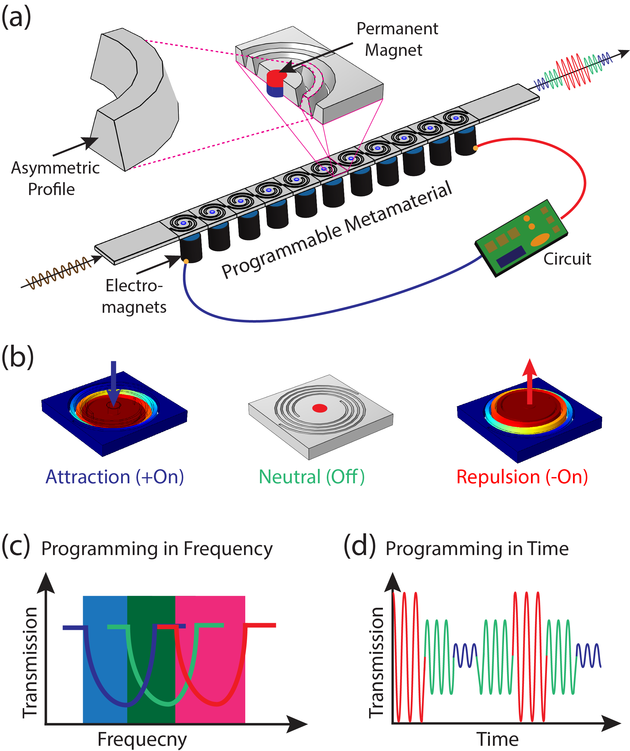
In this study, we design, analyze and experimentally realize a class of re-programmable metamaterial that can be actively tuned to manipulate elastic waves on-the-fly with no contact, no moving parts, continuous tunability, while being able to filter targeted fundamental or higher harmonics, by design. We refer to our metamaterial as re-programmable, because the tuning of the material’s spatiotemporal properties is reversible. Our metamaterial is composed of a basic building block that repeats periodically in space (i.e., unit cell). Each unit cell features two concentric Archimedean spiral cuts with a permanent magnet embedded at its center. All the permanent magnets are oriented in the same direction (i.e., north facing up). The spiraling cuts within the unit cell have asymmetric profiles across the thickness (Fig.1 (a)). To affect a dynamical change in our material’s properties, we place an array of electromagnets underneath the metamaterial sample. The electromagnets are connected in parallel to a DC power supply and are controlled by a pre-programmed electric circuit. The metamaterial can have one of three states depending on the programmed polarity (positive, off, or negative) of the electromagnets: (i) attraction between the permanent magnets and the electromagnets, (ii) neutral when the electromagnets are off, or (iii) repulsion between the permanent magnets and the electromagnets (Fig.1 (b)). The spatiotemporal characteristics of the metamaterial are dynamically tuned by programming the state of the metamaterial’s surrounding magnetic field over time. The tunability of our metamaterial can be achieved for a band of frequencies by shifting the band gap region within the frequency spectrum (Fig.1 (c)). The tunability can also be achieved for the frequency contents of a single harmonic excitation over specific time intervals by selectively attenuating particular harmonics within the transmitted signal (Fig.1 (d)).
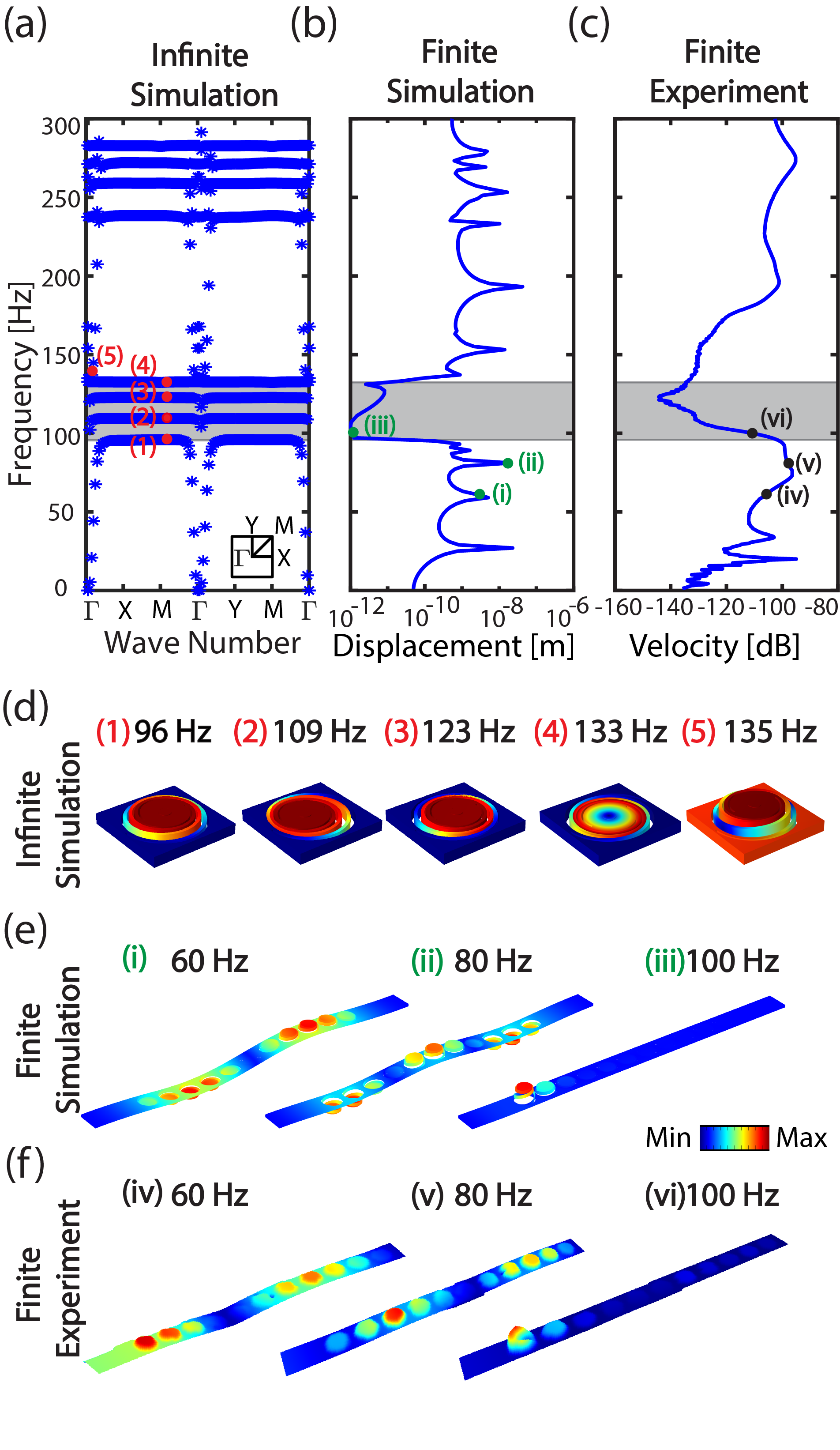
To study the dynamics of our metamaterial, we consider a single unit cell with two concentric Archimedean spiral cuts and an embedded cylindrical permanent magnet at its center. We assume an infinite repetition of the unit cell in space by implementing a Bloch solution Deymier (2013) in the form: , where is the Bloch displacement vector, x is the position vector, is the wave number, is the frequency, and is time. By employing the Bloch solution, we write the dispersion relation as an eigenvalue problem in the form: , where M, K are the mass and stiffness matrices, respectively. We obtain the dispersion curves, correlating frequency and wavenumber, for our unit cell by solving the formulated eigenvalue problem. We use the finite element method to calculate the dispersion curves (Fig. 2 (a)) utilizing COMSOL multi-physics version 6.0. The dispersion curves show a complete (i.e., in all wave propagation directions) band gap between 96 Hz and 135 Hz, or 34% band gap (gray highlighted region in Figure 2 (a-c)). The mode shapes at the edges of the band gap correspond to out-of-plane displacement profiles for the center of the unit cell (Fig.2 (d)). Within the highlighted band gap frequency range, there exist three transmission branches (at 109, 123, and 133 Hz) corresponding to in-plane modes (Fig.2 (d)). The position of the band gap within the frequency spectrum is a function of the unit cell design parameters Foehr et al. (2018); Bilal et al. (2020); Kheybari et al. (2022b). For example, decreasing the width of the spiral cuts, while keeping all other parameters fixed, increases the band-gap’s central frequency (Fig.S2). Such decrease in the width of the cut, increases the thickness of the spiraling arms, which in turn increase the arms’ stiffness and vice-versa. However, such change in unit cell parameters is permanent, i.e., once fabricated, the unit cell design can not be altered. An alternative route to achieve tunability of the band gap frequency range is to selectively add dynamically controllable stiffness to the modes at the edge of the band gap. Given the displacement profile of the mode shapes at the edge of the gap, an added stiffness to the center of the spirals, changes the frequency of the mode and therefore shifts the edge of the band gap. We achieve such shift through programming the surrounding magnetic field both in time and space.
To verify our band structure calculations, using the infinite unit cell model (i.e., with Bloch periodic boundary conditions), we numerically simulate a meta-structure composed of a finite number of unit cells. We consider an array of 11 unit cells with fixed-fixed boundary conditions. We apply an out-of-plane harmonic excitation at one end of the metamaterial and record the transmission of the wave at the other end of the metamaterial. The result shows a clear attenuation through the metamaterial at the predicted band gap region as highlighted in gray (Fig.2 (b)). In addition, we examine three vibrational modes of the simulated finite structure inside and outside the band gap frequency range (Fig.2 (e)). The first two modes at 60 and 80 Hz show clear transmission from the left-end to the right-end within the metamaterial (Fig.2 (e)i and ii), while the third mode at 100 Hz shows clear localization of the excited wave on the left end of the metamaterial(Fig.2 (e)iii).
To experimentally validate the numerical simulations of both the infinite and the finite structures, we fabricate a physical prototype of our metamaterial consisting of an array of 11x1 unit cells. We replicate the finite meta-structure simulations experimentally, by harmonically exciting the metamaterial at one-end with a mechanical shaker. We measure the amplitude of the response at the other end of the meta-structure, using a scanning laser vibrometer, as we sweep through different excitation frequencies. The resulting frequency response function (FRF) shows a good agreement with our numerical simulations, particularly at the attenuated band gap region (Fig.2 (c)). Furthermore, we experimentally scan the entire meta-structure at three different excitation frequencies, to visualize the transmission of the wave from the left-end to the right-end. Both scans at 60 and 80 Hz show clear transmission of the wave through the meta-structure from left to right. The third experimental scan at 100 Hz, however, shows a clear localization of the wave at the left-end of the meta-structure (Fig.2 (f); Movies S1-S3).
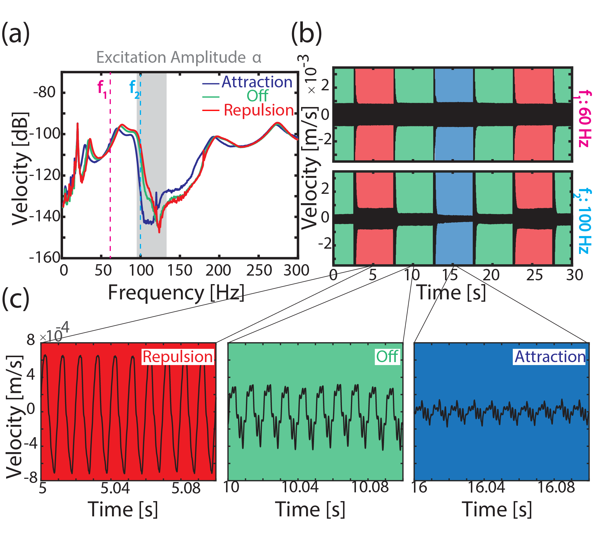
Once fabricated, metamaterial properties are usually fixed. Having the ability to tune their properties in real-time without moving parts could be invaluable for future applications. To test our proposed concept of dynamic tunability in the frequency domain, we harmonically excite the metamaterials in the presence of two different magnetic-field polarizations and record the amplitude of the transmitted elastic waves. We superimpose the measured steady state responses of the metamaterial (FRF) with the electromagnets ON and OFF. We consider both cases when the magnetic field is ON and in repulsion or ON and in attraction relative to the unit cells’ permanent magnets (Fig. 3 (a)). There exists a shift of the band gap frequency due to the presence of the magnetic field. More importantly, we observe a clear difference between the metamaterial’s steady state response in repulsion vs attraction. This difference stems from the inherent asymmetry in the magnetic field as the core of the unit cell is pushed closer or farther away from the electromagnets, which is amplified by the designed geometric asymmetry (top vs bottom) within the unit cell.
In order to characterize the behavior of the metamaterial in the time domain, we keep the harmonic excitation source fixed to a single amplitude (). We then record the transmitted elastic wave through the metamaterial under different magnetic fields for two frequencies = 60 Hz and = 100 Hz. We program the magnetic field to change between OFF, ON-attraction and ON-repulsion every 5 seconds (Fig.3 (b)). On one hand, at , the transmission amplitude is almost constant despite the change in the magnetic field, because is a pass band frequency. On the other hand, at , the transmission is roughly 6 times higher in the case of repulsion than attraction, with the OFF case having an intermediate transmission amplitude (Fig.3 (b)). For both frequencies, , the change between transmission amplitudes, or the transience, takes (Fig S9; Movies S6).
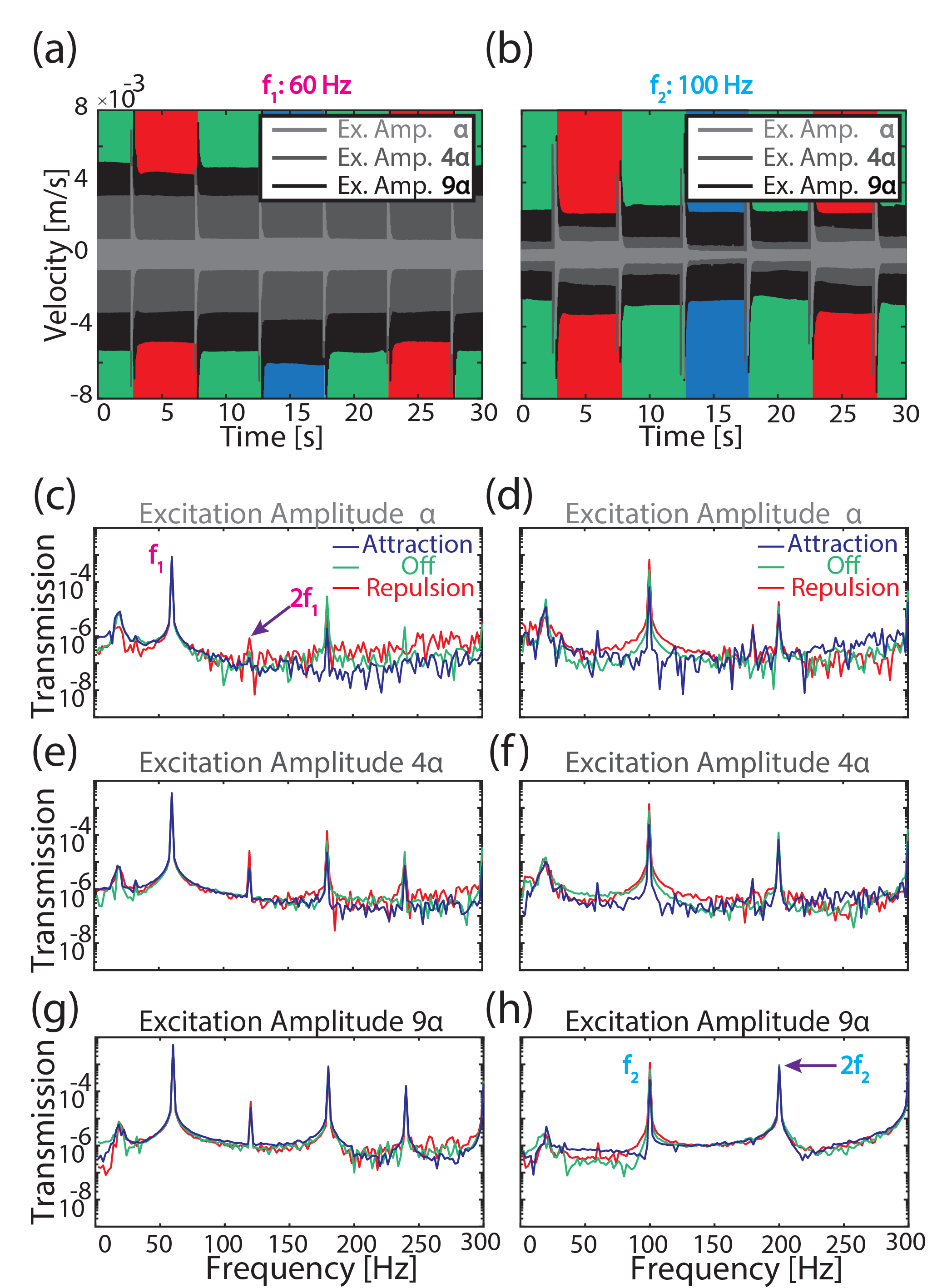
In addition to the change in the amplitude of the transmitted signal at Hz, we observe a change in the transmitted waveform as a function of the magnetic field. To capture the nature of the change in the propagating wave in the time domain, we calculate the transmitted signal’s fast Fourier transform (FFT) at different magnetic-field states (Fig.4d). We note an order of magnitude reduction in the fundamental frequency amplitude between attractive and repulsive magnetic fields at Hz. The amplitude of the second harmonic, Hz, however, experiences less change because falls in a pass band frequency. The amplitude of the fundamental frequency at Hz is not affected by changes in the magnetic field because it is in a pass band; however, the second harmonic of Hz is a stop band frequency that is attenuated. We increase the amplitude of the excitation from to , while shifting the magnetic field from attraction to Off to repulsion every 5 seconds. At both and , we superimpose the transmitted time signal for the different excitation amplitudes (Fig.4 (a-b)). At an excitation amplitude of , the metamaterial can still effectively attenuate the excited wave with the magnetic field ON-attraction vs ON-repulsion. When the excitation amplitude approaches , the transmitted signal’s amplitude loses sensitivity to changes in the magnetic field, and the wave propagates at similar amplitudes at the band gap frequency Hz, whether the magnetic field is ON or OFF. The FFT of the transmitted wave at 100 Hz shows that the amplitudes of both the fundamental excitation frequency and its second harmonic are comparable. In other words, the metamaterial can block a second-harmonic-generated frequency, without affecting the fundamental frequency (Fig.4c,e, and g). Furthermore, with very large excitation amplitudes, the metamaterial can attenuate the fundamental frequency to a level below the generated second harmonic (Fig.4h).
In this study we propose an on-the-fly reprogrammable metamaterial that can control elastic waves without any moving parts. The metamaterial can be tuned in frequency and time, and the tuning is reversible. The study includes numerical and experimental analysis of the metamaterial, showing that the frequency bandgap can be shifted with a magnetic field and the transmission can be controlled by programming the metamaterial in time. Furthermore, the metamaterial can selectively attenuate certain spectral components beyond the excited fundamental frequency. Our metamaterial could be utilized in many potential applications in advanced acoustic devices.
Methods
We fabricate the metamaterial using a laser cuter (Full spectrum, pro-series-PS 24). The lattice constant of the fabricated metamaterial is . The metamaterials are fabricated out of acrylic sheets with Young’s modulus , density , and Poisson’s ratio . The fabricated unit cells have asymmetric profile along their thickness. The spiral cutting width, , varies from top () to bottom () with average cutting width of . The embedded magnets at the center of each unit cell are cylindrical neodymium magnets with a diameter. An array of electromagnets (type: kk-P20/25, DC12V Kaka Electric) was placed underneath the metamaterial sample. All the electromagnets were connected in parallel to an Arduino circuit powered by a DC supply (type: LW PS-3010DF). The distance between the metamaterial sample and the electromagnets in the OFF state is . We excite the metamaterial with a mechanical shaker (type: Brüel & Kjær 4180) at one end, while the other end is fixed. We measure the response of the metamaterial by a scanning laser Doppler vibrometer (Polytech-PSV-500).
References
- Lu et al. (2009) M.-H. Lu, L. Feng, and Y.-F. Chen, Materials today 12, 34 (2009).
- Maldovan (2013) M. Maldovan, Nature 503, 209 (2013).
- Hussein et al. (2014) M. I. Hussein, M. J. Leamy, and M. Ruzzene, Applied Mechanics Reviews 66 (2014).
- Cummer et al. (2016) S. A. Cummer, J. Christensen, and A. Alù, Nature Reviews Materials 1, 1 (2016).
- Bilal and Hussein (2013) O. R. Bilal and M. I. Hussein, Applied Physics Letters 103, 111901 (2013).
- Deymier (2013) P. A. Deymier, Acoustic metamaterials and phononic crystals, Vol. 173 (Springer Science & Business Media, 2013).
- Yang et al. (2010) Z. Yang, H. Dai, N. Chan, G. Ma, and P. Sheng, Applied Physics Letters 96, 041906 (2010).
- Mei et al. (2012) J. Mei, G. Ma, M. Yang, Z. Yang, W. Wen, and P. Sheng, Nature communications 3, 1 (2012).
- Ding et al. (2010) W. Ding, D. Tang, Y. Liu, L. Chen, and X. Sun, Applied Physics Letters 96, 111114 (2010).
- Li et al. (2019) G.-H. Li, Y.-Z. Wang, and Y.-S. Wang, Scientific reports 9, 1 (2019).
- Wang et al. (2023) T.-T. Wang, Y.-F. Wang, Z.-C. Deng, V. Laude, and Y.-S. Wang, Composite Structures 303, 116355 (2023).
- Torrent and Sánchez-Dehesa (2007) D. Torrent and J. Sánchez-Dehesa, New journal of physics 9, 323 (2007).
- Yang et al. (2004) S. Yang, J. H. Page, Z. Liu, M. L. Cowan, C. T. Chan, and P. Sheng, Physical review letters 93, 024301 (2004).
- Li et al. (2012) Y. Li, B. Liang, X. Tao, X.-f. Zhu, X.-y. Zou, and J.-c. Cheng, Applied Physics Letters 101, 233508 (2012).
- Cummer and Schurig (2007) S. A. Cummer and D. Schurig, New journal of physics 9, 45 (2007).
- Torrent and Sánchez-Dehesa (2008) D. Torrent and J. Sánchez-Dehesa, New Journal of Physics 10, 063015 (2008).
- Cummer et al. (2008) S. A. Cummer, B.-I. Popa, D. Schurig, D. R. Smith, J. Pendry, M. Rahm, and A. Starr, Physical review letters 100, 024301 (2008).
- Pennec et al. (2004) Y. Pennec, B. Djafari-Rouhani, J. Vasseur, A. Khelif, and P. A. Deymier, Physical Review E 69, 046608 (2004).
- Zhu and Semperlotti (2013) H. Zhu and F. Semperlotti, AIP Advances 3, 092121 (2013).
- Liao et al. (2021) G. Liao, C. Luan, Z. Wang, J. Liu, X. Yao, and J. Fu, Journal of Physics D: Applied Physics 54, 335301 (2021).
- Boechler et al. (2010) N. Boechler, G. Theocharis, S. Job, P. G. Kevrekidis, M. A. Porter, and C. Daraio, Physical review letters 104, 244302 (2010).
- Lee et al. (2012) K. Lee, M. K. Jung, and S. H. Lee, Physical Review B 86, 184302 (2012).
- Langfeldt et al. (2016) F. Langfeldt, J. Riecken, W. Gleine, and O. von Estorff, Journal of Sound and Vibration 373, 1 (2016).
- Wang et al. (2014) P. Wang, F. Casadei, S. Shan, J. C. Weaver, and K. Bertoldi, Physical review letters 113, 014301 (2014).
- Kheybari et al. (2022a) M. Kheybari, C. Daraio, and O. R. Bilal, Applied Physics Letters 121, 081702 (2022a).
- Roshdy et al. (2023) M. Roshdy, T. Chen, S. Nakhmanson, and O. R. Bilal, Extreme Mechanics Letters , 101966 (2023).
- Zhang et al. (2022) K. Zhang, L. Qi, P. Zhao, C. Zhao, and Z. Deng, Composite Structures , 116421 (2022).
- Kheybari et al. (2022b) M. Kheybari, Z. Wang, H. Xu, and O. R. Bilal, Extreme Mechanics Letters 52, 101620 (2022b).
- Airoldi and Ruzzene (2011) L. Airoldi and M. Ruzzene, New Journal of Physics 13, 113010 (2011).
- Sugino et al. (2017) C. Sugino, S. Leadenham, M. Ruzzene, and A. Erturk, Smart Materials and Structures 26, 055029 (2017).
- Chen et al. (2013) S.-B. Chen, J.-H. Wen, G. Wang, and X.-S. Wen, Chinese Physics B 22, 074301 (2013).
- Casadei et al. (2012) F. Casadei, T. Delpero, A. Bergamini, P. Ermanni, and M. Ruzzene, Journal of Applied Physics 112, 064902 (2012).
- Hou and Assouar (2015) Z. Hou and B. M. Assouar, Applied Physics Letters 106, 251901 (2015).
- Sugino et al. (2020) C. Sugino, M. Ruzzene, and A. Erturk, Physical Review Applied 13, 061001 (2020).
- Yi et al. (2020) K. Yi, G. Matten, M. Ouisse, E. Sadoulet-Reboul, M. Collet, and G. Chevallier, Smart Materials and Structures 29, 035005 (2020).
- Celli et al. (2018) P. Celli, W. Zhang, and S. Gonella, Physical Review Applied 9, 014014 (2018).
- Alshaqaq et al. (2022) M. Alshaqaq, C. Sugino, and A. Erturk, Physical Review Applied 17, L021003 (2022).
- Degraeve et al. (2014) S. Degraeve, C. Granger, B. Dubus, J. O. Vasseur, M. Pham Thi, and A.-C. Hladky-Hennion, Journal of applied Physics 115, 194508 (2014).
- Li et al. (2022) J. Li, P. Yang, and M. Xia, Journal of Intelligent Material Systems and Structures 33, 2520 (2022).
- Xiao et al. (2015) S. Xiao, G. Ma, Y. Li, Z. Yang, and P. Sheng, Applied Physics Letters 106, 091904 (2015).
- Ma et al. (2018) G. Ma, X. Fan, P. Sheng, and M. Fink, Proceedings of the National Academy of Sciences 115, 6638 (2018).
- Wang et al. (2016) Z. Wang, Q. Zhang, K. Zhang, and G. Hu, Advanced materials 28, 9857 (2016).
- Chen et al. (2016) Z. Chen, C. Xue, L. Fan, S.-y. Zhang, X.-j. Li, H. Zhang, and J. Ding, Scientific reports 6, 1 (2016).
- Yang et al. (2017) T. Yang, Z.-G. Song, E. Clerkin, Y.-W. Zhang, J.-H. Sun, Y.-S. Su, L.-Q. Chen, and P. Hagedorn, AIP Advances 7, 095323 (2017).
- Haghpanah et al. (2016) B. Haghpanah, H. Ebrahimi, D. Mousanezhad, J. Hopkins, and A. Vaziri, Advanced Engineering Materials 18, 643 (2016).
- Salari-Sharif et al. (2019) L. Salari-Sharif, B. Haghpanah, A. G. Izard, M. Tootkaboni, and L. Valdevit, Physical Review Applied 11, 024062 (2019).
- Liu et al. (2019) H. Liu, Q. Zhang, K. Zhang, G. Hu, and H. Duan, Advanced Science 6, 1900401 (2019).
- Gao et al. (2023) W. Gao, B. Yang, Y. Hong, K. Guo, P. Sun, and J. Sun, Mechanical Systems and Signal Processing 185, 109756 (2023).
- Bilal et al. (2017a) O. R. Bilal, A. Foehr, and C. Daraio, Proceedings of the National Academy of Sciences 114, 4603 (2017a).
- Bilal et al. (2017b) O. R. Bilal, A. Foehr, and C. Daraio, Advanced materials 29, 1700628 (2017b).
- Robillard et al. (2009) J.-F. Robillard, O. B. Matar, J. Vasseur, P. A. Deymier, M. Stippinger, A.-C. Hladky-Hennion, Y. Pennec, and B. Djafari-Rouhani, Applied Physics Letters 95, 124104 (2009).
- Vasseur et al. (2011) J. Vasseur, O. B. Matar, J. Robillard, A.-C. Hladky-Hennion, and P. A. Deymier, AIP advances 1, 041904 (2011).
- Allein et al. (2016) F. Allein, V. Tournat, V. Gusev, and G. Theocharis, Applied Physics Letters 108, 161903 (2016).
- Chen et al. (2014) X. Chen, X. Xu, S. Ai, H. Chen, Y. Pei, and X. Zhou, Applied Physics Letters 105, 071913 (2014).
- Zhao et al. (2017) J. Zhao, X. Li, Y. Wang, W. Wang, B. Zhang, and X. Gai, The Journal of the Acoustical Society of America 141, 840 (2017).
- Guell Izard and Valdevit (2020) A. Guell Izard and L. Valdevit, Advanced Engineering Materials 22, 1901019 (2020).
- Zhang et al. (2021) K. Zhang, W. Jiao, and S. Gonella, Physical Review B 104, L020301 (2021).
- Caleap and Drinkwater (2014) M. Caleap and B. W. Drinkwater, Proceedings of the National Academy of Sciences 111, 6226 (2014).
- Li et al. (2014) F. Li, P. Anzel, J. Yang, P. G. Kevrekidis, and C. Daraio, Nature communications 5, 1 (2014).
- Boechler et al. (2011) N. Boechler, G. Theocharis, and C. Daraio, Nature materials 10, 665 (2011).
- Chuang et al. (2019) K.-C. Chuang, X.-F. Lv, and Y.-H. Wang, Journal of Applied Physics 125, 055101 (2019).
- Hu et al. (2018) H.-L. Hu, J.-W. Peng, and C.-Y. Lee, Vibration 1, 81 (2018).
- Candido de Sousa et al. (2018) V. Candido de Sousa, D. Tan, C. De Marqui Jr, and A. Erturk, Applied Physics Letters 113, 143502 (2018).
- Lv et al. (2020) X.-F. Lv, S.-F. Xu, Z.-L. Huang, and K.-C. Chuang, Physics Letters A 384, 126056 (2020).
- Gliozzi et al. (2020) A. S. Gliozzi, M. Miniaci, A. Chiappone, A. Bergamini, B. Morin, and E. Descrovi, Nature communications 11, 2576 (2020).
- Li et al. (2021) B. Li, C. Zhang, F. Peng, W. Wang, B. D. Vogt, and K. Tan, Journal of Materials Chemistry C 9, 1164 (2021).
- Sepehri et al. (2021) S. Sepehri, M. M. Mashhadi, and M. M. S. Fakhrabadi, Physica Scripta 96, 125527 (2021).
- Song and Shen (2022) Y. Song and Y. Shen, Smart Materials and Structures 31, 055019 (2022).
- Chen et al. (2018) S. Chen, Y. Fan, Q. Fu, H. Wu, Y. Jin, J. Zheng, and F. Zhang, Applied Sciences 8, 1480 (2018).
- Zangeneh-Nejad and Fleury (2019) F. Zangeneh-Nejad and R. Fleury, Reviews in Physics 4, 100031 (2019).
- Kumar and Pueh Lee (2019) S. Kumar and H. Pueh Lee, International Journal of Applied Mechanics 11, 1950081 (2019).
- Ji and Huber (2021) G. Ji and J. Huber, Applied Materials Today , 101260 (2021).
- Xia et al. (2022) X. Xia, C. M. Spadaccini, and J. R. Greer, Nature Reviews Materials 7, 683 (2022).
- Foehr et al. (2018) A. Foehr, O. R. Bilal, S. D. Huber, and C. Daraio, Physical review letters 120, 205501 (2018).
- Bilal et al. (2020) O. R. Bilal, A. Foehr, and C. Daraio, Journal of Applied Mechanics 87, 071009 (2020).
Supporting Information:
Harnessing asymmetry to reprogram nonlinear metamaterials on-the-fly with no moving parts
I Unit cell analysis
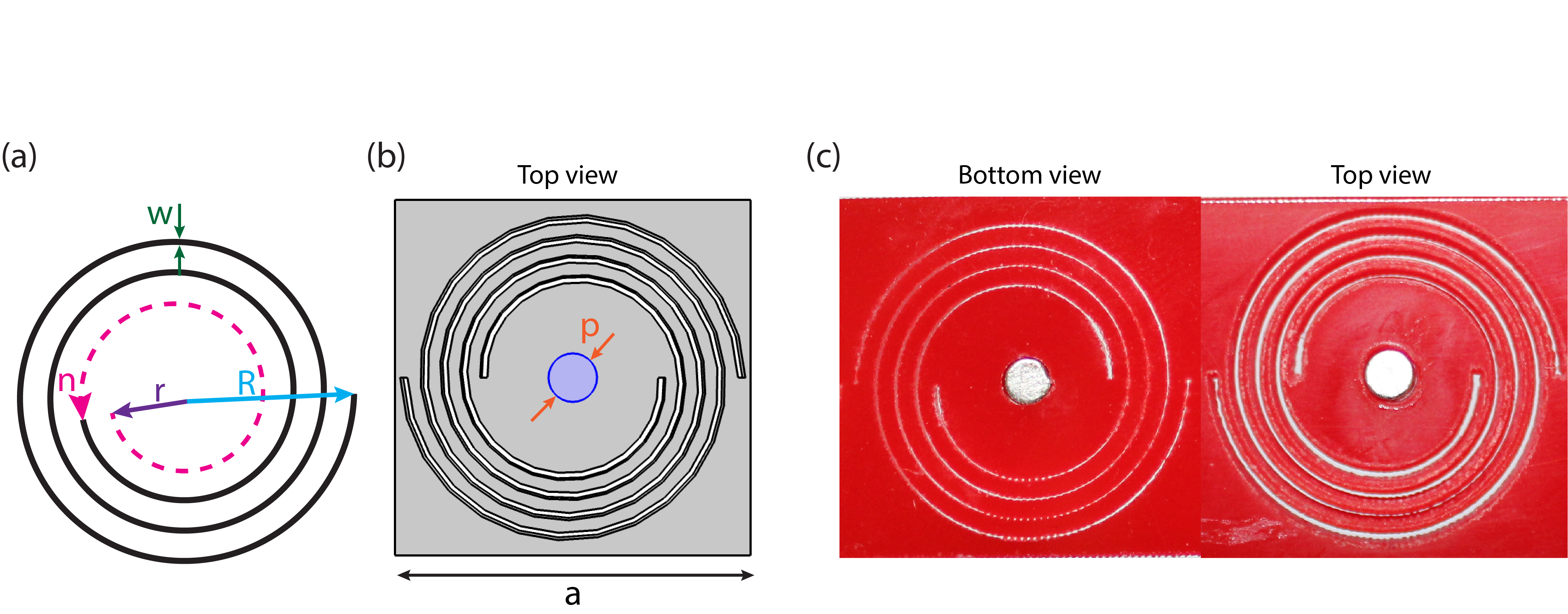
The unit cell is composed of two symmetric cuts in the shape of concentric Archimedean spirals. The equation of the spiral can be written in polar coordinates Foehr et al. (2018) as , where is the inner radius, is the outer radius, is the number of turns, is the lattice constant, is the cutting width of spirals (average of both bottom and top cutting width), and is a diameter of the permanent magnet (Fig.S1 a-b). We fabricate the metamaterial using laser cutting. Despite the symmetric design of the unit cell, the spiraling cuts have asymmetric profiles in the thickness direction, meaning the cutting width of the spirals varies from the top to the bottom surface of the metamaterial(Fig.S1 c)
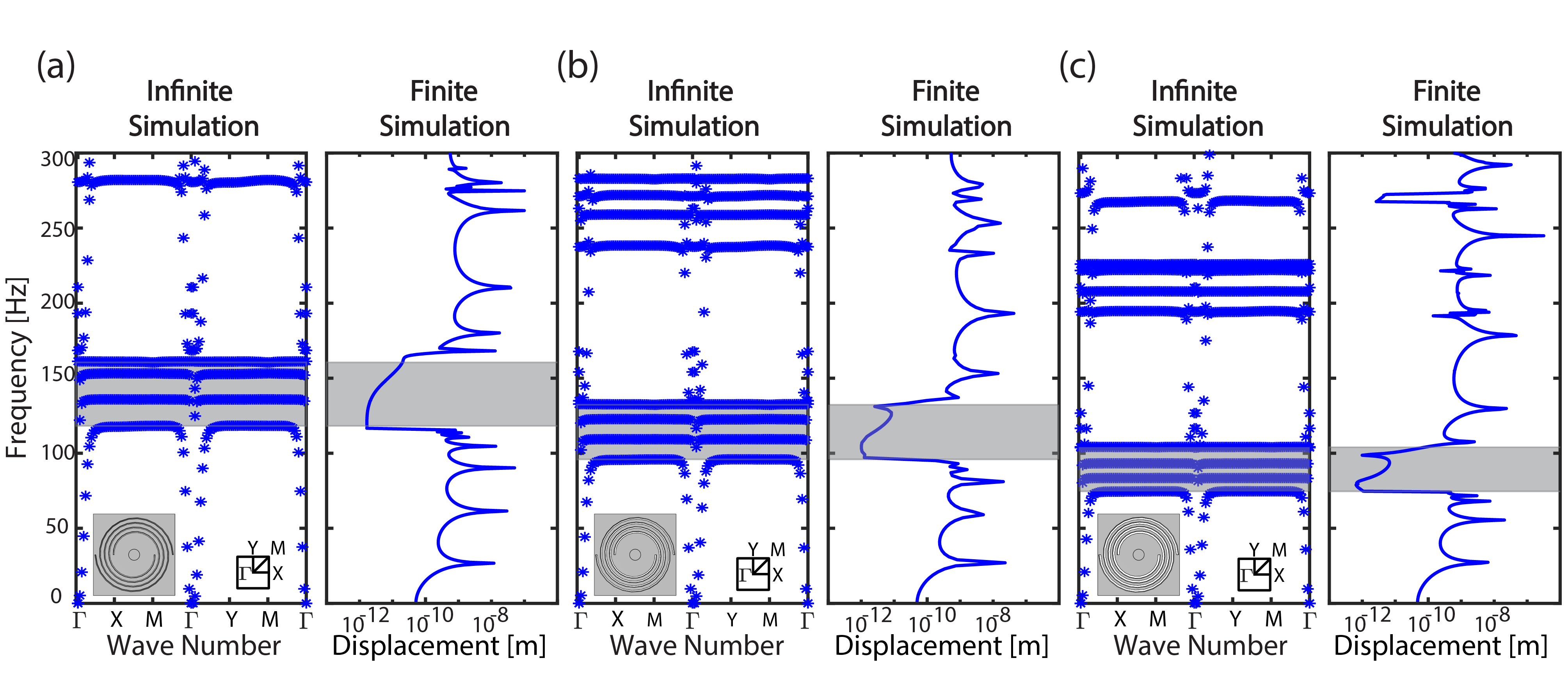
The position of the band gap (BG) within the frequency spectrum is a function of the unit cell design parameters, including the cutting width of the spiral. To study the influence of the unit cell parameters on the BG, we consider a symmetric unit cell with different cutting width, while keeping all other parameters fixed. We compute the dispersion curves for three unit cell with cutting width , and . Indeed, as the cutting width increases the BG frequency decreases. Such decrease in frequency is a result of the reduction of the effective stiffness of the unit cell core. To confirm our infinite model calculations, we numerically simulate a finite structure made out of 11 unit cells. We excite the finite structure at one end and record its transmission at the other end. The resulting frequency response functions show a clear shift in the attenuated frequency ranges as predicted by the infinite unit cell model (Fig.S2 a-c).
II symmetric vs asymmetric unit cell analysis
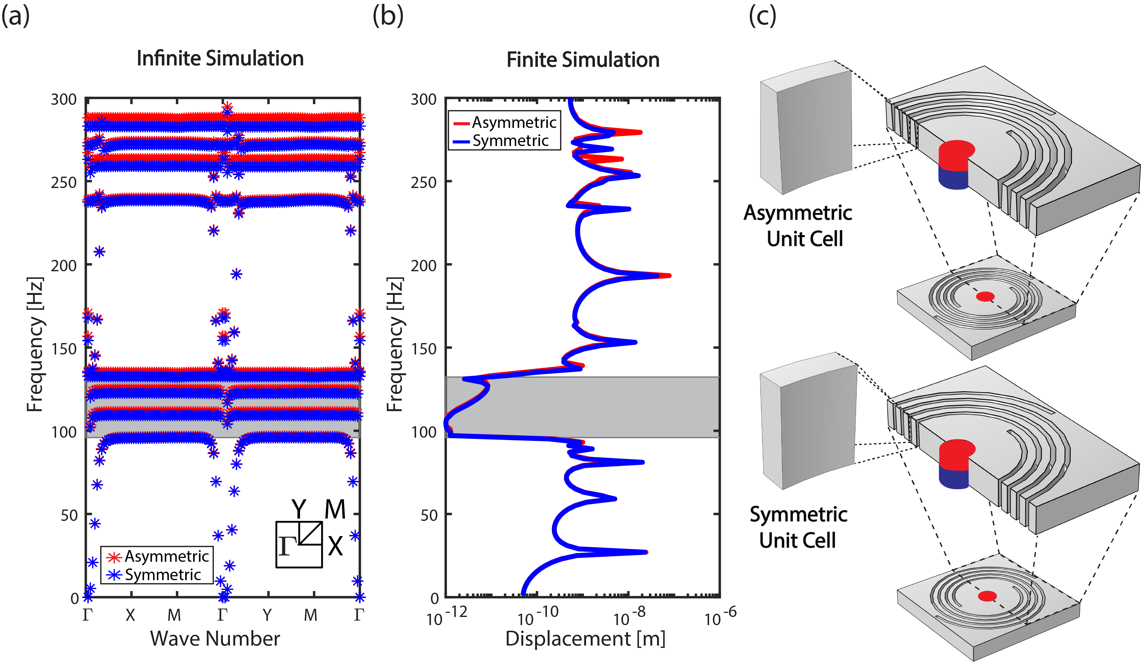
Next, we consider the influence of unit cell symmetry on the properties of our metamaterials. We start by comparing the dispersion curves of a symmetric and an asymmetric unit cells. For the symmetric unit cell, the spiral cut has a width of , while the asymmetric unit cell has top surface cut of () and bottom surface cut (). We choose and such that the average is equivalent to the symmetric unit cell cutting width (Fig.S3 c). The resulting band structures show very similar behavior at low frequency, however as the frequency increases, the two band diagrams start to deviate from each other as more complex modes start to appear (Fig.S3 a). To confirm the band structure calculations, we consider a finite structure analysis for both unit cells and compute the frequency response of the metamaterials. At low frequencies, the difference in the frequency response of the two different unit cells is indeed negligible, but as the frequency increases, the difference between the two becomes more clear, in agreement with our band structure analysis (Fig.S3 b).
III One-dimensional vs two-dimensional periodicity
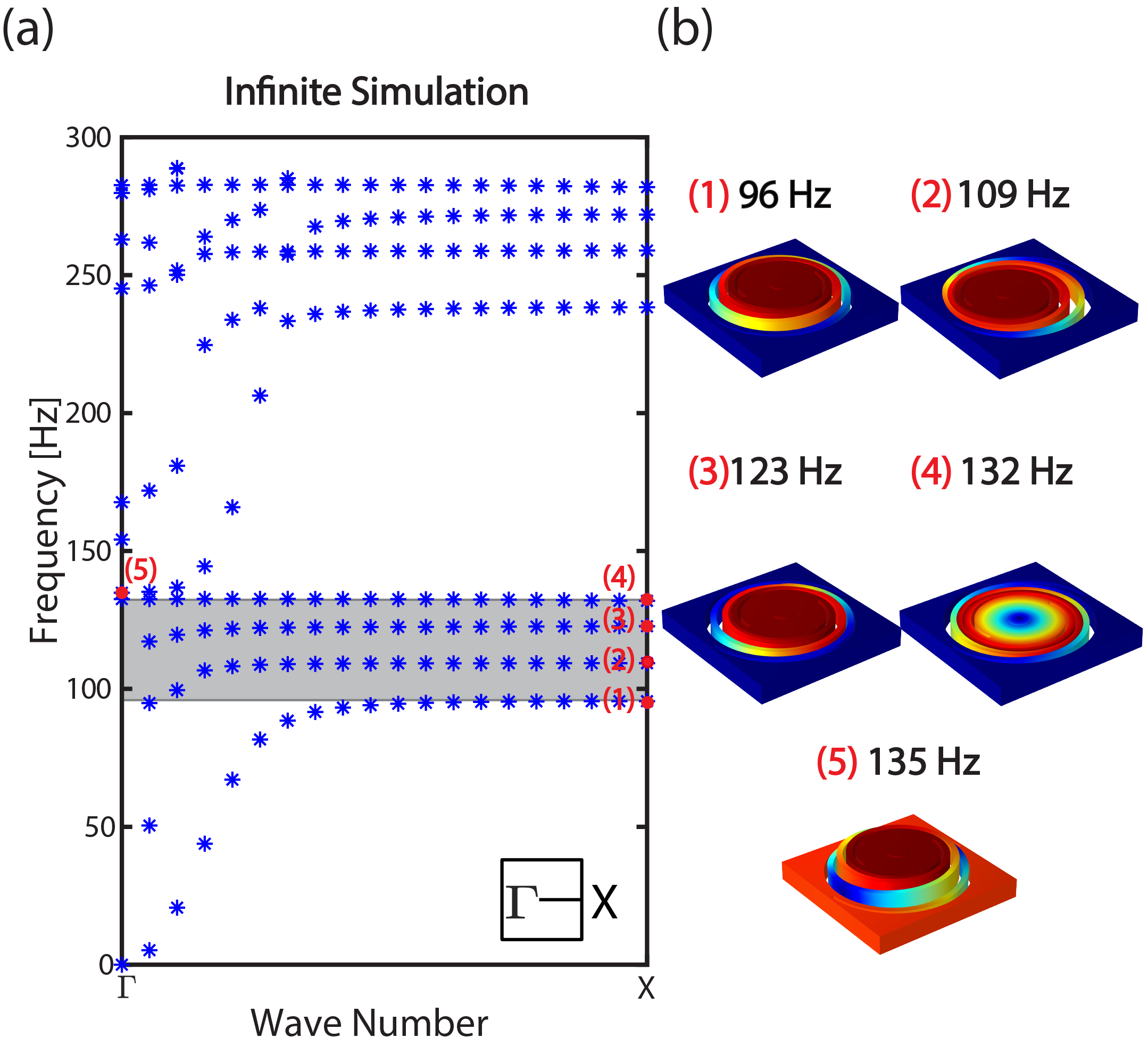
For completeness, we also examine the effect of different types of periodicity on the unit cell band structure. We consider an infinite model with periodicity along only the x-direction (rather than two-direction periodicity along both x and y-directions). In such scenario, we can only calculate the dispersion curve along the path of the irreducible Brillouin zone. The dispersion curves show a band gap (a gray highlighted region in (Fig.S4 a)) that matches the band gap of the two-directions periodic unit cell (Fig.2 (a)). Both mode shapes at the edge of the band gap at 96 Hz and 135 Hz correspond to out-of-plane displacement profiles of the center of the unit cell. Within the band gap frequency range, we also have there transmission branches at 109, 123, and 132 Hz which correspond to in-plane modes (Fig.S4 b).

IV Programming metamaterial in frequency
We examine the response of our metamaterial in the frequency domain under different excitation amplitudes , , and . We start by harmonically exciting one end of the metamaterial sample in the presence of two different magnetic-field polarizations and record the amplitude of the transmitted elastic waves at the other end. At excitation amplitude , we observe a clear shift of the band gap frequency from attraction to repulsion (Fig.S5 a). By increasing the amplitude of the harmonic excitation from to , we still see a shift of the band gap frequency due to the presence of the different magnetic fields, however, the amplitude of the attenuation within the band gap decreases for OFF and ON-repulsion cases (Fig.S5 b-c).
V Programming metamaterial in time
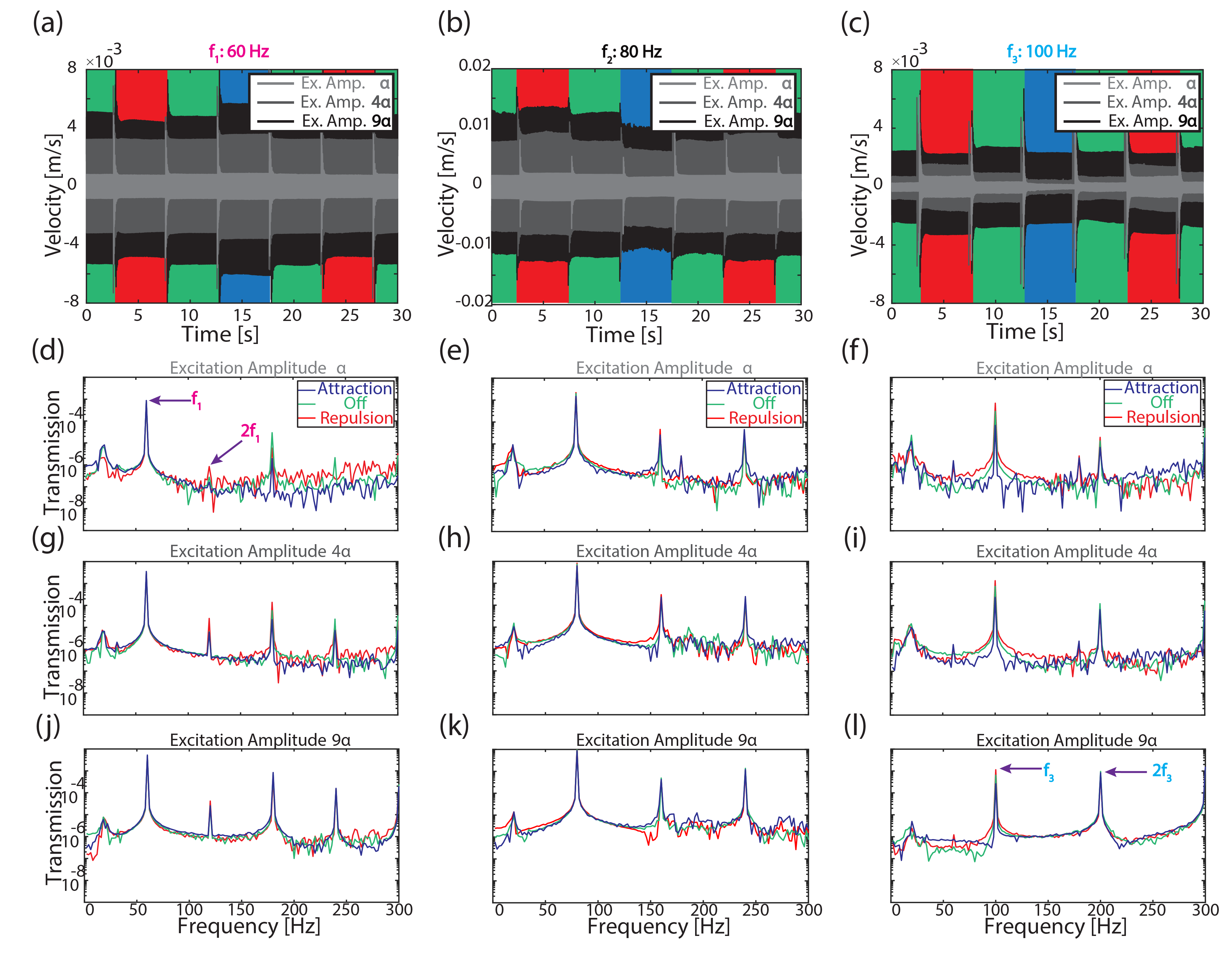
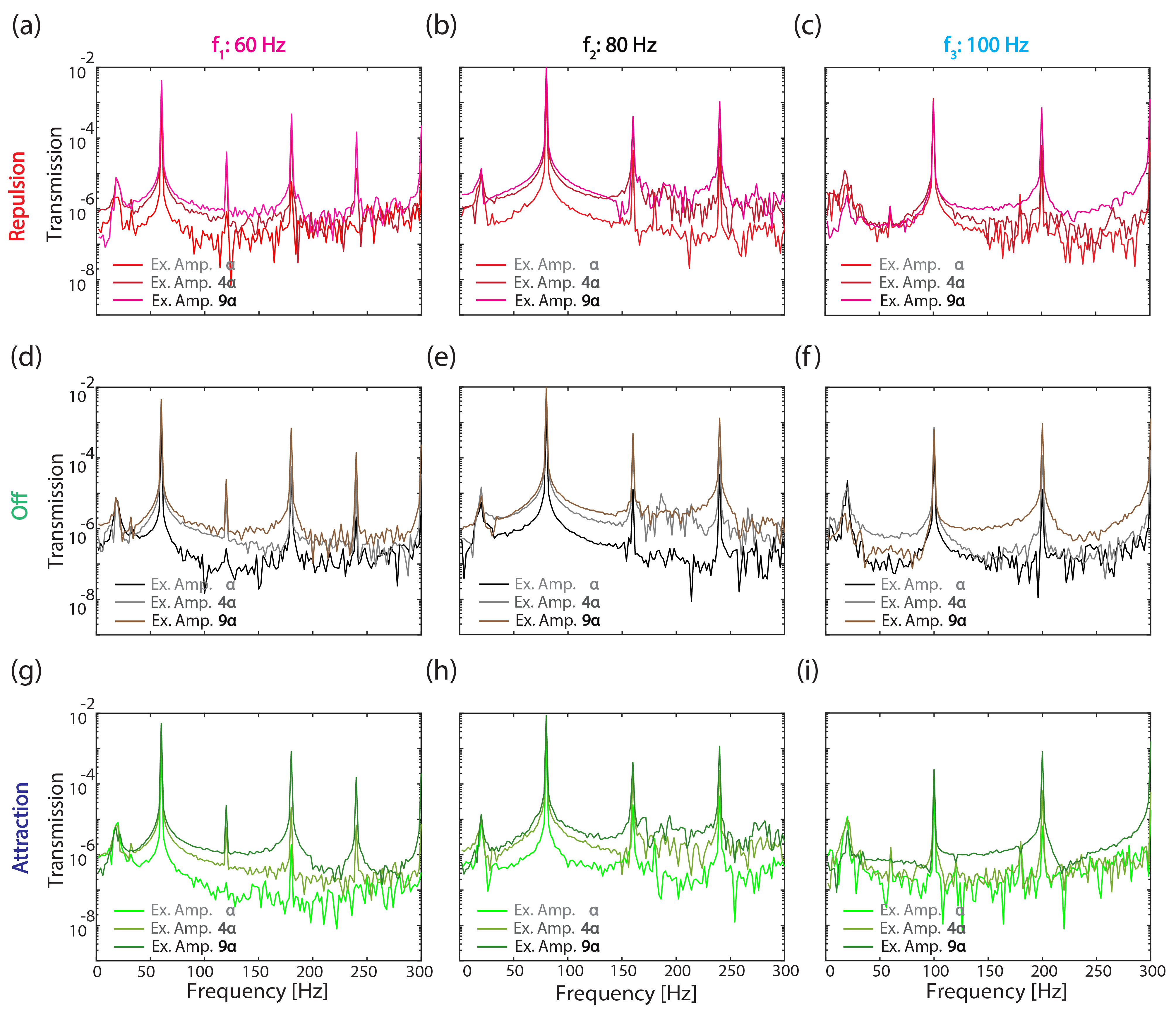
After characterizing the behavior of the metamaterial in the frequency domain we examine the proposed metamaterial in the time domain. First, we program the magnetic field to change between OFF, ON-repulsion, and ON-attraction. Next, we excite one end of the sample with a harmonic excitation and record the transmitted elastic wave through the metamaterial at the other end for two pass band frequencies ( Hz and Hz) and one band gap frequency ( Hz) (Fig.S6 a-c). At frequencies Hz and Hz, the transmission amplitude is almost the same between OFF, ON-repulsion, and ON-attraction because and are pass band frequencies. At the frequency , the transmission amplitude changes by changing the magnetic field between OFF, ON-repulsion, and ON-attraction. For example, the transmission amplitude is 6 times higher in the case of repulsion than attraction. We calculate the transmitted signal’s fast Fourier transform (FFT) for all frequencies. Results show that the amplitude of the fundamental frequencies at Hz and Hz are not affected by changes in the magnetic field from OFF, ON-repulsion to ON-attraction (Fig.S6 d,e). The reason is that both frequencies are in the pass band; however, there is a change at the second harmonic of Hz because it falls in the band gap frequency range (Fig.S6 d). But at the second harmonic of Hz the wave is transmitted because it falls in the pass band frequency (Fig.S6 e). Also, we observe that the amplitude of the second harmonic, Hz shows less change and the reason is that falls in a pass band frequency range (Fig.S6 f). Afterwards, we increase the amplitude of the excitation from to , while still changing the magnetic field polarization every 5 seconds. At the metamaterial can still attenuate the transmitted wave (Fig.S6 i). However, when we increase the amplitude of the excitation from to , the transmitted amplitude is not affected by the change in the magnetic field and the wave propagates at similar amplitudes at the band gap frequency (Fig.S6 l). It should be noted that when the excitation amplitude is , the transmitted amplitude at Hz is higher than that of Hz, which means that the wave is transmitted at higher amplitude at than the second harmonic peak (Fig.S6 k). For better comparing the amplitude of the transmitted wave in the frequency domain, we separate the FFTs based on the magnetic polarizations (Fig.S7).
VI Numerical simulation of the magnetic field
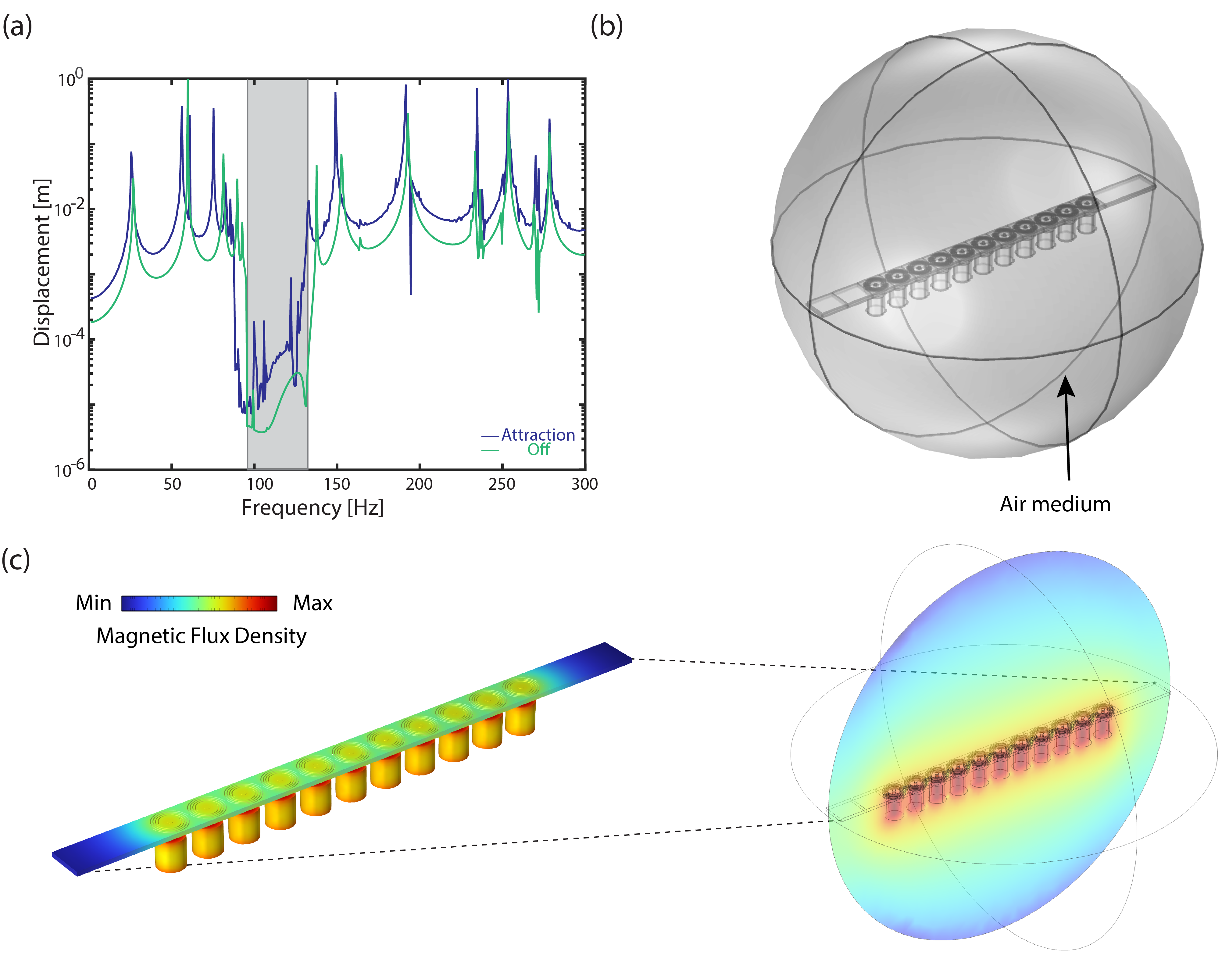
To examine the metamaterial in the frequency domain under the influence of the magnetic field numerically, we utilize COMSOL multi-physics version 6.0. To compute the frequency response function of the transmission in the metamaterial considering the magnetic field effect we use the AC/DC module (magnetic field physics). We consider an array of 11 symmetric unit cells with fixed-fixed boundary conditions. In addition, we model 11 electromagnets and place them underneath the metamaterial sample and surround the sample and electromagnets with an air medium (Fig.S8 b). We apply an out-of-plane harmonic excitation at one end of the metamaterial and record the transmission of the wave at the other end of the metamaterial. We compute the frequency response function of the transmission in the metamaterial for OFF and ON-attraction cases (Fig.S8 a), and the computed magnetic flux density within the medium (Fig.S8 c).
VII Programming time window
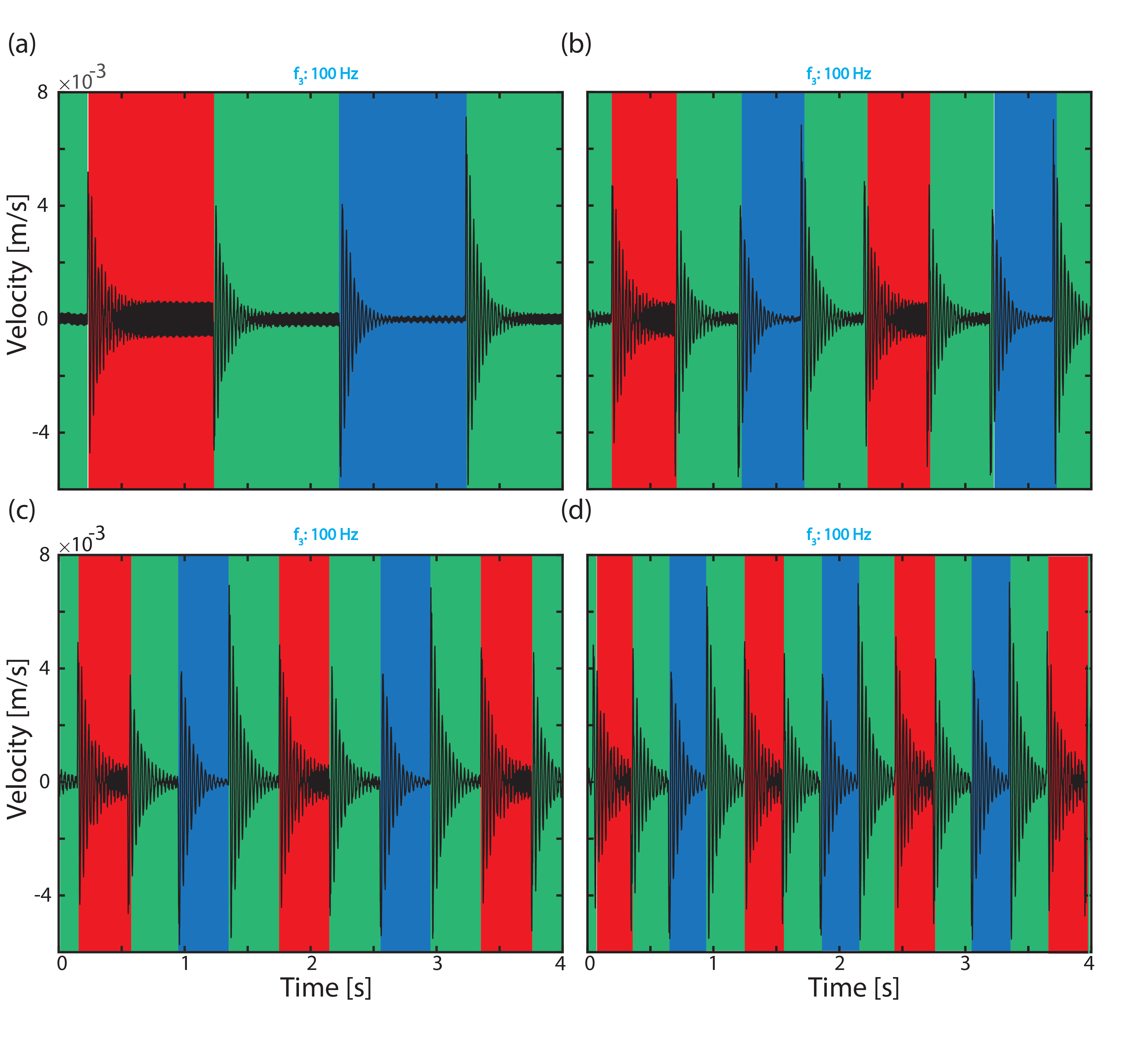
To test the limits of our programming in time, we program the magnetic field to change between OFF, ON-repulsion, and ON-attraction at different time windows (Fig. S9). The excitation frequency is fixed at with an excitation amplitude of . The change in magnetic field happens at windows of 1, 0.5, 0.4 and 0.3 seconds.
VIII Measured static and magnetic forces
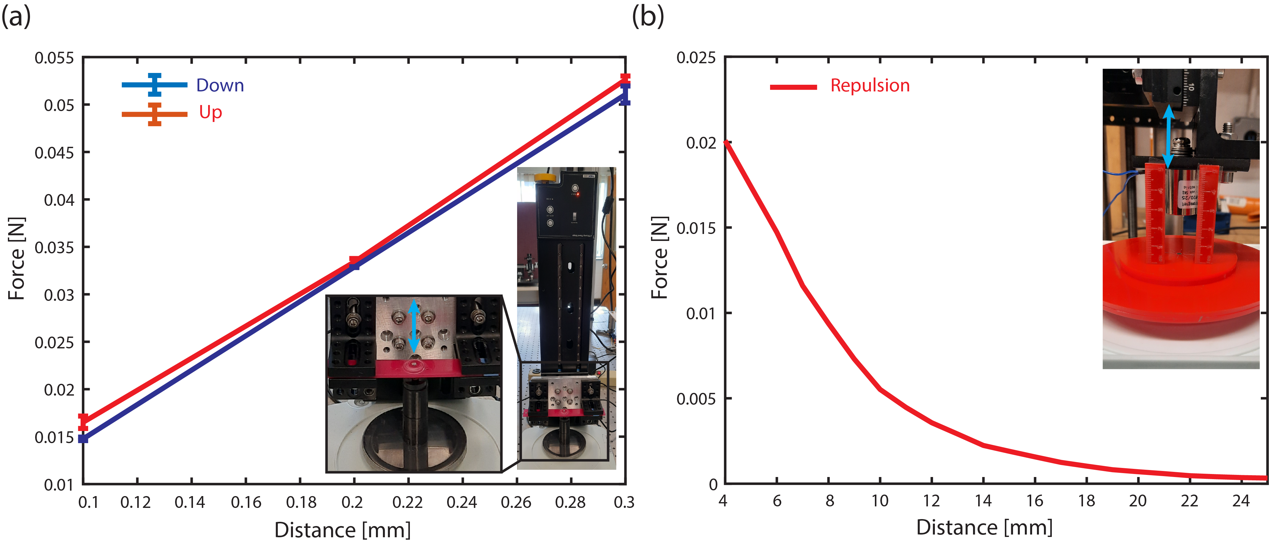
To measure the force, we fabricate a single-unit cell and mount it on a linear translation stage (Thorlabs, LTS-300 Fig.S10 a-inset). We move the sample by an increment of 0.1 mm to measure the force at each step through a load cell (Fig.S10 a). The measured force in both cases shows that the spiral-spring is stiffer when its center goes up and than when its center goes down. This stiffness difference is due to the presence of asymmetrical profiles in the unit cell. Meaning, the cutting width of the spirals varies from the top to the bottom surface of the metamaterial sample as proved by static force measurement.
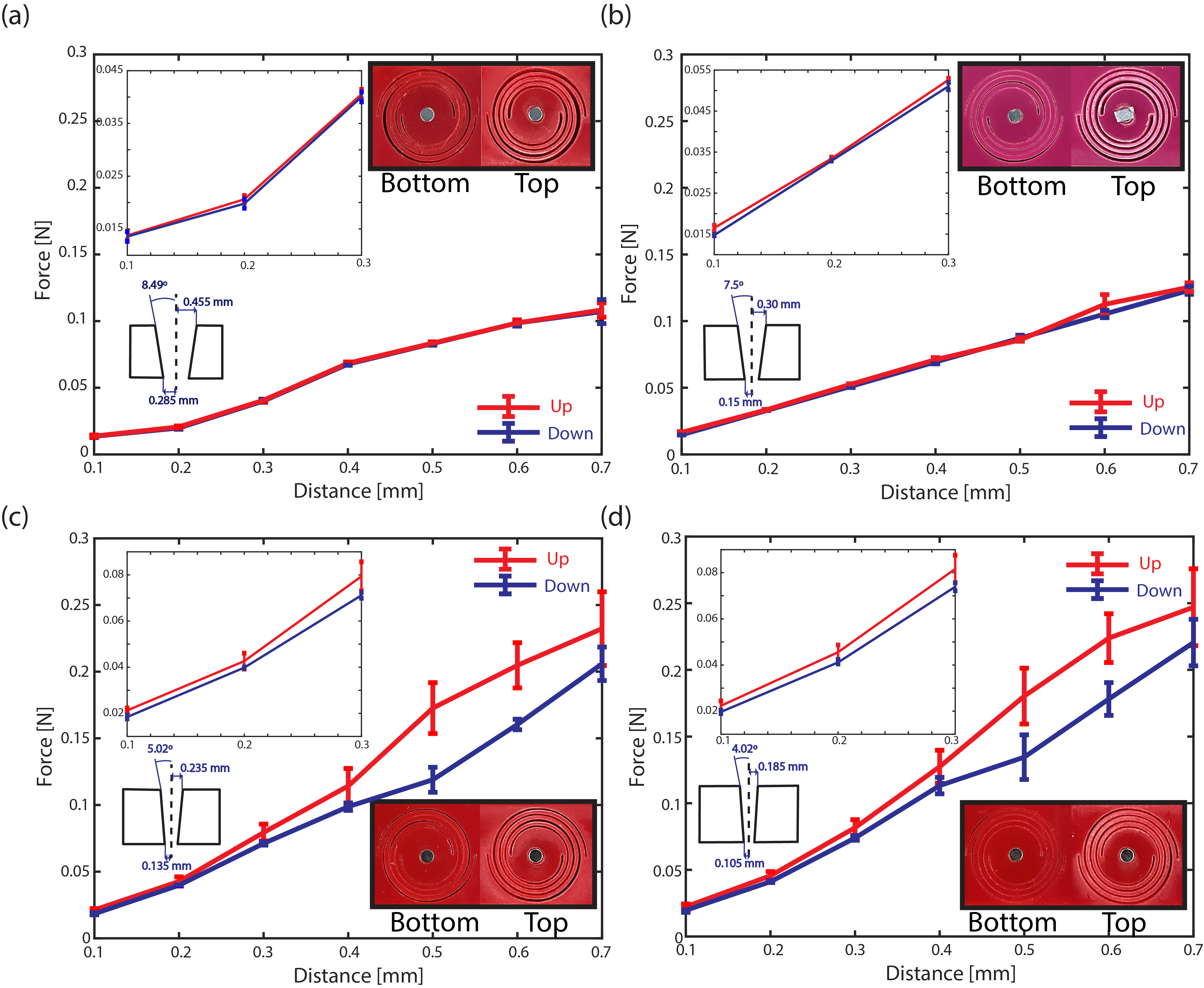
Moreover, we also investigate the asymmetric unit cell profiles and its correlation to plane angles. To do this, we fabricate three more samples with different width of spiral cuts, which varies from top to bottom surface. To measure the angles, we consider the top edge of the surface to the plane (Fig.S11 insets). The results shown in (Fig.S11) are the measured force for the first unit cell with the spiral cutting width, where varies from top () to bottom (), having the plane angle 8.49∘ (Fig.S11 a). The second unit cell with the spiral cutting width, , varies from top () to bottom () with the plane angle 5.02∘ (Fig.S11 c). The third unit cell with the spiral cutting width, , varies from top () to bottom () having the plane angle 4.02∘ (Fig.S11 d). Also, the plane angle for the primary unit cell (Fig.S10 a) and (Fig.S11 b) is 7.5∘. The results show the stiffness differences due to the presence of asymmetrical profiles in the unit cell.
In addition, we characterize the magnetic force between an electromagnetic and a permanent magnet. We fabricate a single unit cell with an embedded magnet at its center. We start incrementally move the electromagnet closer to the magnet with a linear stage from to (Fig.S10 b).
IX Metamaterial quality factor
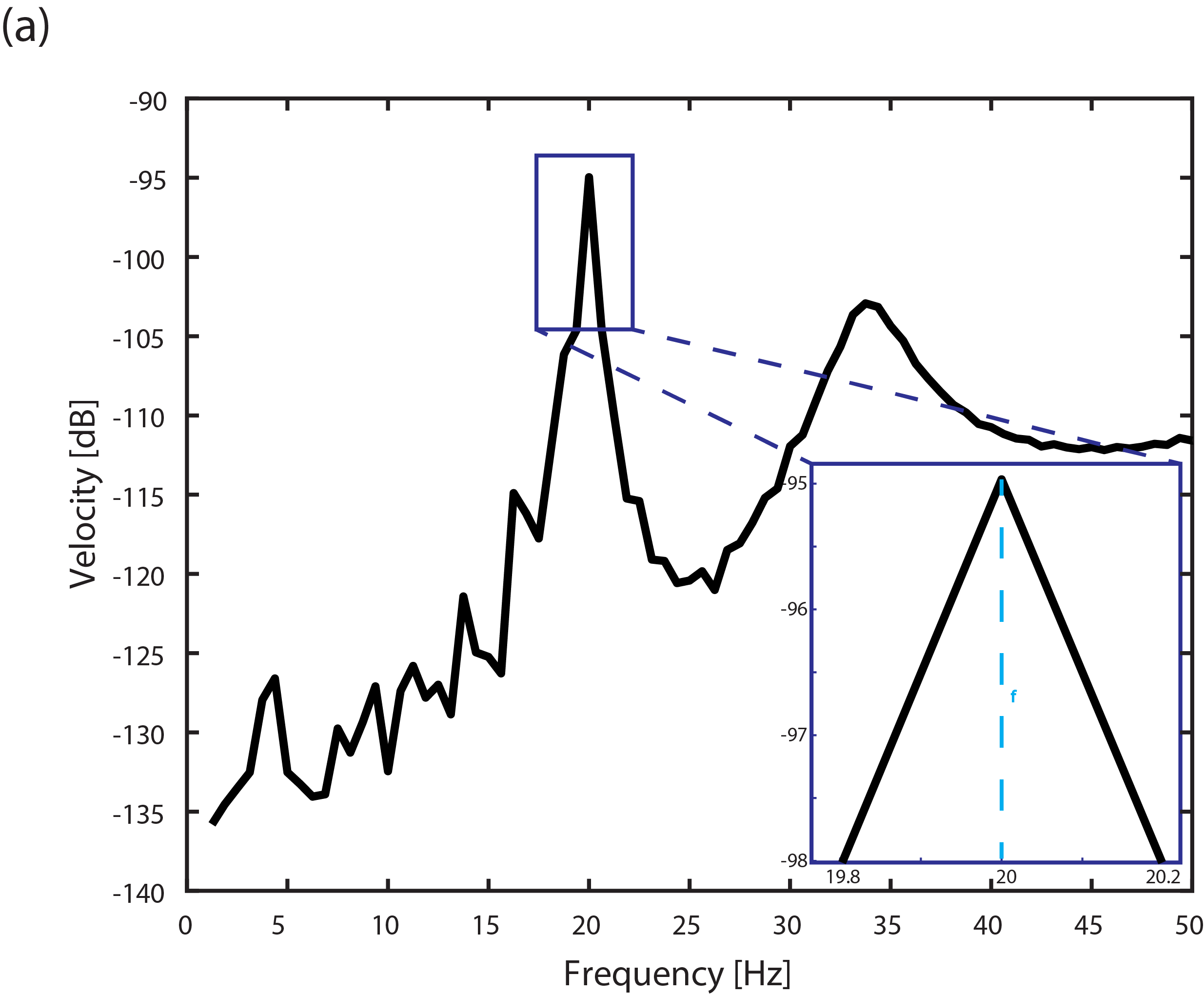
We characterize the quality factor of the material that we use to fabricate the metamaterials, by measuring the resonance amplitude of the sample using a mechanical shaker as a harmonic excitation source. We select the first resonance peak within the frequency response plot (Fig. S12). We calculate which is 50, where is the resonance frequency and is the width of the frequency range.
X Force-displacement simulation
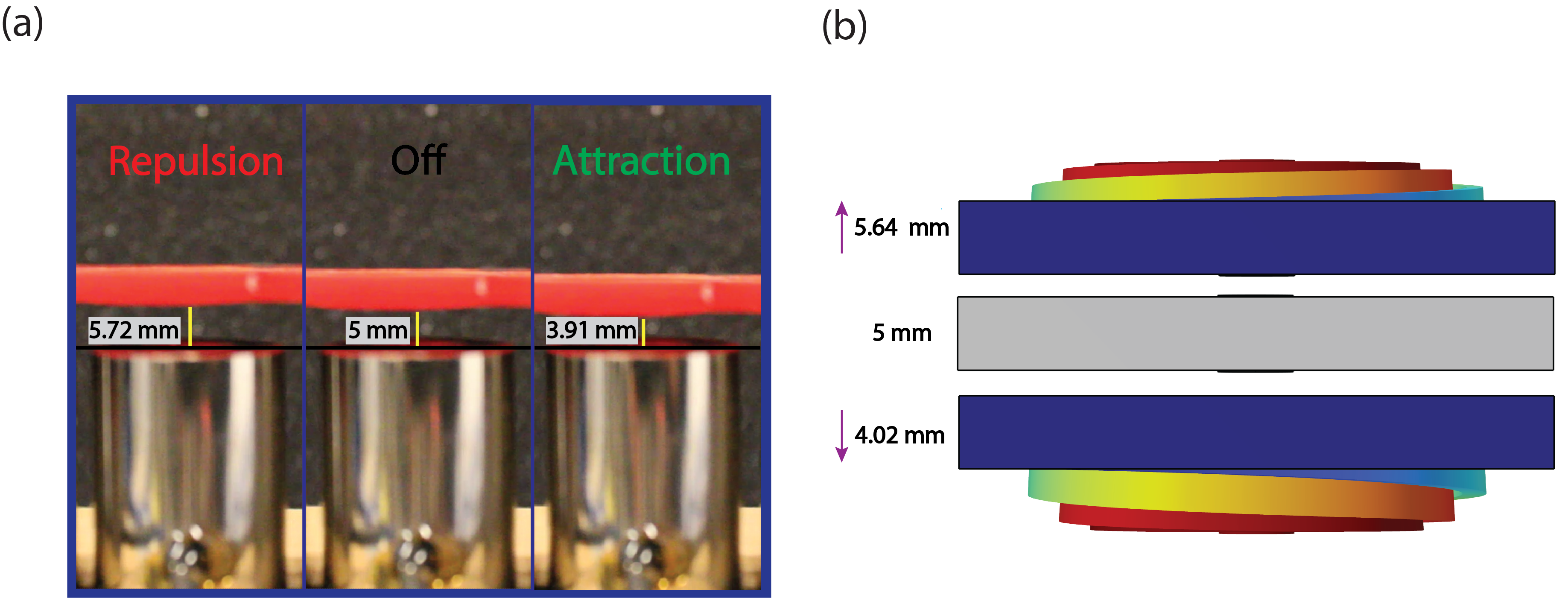
We experimentally measure the distance between the electromagnet and the unit cell for each of the cases (1) magnetic field OFF, (2) ON-repulsion, and (3) ON-attraction. The distance when the magnetic field is OFF = . The displacement for the repulsion () and for attraction is () (Fig. S12 a). We utilize the experimentally obtained values for the reaction forces at the center of the spiral to validate our numerical model. We calculate the displacement of for the case when we apply the force in the up direction (center of spirals goes up) and the displacement of for the case when we apply the force in the down direction (center of spirals goes down). There is a very good agreement between the experimentally obtained static force-displacement values and the numerical ones (Fig. S13 b).
Supplementary movie 1 The movie shows the transmission of the wave through the re-programmable phononic metamaterial at pass band Hz.
Supplementary movie 2 The movie shows the transmission of the wave through the re-programmable phononic metamaterial at pass band Hz.
Supplementary movie 3 The movie shows the attenuation of the wave through the re-programmable phononic metamaterial at band gap Hz.