Observation and formation mechanism of 360∘ domain wall rings in Synthetic Anti-Ferromagnets with interlayer chiral interactions
Abstract
The Interlayer Dzyaloshinskii-Moriya interaction (IL-DMI) chirally couples spins in different ferromagnetic layers of multilayer heterostructures. So far, samples with IL-DMI have been investigated utilizing magnetometry and magnetotransport techniques, where the interaction manifests as a tunable chiral exchange bias field. Here, we investigate the nanoscale configuration of the magnetization vector in a synthetic anti-ferromagnet (SAF) with IL-DMI, after applying demagnetizing field sequences. We add different global magnetic field offsets to the demagnetizing sequence in order to investigate the states that form when the IL-DMI exchange bias field is fully or partially compensated. For magnetic imaging and vector reconstruction of the remanent magnetic states we utilize X-ray magnetic circular dichroism photoemission electron microscopy, evidencing the formation of 360∘ domain wall rings of typically 0.5-3.0 in diameter. These spin textures are only observed when the exchange bias field due to the IL-DMI is not perfectly compensated by the magnetic field offset. From a combination of micromagnetic simulations, magnetic charge distribution and topology arguments, we conclude that a non-zero remanent effective field with components both parallel and perpendicular to the anisotropy axis of the SAF is necessary to observe the rings. This work shows how the exchange bias field due to IL-DMI can lead to complex metastable spin states during reversal, important for the development of novel spintronic devices.
The interlayer Dzyaloshinskii-Moriya interaction (IL-DMI) is an interlayer-mediated antisymmetric exchange interaction observed in multilayer heterostructures, which promotes orthogonal coupling between spins in different magnetic layers Fernández-Pacheco et al. (2019); Han et al. (2019); Vedmedenko et al. (2019); Avci et al. (2021). This coupling mechanism may find interesting applications in 3D nanomagnetism, as it provides the opportunity of inducing chiral magnetic states in a layer controlled by the magnetic state of another.
IL-DMI can be understood as an effective unidirectional magnetic field breaking the symmetry of the reversal process, leading to a chiral exchange bias Han et al. (2019). This exchange bias field has been for instance utilized to achieve field free spin-orbit torque mediated deterministic switching of perpendicularly magnetized thin film systems Huang et al. (2022); Lau et al. (2016); He et al. (2022); Wang et al. (2022); Bekele et al. (2020), as an alternative to exchange bias generated at ferromagnet/anti-ferromagnet interfaces. So far, samples with IL-DMI have been typically investigated with magnetometry and magnetotransport techniques such as the magneto-optical Kerr effect (MOKE) Fernández-Pacheco et al. (2019) and anomalous Hall-effect Han et al. (2019); Wang et al. (2021); Kammerbauer et al. (2022).
Here, the remanent magnetic domain configurations present in a synthetic anti-ferromagnet (SAF) with chiral exchange coupling due to IL-DMI are investigated using X-ray magnetic circular dichroism photo-emission electron microscopy (XMCD-PEEM). The states imaged are obtained after performing a demagnetizing Jang et al. (2012); Dean et al. (2011) process with different external field offsets added to the cycling sequence. By combining multiple XMCD-PEEM projections measured at different azimuthal angles, the magnetization vector is reconstructed, evidencing the formation of 360∘ domain wall (DW) rings. The IL-DMI is found to be key for the stability of these structures, as rings are only observed when the exchange bias IL-DMI field is not fully compensated by the external field offset. Experiments are complemented with micromagnetic simulations, which highlight the importance of the relative orientation of external and demagnetizing dipolar magnetic fields with the in plane anisotropy axis of the sample for the formation of the 360∘ DW rings.
The SAF structure under investigation consists of Si/Ta (4 nm)/Pt (10 nm)/Co (1 nm)/Pt (0.5 nm)/Ru (1 nm)/Pt (0.5 nm)/CoFeB (2 nm)/Pt (2 nm)/Ta (4 nm). The Co layer has strong perpendicular magnetic anisotropy, i.e., it is hard out-of plane (OOP), whereas the CoFeB (Co: 60, Fe: 20, B: 20) has been tailored to show moderately low in-plane (IP) anisotropy by tuning its thickness above its spin reorientation transition, i.e., it is soft IP. In this type of SAFs, a chiral exchange bias due to IL-DMI has been previously observed under measurement of minor IP hysteresis loops on which solely the CoFeB layer reverses while the Co stays fixed in the OOP direction Fernández-Pacheco et al. (2019). Upon reversal of the orientation of the Co layer, the exchange bias changes sign. The unidirectional nature of the effect is manifested by the IP angular dependence of the bias, which shows opposite sign for the two possible directions parallel to the IP anisotropy easy axis (EA), and zero for the directions orthogonal to it.
To investigate the effect of IL-DMI on the domain states forming in these samples, magnetic microscopy measurements were taken at CIRCE Aballe et al. (2015) beamline in ALBA Synchrotron, using XMCD-PEEM (see sketch in figure 1). In this setup, the azimuthal angle of the sample with respect to the X-rays can be modified in the full 360∘ angular range, while the polar angle is fixed to 16∘ with respect to the surface plane, giving large sensitivity to IP components. Both circular polarization images are recorded and combined exploiting XMCD for magnetic contrast Stöhr and Siegmann (2006); Beaurepaire et al. (2001); Yokoyama, Nakagawa, and Takagi (2008), measured at both Fe and Co’s absorption edges at each magnetic state. Prior to the experiments, 50 nm thick squares and rectangles were deposited using focused electron beam induced deposition (FEBID) on top of the film, serving as non-magnetic references for equalizing both circular polarization images in order to properly compute the final XMCD image. The holder used for mounting the sample into the PEEM chamber has an embedded dipolar electromagnet Foerster et al. (2016); Aballe et al. (2015), giving the possibility of applying in-plane uniaxial magnetic fields (). The nominal IP EA of the CoFeB (), given by the rectangle alignment mark’s long axis, is mounted parallel to the electromagnet’s axis after previously saturating the Co layer in one of the OOP directions.
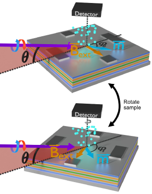
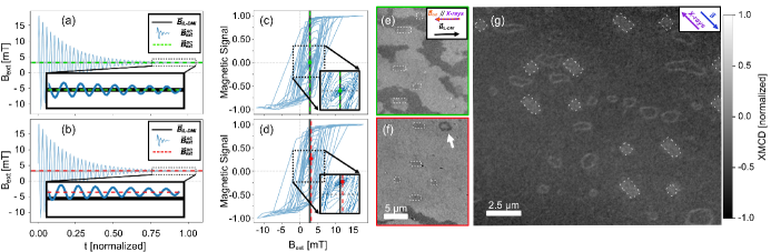
In order to obtain a magnetically non-trivial remanent state, a demagnetization protocol which consists of consecutively decreasing IP sinusoidal signals is applied. thus consists of an AC oscillating component (), and a DC or external field offset component (). The protocol is demonstrated in figure 2, where the magnetization is probed in a separate X-ray resonant magnetic scattering (XRMS) experiment, performed at SEXTANTS beamline in SOLEIL synchrotron. For this, XRMS hysteresis loops are taken where the specularly reflected signal is recorded, using field sequences where the IL-DMI exchange bias field () is either fully or partially compensated by . The X-ray beam spot used is 300 m in diameter Jaouen et al. (2004), and the X-ray beam was set to 13∘ of incidence with respect to the sample plane, giving large sensitivity to the IP magnetization Jal (2013).
Figures 2 (c,d) show the XRMS hysteresis loops for the two demagnetizing sequences in figures 2 (a,b). In the green (fully demagnetized case) shown in figure 2 (c), ’s component is fully compensated by , i.e., , with , yielding final zero net magnetic signal. This state corresponds to the one observed via XMCD-PEEM in figure 2 (e), where the area of black and white domains within the field of view (FOV) is indeed approximately equal. The situation is different for the red (partially demagnetized case) shown in figure 2 (d), where ’s component is not fully compensated (), reaching a final state with non-zero net magnetic signal. This agrees with the corresponding PEEM experiment shown in figure 2 (f), where there is a clear dominating magnetic configuration aligned with . In the partially demagnetized case, a number of ring-like magnetic textures (0.5-3.0 in diameter) is frequently observed by PEEM, for instance, the one marked by the white arrow in figure 2 (f). The emergence of a large number of rings is found in partially demagnetized states as the one in figure 2 (g), where an area with a larger field of view is shown. All the images shown here are taken at the Co edge and refer to states forming on the CoFeB layer, since the magnetic features are identical at both Fe and Co edges, with Co showing a significantly better signal-to-noise ratio due to the stoichiometry of the CoFeB layer (see supplementary material).
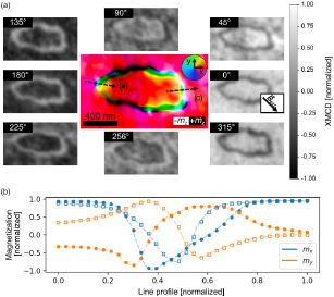
To understand better the magnetic configuration of these spin textures, vector imaging of one of the rings is performed by measuring several X-ray beam/sample projections. For this, the sample is rotated in the PEEM chamber with respect to the X-ray direction, as shown in figure 1. XMCD images are obtained for a total of 8 azimuthal angles, see figure 3 (a). The images have been previously rotated and aligned with respect to each other in order to have the same spatial orientation, following a similar procedure to the one described in Le Guyader et al. (2012). Additionally, deformations in different projection images are corrected by an algorithm which makes use of a combination of image registration techniques, using the marker’s geometrical shape as reference landmarks. These deformations arise from the fact that the used PEEM microscope does not inherently present circular symmetry. Some of the electron optical elements, in particular the 120∘ beam splitter, typically introduce image distortions which become relevant when overlaying images for different sample orientations.
The spatially resolved normalized magnetization vector () is then reconstructed Le Guyader et al. (2012); Ruiz-Gómez et al. (2018); Ghidini et al. (2022); Scholl et al. (2002); Chopdekar et al. (2013); Chmiel et al. (2018); Digernes et al. (2020), by performing a pixel-by-pixel least squares fitting of the XMCD profile (given by , with being the incident X-ray wave-vector) as a function of the azimuthal rotation angle. The resulting vector directions of are shown in the central image of figure 3 (a). The line profiles in figure 3 (b) evidence the presence of 360∘ DWs separating the outer and inner domains, whose orientation is the same, and the direction of within them is the result of the EA and directions. In the reconstruction, great precision is achieved in the determination of the IP components due to the grazing incidence of the X-rays, which on the other hand reduces the sensitivity to OOP components. Furthermore, the magnetic signal decreases in areas where the magnetization changes over small spatial lengthscales in comparison with the microscope’s resolution, giving a larger uncertainty in the domain walls’ OOP components.
360∘ DW rings have been previously observed in individual ferromagnetic Permalloy thin film layers Smith and Harte (1962), in multilayered heterostructures Heyderman et al. (1991); Heyderman, Chapman, and Parkin (1994); Portier and Petford-Long (2000), in exchanged biased films Schafer, Hubert, and Parkin (1993); Cho et al. (1999); Dean et al. (2011) and in magnetic tunnel junctions Gillies, Chapman, and Kools (1995). The role of Bloch lines Heyderman et al. (1991), DW splitting Heyderman, Chapman, and Parkin (1994) and dispersion in anisotropy Dean et al. (2011) have been proposed as mechanisms for explaining their formation.
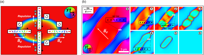
In order to determine the dependence between the stability of 360∘ DW rings and the IL-DMI effective field, focus is first set on their topology and magnetic charge distribution. For this, the simplified sketch of the vector reconstructed configuration shown in figure 4 (a) is used, assuming a fully IP texture. The figure shows an elongated, 360∘ DW ring with the EA along . A 1D 360∘ DW is a topologically non-trivial structure, having been sometimes denominated 1D skyrmions in the literature Cheng et al. (2019). However, when these DW form a ring structure as the one shown here, the net winding number computed along a line profile diametrically crossing the whole ring is zero due to the opposite chirality of the two encountered 360∘ DW. Therefore, a 360∘ DW ring as a whole is topologically trivial, which means that it can be continuously deformed into a single domain state.
Additionally, the elongation observed for the ring textures along the EA is expected based on magnetostatics arguments, i.e., Néel walls prefer to align parallel to the EA rather than perpendicular Hubert and Schäfer (2008) to it. Furthermore, the magnetic charge distribution along the ring structure is anisotropic, as evidenced by the "+" and "-" in the figure. For both (top and bottom) walls parallel to the EA, the two 180∘ DW forming the 360∘ DW repel each other, which in combination with the ferromagnetic exchange promote the growth of the annular domain (cyan). In the absence of a net magnetic field, this magnetic texture would expand and relax into broader domains separated by consecutive 180∘ DW Muratov and Osipov (2008). This contrasts with the (left and right) DW orthogonal to the anisotropy axis, where the demagnetizing field arising from the charge distribution now makes the two consecutive 180∘ DW attract each other, opposing the expansion of the annular domain promoted by ferromagnetic exchange. The competition of these interactions dictates the stability of the vertical 360∘ DW component at zero field Muratov and Osipov (2008). Thus, for the overall 360∘ DW ring texture to remain stable, a net non-zero field along the easy axis is required to compress from both inner and outer parts, preventing it from relaxing and expanding into broader domains, i.e., two consecutive domains separated by 180∘ DWs. Additionally, this field prevents the unwinding of the inner domain due to it being topologically trivial. This agrees well with previous observations of 360∘ DW rings in systems with exchange bias Schafer, Hubert, and Parkin (1993); Cho et al. (1999); Dean et al. (2011), since the field sequences used there do not add field offsets, resulting in net non-zero fields at remanence.
Finally, we focus on investigating the mechanism behind the nucleation of the rings using micromagnetic simulations. For this, solely a single IP thin film is modeled representing the CoFeB layer of the SAF, whose simulation parameters are summarized in table 1. As in experiments, is parallel to the EA (horizontal direction), and it is modeled through the effective field .
| Parameter | Value |
|---|---|
| Cells (x,y,z) | 3072 3072 1 |
| Cell size (x,y,z) | 4.5 4.5 5.0 [nm] |
| 0.02 | |
| 1.2 [A/m] | |
| 20 [pJ/m] | |
| [J/ | |
| Defect size | 0.8 [m] |
| Defect anisotropy | [J/ |
| Periodic boundary conditions | [repetitions] |
In order to model the formation process via micromagnetic simulations, the first step consists of obtaining a magnetic configuration formed by multiple domains, resembling an intermediate state during the demagnetizing protocol. For this, the simulation starts from a fully saturated configuration. Then, a field of increasing magnitude is applied along with a small component (5∘ with respect to ), which represents a misalignment between and the EA. A circular defect of 0.8 m radius and with 20 anisotropy value of the layer is included to trigger the nucleation of domains (cyan). Once reaches the switching field magnitude, the system is allowed to evolve dynamically, eventually reaching the state shown in [figure 4 (b), state (0)]. All 180∘ DWs in the simulation space have a component set by Jang et al. (2012), resulting in the magnetic charge distribution, once again represented by the "+" and "-" signs.
As DW of opposite charge get closer promoted by the growth of the inverted domain, the intensity of the demagnetizing field () associated to the magnetic charges begins to increase [figure 4 (b), state (1)]. The varying in combination with the constant , eventually reaches the sufficient field magnitude for overcoming the anisotropy dominated nucleation field, as a consequence locally inverting the magnetization. This allows for the formation of a new pair of 180∘ DWs during the reversal, with their core magnetization pointing along , given that the component of in this case is opposite and larger in magnitude than the original set by , i.e., > - . This is exemplified in the crop shown in [figure 4 (b), state (2)]; the new 180∘ DW forms next to the original from [figure 4 (b), state (1)], resulting in a 360∘ DW with configuration. Thus, for the formation of 360∘ DW and the forthcoming rings, it is key for the component of to be opposite in sign and greater in magnitude than . In the hypothetical case where either and/or were purely along , it would not have lead to the formation of the rings, as the existence of non-zero transverse field components are crucial.
From this point on, a ring is finally formed after the red domains shrink due to the opposing [figure 4 (b), states (3) - (5)]. The key role of an alternating field [figure 4 (b), states (0) - (1)] for the formation of 360∘ DW rings in a system with domains is similar to previous works in nanowires with injection pads Jang et al. (2012), where 360∘ DW were stabilized via the application of alternating external magnetic fields. Here, instead, the net magnetic field is dominated by or , for different steps of formation.
In this ideal simulation space, the ring eventually annhilates, in contrast with the experimental results where rings remain stable. This can be readily explained due to the presence of pinning sites, defects, and imperfections in the real sample that locally alter the magnetic energy landscape, leading to their meta-stability Coey (2010).
In conclusion, we have observed 360∘ DW rings via XMCD-PEEM magnetic vector reconstruction, forming in a SAF exhibiting exchange bias due to IL-DMI. These textures are observed at remanence after applying IP demagnetizing field sequences where a global offset in field is added. A combination of XMCD-PEEM and XRMS show how the rings are only found when the field offset does not perfectly compensate for the IL-DMI exchange bias field present in the SAF. We propose a mechanism for the formation and stability of the rings, based on analyzing their magnetic charge distribution and topology, in combination with micromagnetic simulations. First, a non-zero net IP field parallel to the easy axis, result of external and IL-DMI fields, is key for their stability at remanence. This net field in combination with pinning sites prevents their relaxation and annihilation due to their trivial topology. Secondly, a non-zero component of the net field perpendicular to the easy axis is required for their formation. This component sets the initial direction of two 180∘ walls at the start of the reversal process, which subsequently combine with two other 180∘ walls that form afterwards. The wall component of this second set of 180∘ walls is opposite to the original ones, set by the strong demagnetizing field in between domains that dominate as these become closer to each other. The combination of the two sets of consecutive 180∘ walls results in two 360∘ walls of opposite chirality, leading to a 360∘ wall ring. A deep understanding of the effect of IL-DMI on the magnetic reversal process and domain structure of SAFs is crucial for the potential exploitation of this effect in spintronic devices.
Acknowledgements.
This work was supported by UKRI through an EPSRC studentship, EP/N509668/1 and EP/R513222/1, the European Community under the Horizon 2020 Program, Contract No. 101001290 (3DNANOMAG), the MCIN with funding from European Union NextGenerationEU (PRTR-C17.I1), and the Aragon Government through the Project Q-MAD. The raw data supporting the findings of this study will be openly available at the DIGITAL.CSIC repository. A.H.-R. acknowledges the support by Spanish MICIN under grant PID2019-104604RB/AEI/10.13039/501100011033 and by Asturias FICYT under grant AYUD/2021/51185 with the support of FEDER funds. S.R-G. acknowledges the financial support of the Alexander von Humboldt foundation. L.S. acknowledges support from the EPSRC Cambridge NanoDTC EP/L015978/1. C.D. acknowledges funding from the Max Planck Society Lise Meitner Excellence Program. The ALBA Synchrotron is funded by the Ministry of Research and Innovation of Spain, by the Generalitat de Catalunya and by European FEDER funds. We acknowledge Synchrotron SOLEIL for providing the synchrotron radiation facilities (Proposal No. 20191674). S.M. acknowledges support from EPSRC project EP/T006811/1. M.A.N and M.F. acknowledge support from MICINN project ECLIPSE (PID2021-122980OB-C54).References
- Fernández-Pacheco et al. (2019) A. Fernández-Pacheco, E. Vedmedenko, F. Ummelen, R. Mansell, D. Petit, and R. P. Cowburn, “Symmetry-breaking interlayer dzyaloshinskii–moriya interactions in synthetic antiferromagnets,” Nature materials 18, 679–684 (2019).
- Han et al. (2019) D.-S. Han, K. Lee, J.-P. Hanke, Y. Mokrousov, K.-W. Kim, W. Yoo, Y. L. Van Hees, T.-W. Kim, R. Lavrijsen, C.-Y. You, et al., “Long-range chiral exchange interaction in synthetic antiferromagnets,” Nature materials 18, 703–708 (2019).
- Vedmedenko et al. (2019) E. Y. Vedmedenko, P. Riego, J. A. Arregi, and A. Berger, “Interlayer dzyaloshinskii-moriya interactions,” Physical review letters 122, 257202 (2019).
- Avci et al. (2021) C. O. Avci, C.-H. Lambert, G. Sala, and P. Gambardella, “Chiral coupling between magnetic layers with orthogonal magnetization,” Physical Review Letters 127, 167202 (2021).
- Huang et al. (2022) Y.-H. Huang, C.-C. Huang, W.-B. Liao, T.-Y. Chen, and C.-F. Pai, “Growth-dependent interlayer chiral exchange and field-free switching,” Physical Review Applied 18, 034046 (2022).
- Lau et al. (2016) Y.-C. Lau, D. Betto, K. Rode, J. Coey, and P. Stamenov, “Spin–orbit torque switching without an external field using interlayer exchange coupling,” Nature nanotechnology 11, 758–762 (2016).
- He et al. (2022) W. He, C. Wan, C. Zheng, Y. Wang, X. Wang, T. Ma, Y. Wang, C. Guo, X. Luo, M. Stebliy, et al., “Field-free spin-orbit torque switching enabled by interlayer dzyaloshinskii-moriya interaction,” arXiv preprint arXiv:2205.06706 (2022).
- Wang et al. (2022) Z. Wang, P. Li, Y. Yao, Y. L. Van Hees, C. F. Schippers, R. Lavrijsen, A. Fert, W. Zhao, and B. Koopmans, “Field-free spin orbit torque switching of synthetic antiferromagnet through interlayer dzyaloshinskii-moriya interaction,” arXiv preprint arXiv:2205.04740 (2022).
- Bekele et al. (2020) Z. A. Bekele, X. Lan, K. Meng, and X. Liu, “Enhanced field-free current-induced magnetization switching by interlayer exchange coupling with insulating spacer layer,” Journal of Applied Physics 127, 113902 (2020).
- Wang et al. (2021) K. Wang, L. Qian, S.-C. Ying, and G. Xiao, “Spin-orbit torque switching of chiral magnetization across a synthetic antiferromagnet,” Communications Physics 4, 1–7 (2021).
- Kammerbauer et al. (2022) F. Kammerbauer, W.-Y. Choi, F. Freimuth, K. Lee, R. Frömter, D.-S. Han, H. J. Swagten, Y. Mokrousov, and M. Kläui, “Controlling 3d spin textures by manipulating sign and amplitude of interlayer dmi with electrical current,” arXiv preprint arXiv:2209.01450 (2022).
- Jang et al. (2012) Y. Jang, S. R. Bowden, M. Mascaro, J. Unguris, and C. Ross, “Formation and structure of 360 and 540 degree domain walls in thin magnetic stripes,” Applied Physics Letters 100, 062407 (2012).
- Dean et al. (2011) J. Dean, A. Kohn, A. Kovacs, A. Zeltser, M. Carey, G. Hrkac, D. Allwood, and T. Schrefl, “The formation mechanism of 360 domain walls in exchange-biased polycrystalline ferromagnetic films,” Journal of Applied Physics 110, 073901 (2011).
- Aballe et al. (2015) L. Aballe, M. Foerster, E. Pellegrin, J. Nicolas, and S. Ferrer, “The alba spectroscopic leem-peem experimental station: layout and performance,” Journal of synchrotron radiation 22, 745–752 (2015).
- Stöhr and Siegmann (2006) J. Stöhr and H. C. Siegmann, “Magnetism,” Solid-State Sciences. Springer, Berlin, Heidelberg 5, 236 (2006).
- Beaurepaire et al. (2001) E. Beaurepaire, F. Scheurer, G. Krill, and J.-P. Kappler, Magnetism and synchrotron radiation, Vol. 34 (Springer, 2001).
- Yokoyama, Nakagawa, and Takagi (2008) T. Yokoyama, T. Nakagawa, and Y. Takagi, “Magnetic circular dichroism for surface and thin film magnetism: Measurement techniques and surface chemical applications,” International Reviews in Physical Chemistry 27, 449–505 (2008).
- Foerster et al. (2016) M. Foerster, J. Prat, V. Massana, N. Gonzalez, A. Fontsere, B. Molas, O. Matilla, E. Pellegrin, and L. Aballe, “Custom sample environments at the alba xpeem,” Ultramicroscopy 171, 63–69 (2016).
- Jaouen et al. (2004) N. Jaouen, J.-M. Tonnerre, G. Kapoujian, P. Taunier, J.-P. Roux, D. Raoux, and F. Sirotti, “An apparatus for temperature-dependent soft x-ray resonant magnetic scattering,” Journal of synchrotron radiation 11, 353–357 (2004).
- Jal (2013) E. Jal, Réflectivité magnétique résonante de rayons X mous: une sonde de la distribution d’aimantation complexe au sein de films minces, Ph.D. thesis, Grenoble (2013).
- Le Guyader et al. (2012) L. Le Guyader, A. Kleibert, A. F. Rodríguez, S. El Moussaoui, A. Balan, M. Buzzi, J. Raabe, and F. Nolting, “Studying nanomagnets and magnetic heterostructures with x-ray peem at the swiss light source,” Journal of Electron Spectroscopy and Related Phenomena 185, 371–380 (2012).
- Ruiz-Gómez et al. (2018) S. Ruiz-Gómez, L. Pérez, A. Mascaraque, A. Quesada, P. Prieto, I. Palacio, L. Martín-García, M. Foerster, L. Aballe, and J. de la Figuera, “Geometrically defined spin structures in ultrathin fe 3 o 4 with bulk like magnetic properties,” Nanoscale 10, 5566–5573 (2018).
- Ghidini et al. (2022) M. Ghidini, F. Maccherozzi, S. S. Dhesi, and N. D. Mathur, “Xpeem and mfm imaging of ferroic materials,” Advanced Electronic Materials 8, 2200162 (2022).
- Scholl et al. (2002) A. Scholl, H. Ohldag, F. Nolting, J. Stöhr, and H. A. Padmore, “X-ray photoemission electron microscopy, a tool for the investigation of complex magnetic structures,” Review of scientific instruments 73, 1362–1366 (2002).
- Chopdekar et al. (2013) R. Chopdekar, J. Heidler, C. Piamonteze, Y. Takamura, A. Scholl, S. Rusponi, H. Brune, L. Heyderman, and F. Nolting, “Strain-dependent magnetic configurations in manganite-titanate heterostructures probed with soft x-ray techniques,” The European Physical Journal B 86, 1–7 (2013).
- Chmiel et al. (2018) F. P. Chmiel, N. Waterfield Price, R. D. Johnson, A. D. Lamirand, J. Schad, G. van der Laan, D. T. Harris, J. Irwin, M. S. Rzchowski, C.-B. Eom, et al., “Observation of magnetic vortex pairs at room temperature in a planar -fe2o3/co heterostructure,” Nature Materials 17, 581–585 (2018).
- Digernes et al. (2020) E. Digernes, S. D. Slöetjes, A. Strømberg, A. D. Bang, F. K. Olsen, E. Arenholz, R. V. Chopdekar, J. K. Grepstad, and E. Folven, “Direct imaging of long-range ferromagnetic and antiferromagnetic order in a dipolar metamaterial,” Physical Review Research 2, 013222 (2020).
- Smith and Harte (1962) D. Smith and K. Harte, “Noncoherent switching in permalloy films,” Journal of Applied Physics 33, 1399–1413 (1962).
- Heyderman et al. (1991) L. Heyderman, H. Niedoba, H. Gupta, and I. Puchalska, “360° and 0° walls in multilayer permalloy films,” Journal of magnetism and magnetic materials 96, 125–136 (1991).
- Heyderman, Chapman, and Parkin (1994) L. Heyderman, J. Chapman, and S. Parkin, “Tem investigation of the magnetisation processes in exchange coupled multilayer films,” Journal of magnetism and magnetic materials 138, 344–354 (1994).
- Portier and Petford-Long (2000) X. Portier and A. Petford-Long, “The formation of 360 domain walls in magnetic tunnel junction elements,” Applied Physics Letters 76, 754–756 (2000).
- Schafer, Hubert, and Parkin (1993) R. Schafer, A. Hubert, and S. Parkin, “Domain and domain wall observations in sputtered exchange-biased wedges,” IEEE transactions on magnetics 29, 2738–2740 (1993).
- Cho et al. (1999) H. S. Cho, C. Hou, M. Sun, and H. Fujiwara, “Characteristics of 360-domain walls observed by magnetic force microscope in exchange-biased nife films,” Journal of applied physics 85, 5160–5162 (1999).
- Gillies, Chapman, and Kools (1995) M. Gillies, J. Chapman, and J. Kools, “Magnetization reversal mechanisms in nife/cu/nife/femn spin-valve structures,” Journal of applied physics 78, 5554–5562 (1995).
- Cheng et al. (2019) R. Cheng, M. Li, A. Sapkota, A. Rai, A. Pokhrel, T. Mewes, C. Mewes, D. Xiao, M. De Graef, and V. Sokalski, “Magnetic domain wall skyrmions,” Physical Review B 99, 184412 (2019).
- Hubert and Schäfer (2008) A. Hubert and R. Schäfer, Magnetic domains: the analysis of magnetic microstructures (Springer Science & Business Media, 2008).
- Muratov and Osipov (2008) C. Muratov and V. Osipov, “Theory of 360 domain walls in thin ferromagnetic films,” Journal of Applied Physics 104, 053908 (2008).
- Głowiński et al. (2017) H. Głowiński, A. Żywczak, J. Wrona, A. Krysztofik, I. Gościańska, T. Stobiecki, and J. Dubowik, “Cofeb/mgo/cofeb structures with orthogonal easy axes: perpendicular anisotropy and damping,” Journal of Physics: Condensed Matter 29, 485803 (2017).
- Devolder et al. (2016) T. Devolder, J.-V. Kim, L. Nistor, R. Sousa, B. Rodmacq, and B. Diény, “Exchange stiffness in ultrathin perpendicularly magnetized cofeb layers determined using the spectroscopy of electrically excited spin waves,” Journal of Applied Physics 120, 183902 (2016).
- Coey (2010) J. M. Coey, Magnetism and magnetic materials (Cambridge university press, 2010).