Trans-Inpainter: Wireless Channel Information- Guided Image Restoration via Multimodal Transformer
Abstract
Image inpainting is a critical computer vision task to restore missing or damaged image regions. In this paper, we propose Trans-Inpainter, a novel multimodal image inpainting method guided by Channel State Information (CSI) data. Leveraging the power of transformer architectures, Trans-Inpainter effectively extracts visual information from CSI time sequences, enabling high-quality and realistic image inpainting. To evaluate its performance, we compare Trans-Inpainter with RF-Inpainter, the state-of-the-art radio frequency (RF) signal-based image inpainting technique. Through comprehensive experiments, Trans-Inpainter consistently demonstrates superior performance in various scenarios. Additionally, we investigate the impact of CSI data variations on Trans-Inpainter’s imaging ability, analyzing individual sensor data, fused data from multiple sensors, and altered CSI matrix dimensions. These insights provide valuable references for future wireless sensing and computer vision studies.
Index Terms:
Image Inpainting, Deep Learning, Transformer, Channel State Information, Wireless Sensing, Multimodal1 Introduction
Image inpainting plays a crucial role in computer vision and finds applications in various domains such as medical imaging, surveillance, and remote sensing.
Traditional image inpainting methods, including exemplar-based synthesis and diffusion-based methods, struggle to address large-scale image deletions due to challenges in preserving image semantics [1], [2]. However, the rapid development of deep learning (DL) techniques has led to significant advancements in image processing, overcoming some limitations of traditional algorithms. DL-based image inpainting has emerged as a prominent research area in computer vision.
While DL-based image inpainting techniques have achieved remarkable progress in restoring missing or defective image parts, they still face challenges [1], [2], [3]. First, restored images often suffer from color distortion and lack realism compared to ground truth images, limiting their practical applications in monitoring, crime prevention, and path prediction. Second, existing DL inpainting techniques rely solely on visual information from the remaining pixels in the image to predict and fill damaged areas. As a result, their inpainting performance is severely constrained when the damaged region occupies a significant proportion of the image.
To address these challenges, leveraging radio frequency (RF) signals has emerged as a promising solution [4]. RF signals provide complementary information to visual data and can assist in estimating the spatial distribution of obstacles or environmental changes. By integrating RF signals with residual visual information, the accuracy and realism of image inpainting can be improved. In our previous work [5], we developed a multimodal image inpainting method named RF-Inpainter. RF-Inpainter utilizes received signal strength indicator (RSSI) as auxiliary information to infer damaged image areas. It simultaneously takes RSSI sequences and corresponding defective image sequences (or videos) as inputs to a deep U-Net architecture, achieving more satisfactory inpainted images than single-modal baselines (Image-only inpainting and RSSI-only imaging).
The U-Net architecture of RF-Inpainter is structured as a combination of convolutional neural networks (CNNs) and multilayer perceptrons (MLPs) dedicated to processing images and RSSI signals, respectively. While RF-Inpainter is a powerful neural network, the transformer architecture, particularly its multi-head attention mechanism, has demonstrated superior effectiveness in handling multimodal time-sequence information [6], [7]:
-
•
Benefit 1: Modality-Agnostic Architecture for Multi-Modal Data Processing
As opposed to CNN’s convolutional layers imposing image-specific inductive bias (focusing on neighboring pixel correlations that are valid for images) into the model, the modality-agnostic architecture of transformers, combined with their self-attention mechanisms and multi-head attention capabilities, enables seamless processing and integration of diverse modalities. For example, Meta’s ImageBind processes text, audio, visual movement, thermal, and depth data using only the Transformer architecture [8]. This versatility is particularly advantageous for multimodal image inpainting tasks that require integrating visual and temporal information in images and RF signals.
In contrast, specialized architectures such as convolutional or recurrent layers are limited to specific modalities, necessitating complex modifications to handle multimodal data effectively. Notably, certain properties used in visual transformers have also been adopted to enhance CNNs, such as patchification, which divides an input image into groups of pixels, reducing complexity [9].
-
•
Benefit 2: Identifying Long-Term Dependencies
In RF-based image inpainting, the transformer’s ability to capture long-range dependencies and model temporal relationships is crucial. Transformers utilize a self-attention mechanism with a large reception field that captures the correlations over the entire range, enabling them to extract temporal information from RF signal time series and generate accurate and visually appealing inpainted images.
Meanwhile, the capacity to handle long-term dependencies among pixels allows transformers to capture global context information essential for image inpainting. Additionally, attention mechanisms facilitate selective updating of specific areas in an image, preserving existing structures and details while filling in missing information. In contrast, RF-Inpainter’s convolutional layer has a limited reception field, making it challenging to identify correlations between distant pixels and lacking selective updating capability, which may lead to overwriting important features in inpainted regions.
While Transformer plays a significant role in RF-based multimodal image inpainting, it is essential to acknowledge that the model architecture may not be the sole factor limiting the inpainting performance. RSSI, the wireless data used in RF-Inpainter, is prone to issues such as multipath fading and temporal dynamics, which result in sensitivity to environmental changes and reduced accuracy in inpainting. On the other hand, CSI, a physical layer power feature that characterizes the wireless channel conditions between access points and devices, offers distinct advantages over RSSI [10], [11].
In recent years, CSI has gained significant attention due to its wide range of applications in wireless sensing tasks, including device-free localization, motion tracking, and activity recognition. Pioneering work in this area has demonstrated centimeter-level accuracy. Unlike RSSI, which provides a single value per packet, CSI is measured per orthogonal frequency-division multiplexing (OFDM) from each packet. This characteristic makes CSI more robust in complex environments and enables it to provide richer information about the wireless channel. Furthermore, CSI encompasses additional parameters such as phase and amplitude information, contributing to a more comprehensive representation of the wireless channel and potentially containing more precise visual information.
In this work, we propose Trans-Inpainter, a novel CSI-guided multimodal image inpainting method built on transformer architectures. By mapping CSI time sequences to corresponding defective image sequences and feeding them into the transformer model, Trans-Inpainter achieves state-of-the-art performance in restoring missing parts while maintaining color and texture consistency, even when over of the image area is damaged.
Compared to RF-Inpainter, Trans-Inpainter’s novelty is two-fold:
-
•
Transformer architecture for multimodal processing and long-term dependency purposes.
-
•
The use of CSI for reflecting high-fidelity signals and environmental characteristics compared to coarse RSSI data.
The main contributions of our work are summarized as follows:
-
•
We propose Trans-Inpainter, a novel CSI-guided multimodal image restoration method, to generate high-quality, realistic reconstructed images. To the best of our knowledge, this is the first work that explores the extraction of visual information from CSI time sequences using transformer architectures.
-
•
We compare the performance of Trans-Inpainter with RF-Inpainter, a state-of-the-art multimodal RF-based image inpainting technique, under more complex and challenging experimental scenarios. We also compare special cases of Trans-Inpainter and RF-Inpainter, i.e., single-modality image inpainting when only RF or image data is available, respectively. The results demonstrate that multimodal Trans-Inpainter consistently outperforms other approaches in all cases.
-
•
To further improve the performance of Trans-Inpainter, we investigate the impact of CSI data variation on its imaging ability. Specifically, we experimentally analyze how using CSI data from individual sensors at different locations, fusing CSI from multiple sensors at different locations, and changing the temporal or frequency dimensions of the CSI matrix affect the CSI-based imaging results, respectively. The conclusions drawn from these results provide essential references and insights for future wireless sensing studies, such as Wi-Fi-based imaging, motion recognition, and localization.
The remainder of this paper is organized as follows: Section 2 reviews related work on DL-based image inpainting and multimodal image inpainting. Section 3 provides a detailed description of Trans-Inpainter, including the system model, CSI preprocessing, model architecture, and training & prediction procedures. In Section 4, we present the experimental results and compare the performances of Trans-Inpainter with RF-Inpainter and other single-modal inpainting baselines. The impact of CSI data changes on imaging performance is demonstrated in Section 5. Finally, we conclude the paper and discuss future directions in Section 6.
2 Related Work
2.1 Deep Learning-based Image Inpainting
Deep learning has made significant progress in inpainting tasks. Compared to traditional algorithms, DL-based approaches have demonstrated improved effectiveness in capturing high-level semantics and producing superior results [1], [2], [3], [12].
CNNs and generative adversarial networks (GAN) are the two most important neural networks in the study of deep learning (DL)-based inpainting methods, as indicated by several research contributions [2], [3], [12]. GAN and CNN-based image inpainting methods have attracted much attention since the Context Encoder proposal by Pathak et al. [13]. Many researchers have proposed novel techniques to enhance the effectiveness of these methods. For example, some have introduced semantic attention layers to the GAN-based inpainting method, as proposed by Jiahui Yu [14]. Other researchers have proposed partial convolution to adapt the convolutional parameters to account for image breakage [15], [16].
As the recovery of complex patterns directly can be challenging for the model, some researchers have incorporated additional information such as edges and semantics to aid in image completion [17], [18]. To address the issue of empty information in corrupted areas, some researchers have adopted the ”two-stage” encoder-decoder network architecture, where the encoder outputs an intermediate image as a guide for the inpainting process, and the decoder completes the image based on this intermediate image [19], [20]. In addition, some researchers have proposed a parallel framework that utilizes extra information such as complementary images and image edges [21], [22]. The parallel framework offers a clear advantage over the ”two-stage” strategy since it is usually faster in the inference phase since corrupted images only need to pass through one network.
In recent years, transformer networks, a type of attention-based architecture, have demonstrated impressive results in natural language processing and high-level vision applications. Attention operators within transformers excel in long-range modeling and dynamic weighting, which allows the model to borrow feature patches from distant uncorrupted patches to generate new patches for the corrupted regions, making them more suitable for image inpainting than CNNs and GANs. Several studies, including [23], [24], and [25], have explored how contextual attention operators search the entire image to fill the missing regions. Ye Deng et al. proposed the contextual transformer network, which models the affinity between uncorrupted and corrupted image regions and focuses on constructing affinity inside both uncorrupted and corrupted regions, resulting in better contextual information capture across multiple scales and more reliable inpainting [6]. Additionally, Wenbo Li et al. introduced the Mask-Aware Transformer, a large-hole inpainting method that combines the strengths of transformers and convolutions by customizing an inpainting-oriented transformer block where the attention module aggregates non-local information only from partial valid tokens, indicated by a dynamic mask [26]. Overall, transformer networks’ ability to handle long-range dependencies and variable-length sequences, coupled with their superior performance and efficiency, make them an ideal choice for image inpainting tasks.
Regardless of the deep learning models used, current state-of-the-art inpainting techniques are limited in producing visually realistic and semantically reasonable images, as they rely solely on residual information in the image to infer missing content, resulting in issues such as color discrepancies, blurriness in reconstructed images, and differences between the reconstructed and ground truth images [3], [12]. Such shortcomings are unacceptable for practical applications like criminal investigations and traffic cameras.
2.2 Multimodal Image Inpainting
The state-of-the-art studies on multimodal image inpainting mainly focus on restoring images from textual information.
The field of vision-language research has grown rapidly, and one of the exciting emerging topics is language-guided image inpainting. This class of systems combines natural language instructions with given pixels to perform image inpainting and has great potential for applications in computer vision and natural language processing. Recently, autoregressive model-based multimodal pre-training has shown promising results in visual synthesis capabilities, as evidenced by the success of systems like DALL-E [27], CogView [28], and Imagen [29]. This has opened up possibilities for using generative pre-training mechanisms for language-guided image inpainting. Various studies have explored the fusion of multimodal features to introduce text description into the image inpainting task. These include MMFL developed by Qing Lin et al. [30], TDANet proposed by Lisai Zhang et al. [31], and TGNet by Ying Gao et al. [31]. More recently, Minheng Ni et al. proposed NÜWA-LIP, a language-guided inpainting approach that incorporates defect-free VQGAN (DF-VQGAN) with multi-perspective sequence to sequence (MP-S2S) [32]. DF-VQGAN introduces relative estimation to control receptive spreading and adopts symmetrical connections to protect information. At the same time, MP-S2S enhances visual information from complementary perspectives, including both low-level pixels and high-level tokens. Ailin Li et al. proposed MIGT, a multimodal image inpainting framework that also uses natural language as a modality of hints to fill the missing region while maintaining coherence with the source region and semantic consistency with the textual description [33].
However, language or text loses a lot of information compared to images, and even if an image is described in detail, the amount of information and precision contained in text is still very limited compared to images. In addition, language is a highly subjective and abstract form of expression. Since the subject of the description is different, there are inevitable deviations between the content of the description and the actual situation so that the same text can correspond to an infinite number of possible images. Therefore, even if the semantic interpretation is precise, achieving a completely distortion-free restoration is impossible compared to the original image.
Fortunately, the development of wireless sensing technology in recent years has offered a solution to this problem [34], [35]. Wireless data such as CSI and RSSI provide more visual information for image inpainting because they directly capture the physical characteristics of the environment in which the image was captured. CSI and RSSI data can reveal information about the geometry, material, and electromagnetic properties of objects in the environment and their relative positions and distances from the device that captured the wireless data. Our previous works, [4] and [5], pioneered the idea that RSSI can be used to better infer the missing content in an image, especially in cases where the missing content is related to the physical characteristics of the environment, such as objects and their positions. Expanding on prior research, we present a novel technique for generating higher-quality, more realistic reconstructed images using CSI and transformers in image inpainting. This work is the first instance of employing transformers to extract visual information from the CSI of WiFi signals for inpainting tasks.
3 Trans-Inpainter: CSI-Guided Image Restoration via Multimodal Transformer
3.1 System Model
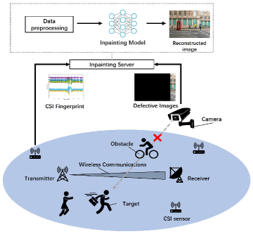
The system model of Trans-Inpainter, as depicted in Fig. 1, synergistically incorporates information from cameras and CSI sensors to enhance the accuracy and robustness of image inpainting. This comprehensive framework comprises four pivotal components: cameras, CSI sensors, a data processing module, and a deep neural network model specifically designed for image inpainting.
Cameras and CSI sensors collect imagery and CSI data from the same environment. While cameras capture RGB images, CSI sensors capture wireless communication channel characteristics. Due to obstacles such as humans or objects, the captured images might exhibit missing portions. In such cases, CSI sensors play a crucial role in providing supplementary environmental information to facilitate the inference of the missing image regions, known as CSI-guided image inpainting.
The data processing module assumes responsibility for preprocessing both the image and CSI data. This module undertakes various operations, including synchronization, filtering, feature extraction, and principal component analysis (PCA), on both types of data.
The deep neural network model for image inpainting adopts a transformer architecture renowned for capturing long-range dependencies in sequential data. Leveraging this multimodal transformer, the model ingests defective image sequences (specifically video data) alongside corresponding CSI sequences as inputs. Subsequently, it generates output image sequences that closely approximate the ground truth, eliminating any missing regions.
3.2 Data Collection and Preprocessing
3.2.1 Data Collection
In order to measure Channel State Information (CSI), the WiFi transmitter employs Long Training Symbols (LTS) within the packet preamble. In the context of Multiple-Input, Multiple-Output Orthogonal Frequency Division Multiplexing (MIMO-OFDM) WiFi channels, the available frequency spectrum is divided into multiple subcarriers, enabling efficient communication. Each subcarrier is associated with predetermined symbols contained within the LTS. By utilizing the original LTS and the received signals, the WiFi receiver estimates the CSI matrix. The estimation process models the WiFi channel for each subcarrier through the equation , where y denotes the received signal, x represents the transmitted signal, captures the CSI data, and n corresponds to the noise vector.
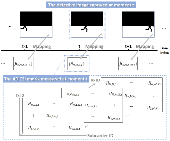
The estimated CSI data manifests as a complex-valued 3D matrix, characterizing variations in the MIMO channel across spatial, frequency, and temporal domains. In a MIMO-OFDM channel featuring transmit antennas, receive antennas, and subcarriers, the CSI matrix portrays the amplitude attenuation and phase shift of multipath channels. This matrix can be likened to a digital image with spatial resolution of and color channels [36]. To incorporate temporal information, the matrix expands to 4 dimensions, denoted as . We refer to this 4D matrix as the CSI matrix.
Within the context of image inpainting, the amplitude of CSI proves valuable in providing additional insights into the wireless channel between the transmitter and receiver. It offers information concerning signal strength across various spatial and temporal modes.
Conversely, we exclude the phase component of CSI due to its diminished significance in image inpainting tasks, unlike other signal processing applications such as phase estimation or beamforming. Furthermore, the phase of CSI is susceptible to noise and measurement errors, making accurate estimation challenging in practical scenarios. By disregarding the phase, we streamline the inpainting process, focusing solely on utilizing the amplitude of CSI to guide the reconstruction. As a result, the CSI matrix required for collection becomes a real-valued 4D matrix: .
To ensure the synchronization and simultaneous acquisition of image frames and corresponding matrices in the CSI sequences, we perform clock synchronization and unify the sampling rates of both cameras and CSI sensors at a rate of before data collection. This precautionary measure minimizes temporal discrepancies that could lead to inaccurate inpainting outcomes.
3.2.2 Data Preprocessing
Images are captured concurrently from multiple fixed-position cameras at the same time intervals as the collection of CSI matrices. These collected images undergo preprocessing to eliminate artifacts and noise, as well as resizing to a standardized square dimension (e.g., pixels).
While synchronization efforts are implemented prior to data collection, ensuring that each CSI matrix corresponds precisely to an image captured at the exact moment remains challenging. Consequently, after obtaining both types of data, an additional step of isochronization is performed to facilitate their integration into deep learning frameworks. The isochronization process follows the subsequent procedures:
-
•
Specify the time of the experiment.
-
•
Establish a reference time by dividing the experiment time into 0.1-second intervals.
-
•
Utilize bisection search to locate the data acquisition time point that is closest to the reference time.
Ultimately, the images and CSI matrices become isochronized, allowing their utilization without explicit time information. The achievement of temporal isochronization between the CSI matrices and their corresponding images signifies the completion of the mapping between the CSI matrix and the image. This mapping result is visually illustrated in Fig. 2.
Furthermore, it is essential to address the potential impact of noise or interference on CSI, as such factors can introduce inaccuracies in the image inpainting process. To mitigate these effects, a cleaning process is performed by applying a low-pass filter to the CSI amplitude component. Then, pilot and null subcarriers are removed to enhance the quality of the CSI matrices.
3.3 Trans-Inpainter Model Architecture
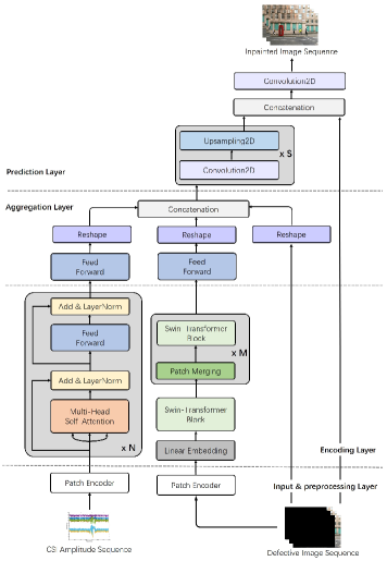
The Trans-Inpainter model, illustrated in Fig. 3, encompasses four key components: the Input & Preprocessing Layer, Encoding Layer, Aggregation Layer, and Prediction Layer.
3.3.1 Input & Preprocessing Layer
We begin by processing the image sequence and CSI amplitude sequences obtained from multiple CSI devices. These sequences are fed through dedicated input layers for further processing.
To effectively handle image sequences, a patch encoder is employed to facilitate subsequent processing in the transformer model. The patch encoder plays a pivotal role in segmenting each image into smaller, more manageable patches. By doing so, it transforms the image into a sequence of fixed-length vectors, known as patch embeddings, while preserving positional information through associated encodings.
Conversely, the CSI matrix sequences acquired from each sensor undergo a fusion process to consolidate them into a unified representation. This fusion is accomplished through concatenation, enabling subsequent processing as a cohesive unit. Similar to the image sequence, a patch encoder is applied to the fused CSI representation. However, in this case, the patch encoder does not include the embedding and positioning components.
Unlike images, CSI data does not possess the same spatial structure or inherent spatial relationships between patches. The CSI matrix represents the amplitude attenuation of multipath channels, and its elements do not correspond to localized image content. Therefore, the embedding step, which aims to capture local image features, is not applicable or meaningful for CSI data. Similarly, the positioning components, which capture the spatial relationships between patches in images, do not have direct relevance to the CSI matrix. The CSI matrix does not possess spatial coordinates or relationships in the same manner as images. Instead, it represents channel variations across spatial, frequency, and time domains. Since the embedding and positioning components are designed to handle the spatial aspects of images, they are unnecessary and do not contribute meaningful information when applied to the CSI data. Hence, the patch encoder for CSI data omits these components, focusing solely on segmenting the CSI matrix into manageable patches.
By employing the patch encoder for both the image sequence and fused CSI representation, we facilitate subsequent stages of the transformer model, leveraging the benefits of patch-wise processing for the images while preserving the integrity of the CSI data.
3.3.2 Encoding Layer
The Encoding Layer of the Trans-Inpainter model comprises two essential components: the CSI encoder and the image encoder.
The CSI encoder is designed to extract visual information from CSI matrices, drawing inspiration from the conventional transformers proposed in the seminal works of Vaswani et al. [37] and Dosovitskiy et al. [38]. This encoder consists of multiple layers, each featuring a multi-head self-attention sub-layer and a feed-forward sub-layer.
The self-attention sub-layer allows the network to focus selectively on the most salient input components, capturing relevant dependencies within the CSI data. Meanwhile, the feed-forward sub-layer applies non-linear transformations to the input, facilitating more complex and expressive representations.
In parallel, the image encoder is constructed based on the Swin Transformer, a versatile computer vision backbone initially introduced by Liu et al. [39]. The Swin Transformer employs a hierarchical architecture and utilizes shifted windows for computation. This windowing scheme enhances efficiency by limiting the self-attention computation to non-overlapping local windows while enabling cross-window connections. Notably, the Swin Transformer has exhibited exceptional performance in COCO object detection and ADE20K semantic segmentation tasks, outperforming previous models by a significant margin. Its adaptability and versatility make it suitable for a wide range of image-based tasks, including image inpainting, as demonstrated in the work of Liang et al. [40].
To prepare the image encoder, we performed pretraining on a large-scale dataset, ImageNet-22k, consisting of 22,000 object categories with 14 million images. Pretraining on this comprehensive dataset allows the model to learn meaningful and transferable features that can benefit various computer vision tasks. Subsequently, the model was fine-tuned on a smaller-scale dataset, ImageNet-1k, which contains 1,000 object categories and 1.2 million images. Fine-tuning on a dataset specifically tailored to the image inpainting task enables the model to adapt and refine its performance by capturing task-specific characteristics and nuances.
3.3.3 Aggregation Layer
The Aggregation Layer plays a crucial role in merging the outputs from the image encoder and the CSI encoder to form a comprehensive representation for the inpainting process.
Starting with the outputs of the image encoder and the CSI encoder, a feed-forward network is employed to reduce the dimensionality of the concatenated feature maps effectively. This reduction aids in streamlining the subsequent operations and optimizing computational efficiency.
The resulting outputs from the feed-forward network are then concatenated with the reshaped input defective image sequence. This concatenation process ensures the integration of the visual information extracted by the image encoder and the contextual information derived from the CSI encoder. Combining these representations, the Aggregation Layer establishes a holistic view of the input data, enabling a comprehensive understanding of the missing regions in the image sequence.
3.3.4 Prediction Layer
The Prediction Layer is responsible for generating an image sequence that corresponds to the input image sequence with the missing parts effectively filled in. This layer employs a series of 2D convolutional and 2D upsampling layers to achieve this task.
To enhance the model’s performance, skip connections are introduced between the input and output layers. These skip connections enable the model to leverage information from the input images and propagate it to the output images. By doing so, the model can preserve the content of the input images and generate more realistic and visually coherent output images.
Including skip connections helps address the challenge of maintaining consistency and coherence throughout the inpainting process. By allowing information to flow directly from the input layers to the output layers, the model can effectively utilize low-level details and high-level context from the original image sequence. This not only aids in preserving the overall structure and content of the input images but also contributes to generating more visually appealing and plausible output images.
3.4 Training and Prediction Procedures
Trans-Inpainter undergoes a comprehensive training and prediction process to effectively inpaint missing regions in image sequences.
During the training phase, the model is trained on a large dataset comprising paired image sequences and their corresponding CSI matrices, where the ground truth images are known. The model learns to map the defective images and CSI matrices to their respective ground truth images by minimizing a loss function. This training process enables the model to capture the intricate relationships between the visual information in the images and the contextual information provided by the CSI matrices. Following training, the model is evaluated on a separate validation dataset to assess its performance and inpainting capabilities.
Once the model is trained and validated, it can be deployed for prediction tasks whenever new CSI matrices and RGB images are obtained in real-time. Using the temporal series of CSI matrices and defective images acquired in real-time, the Trans-Inpainter model predicts the missing image parts. Leveraging the learned knowledge and patterns from the training phase, the model effectively utilizes the dynamic information in the CSI matrices and the visual information from the defective images to produce inpainted results in real-time.
4 Performance Evaluation
4.1 Setup
This section provides a detailed description of the experimental setup used to evaluate the performance of Trans-Inpainter in a wireless communication scenario.
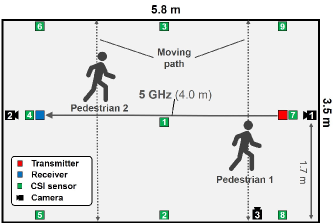
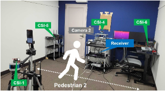
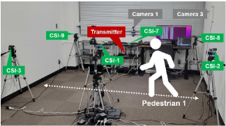
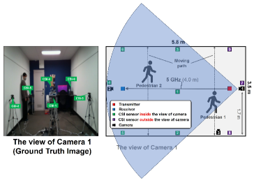
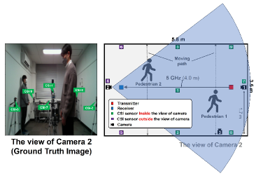
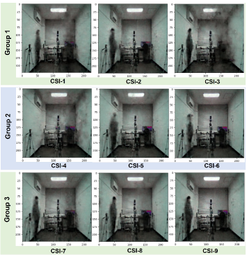
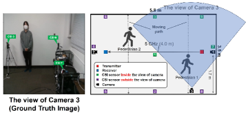
The experiment was conducted indoors, where the line-of-sight path of a 5 GHz band IEEE 802.11ac wireless LAN connection was periodically obstructed by two pedestrians. The equipment used in the experiment and the routes taken by the pedestrians are depicted in Fig. 4. Snapshots of the experimental environment are shown in Fig. 5. To generate traffic, wireless LAN devices were installed at both ends of the room, and iperf was used as the traffic generator [41]. To capture the wireless LAN signal and obtain CSI, nine CSI sensors were strategically placed in the experimental environment. These sensors were also responsible for collecting RSSI data, facilitating the comparison between CSI and RSSI for image inpainting. The movement of pedestrians caused variations in the radio propagation environment, leading to changes in both CSI and RSSI values. The experimental environment, including the pedestrians’ movements, was captured by three RGB cameras. The equipment used in the experiment is listed in Table I. The CSI data was acquired using custom firmware, Nexmon CSI, on a Raspberry Pi. It is important to note that the Raspberry Pi with Nexmon CSI was not used for wireless communication but instead obtained CSI information by sniffing the signals from the receiver in monitor mode. For ease of reference, each CSI sensor is labeled as CSI- according to its ID number as shown in Fig. 4.
The experiment was conducted over 30 minutes. Data collection and preprocessing were performed following the method described in Section 3.2. This resulted in temporally continuous sequences of RGB images captured from three different angles, nine corresponding sequences of CSI matrices from different sensors, and nine sequences of RSSI values. Each image sequence consisted of 18,000 RGB images with dimensions , each CSI sequence contained 18,000 matrices, and each RSSI sequence comprised 18,000 consecutive RSSI values.
|
|
| Receiver | NETGEAR Nighthawk X10 |
|---|---|
| Transmitter | NETGEAR Nighthawk X10 |
| Wireless LAN standard | IEEE 802.11ac |
| Channel | 36 |
| Bandwidth | 80 MHz |
| CSI sensor | Raspberry Pi 4 model B |
| CSI sensor firmware | Nexmon CSI [42] |
| CSI measurement rate | 500 Hz |
| Camera 1,2 | RealSense L515 |
| Camera 3 | RealSense D435 |
4.2 Baselines & Metrics
RF-Inpainter, a state-of-the-art RF-based multimodal inpainting approach, serves as the primary baseline for comparison in this study.
Initially, we conduct a comprehensive comparative analysis of the multimodal inpainting capabilities demonstrated by both Trans-Inpainter and RF-Inpainter. Additionally, we investigate specific scenarios where only data from a single modality (either image or RF signal) is available for both Trans-Inpainter and RF-Inpainter. Furthermore, we emphasize the substantial amount of visual information embedded in the CSI matrix in contrast to the RSSI value sequence by evaluating the resulting images obtained using each modality.
To ensure an objective evaluation of the inpainting performance of the respective methods, we utilize two widely adopted metrics for assessing image quality: the mean peak signal-to-noise ratio (PSNR) and the mean structural similarity index (SSIM). These metrics facilitate a quantitative measurement of the inpainting quality by calculating the PSNR and SSIM values for all the inpainted test images.
4.3 Trans-Inpainter vs. RF-Inpainter
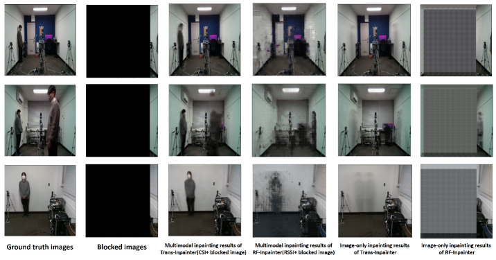
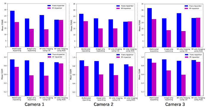
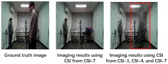
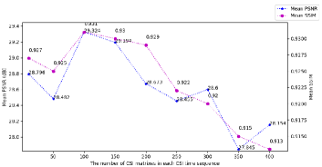
We present a comprehensive analysis of the visual results obtained from the multimodal inpainting, RF-only imaging, and image-only inpainting methods, as displayed in Fig. 6 and Fig. 7. These visual results are accompanied by the corresponding objective evaluation results summarized in Fig. 8.
4.3.1 Multimodal Image Inpainting
In multimodal inpainting, the utilization of both defective images and RF data is necessary. However, in this experiment, we did not consider multiple occlusion scenarios (random, vertical, and horizontal blocking) for image inpainting, as we have focused on the challenging task of heavily occluded images where more than of the content is missing. Successful inpainting under such severe occlusions indicates the method’s applicability to other scenarios as well, as demonstrated in our previous work [5].
For maximizing the performance of multimodal RF-Inpainter, we utilize RSSI as the wireless information, while CSI is employed to optimize the multimodal inpainting ability of Trans-Inpainter. The results presented in Fig. 8 and Fig. 7 demonstrate that Trans-Inpainter outperforms RF-Inpainter in utilizing CSI data, whereas RF-Inpainter performs better with RSSI data. Furthermore, we highlight the superiority of CSI over RSSI in RF-imaging and multimodal inpainting by using either RSSI from nine sensors or CSI data from four sensors. This choice is based on our previous work [5], which showed that an increase in the amount of RF data used could further enhance RF-imaging quality.
To ensure that the RF data and images used for multimodal inpainting correspond to the same local environment, we select the RF data obtained from the CSI sensors along the camera’s view. For example, when using the dataset of images captured by Camera 3, the CSI data utilized should be collected from CSI-1, CSI-3, CSI-7, and CSI-9.
The results presented in Fig. 8 and Fig. 6 not only demonstrate the superior performance of Trans-Inpainter compared to RF-Inpainter (with a maximum PSNR gap of and an SSIM improvement of ) but also highlight the advantage of using both types of data simultaneously for achieving better image inpainting results compared to using data from a single modality alone.
4.3.2 RF-only Imaging
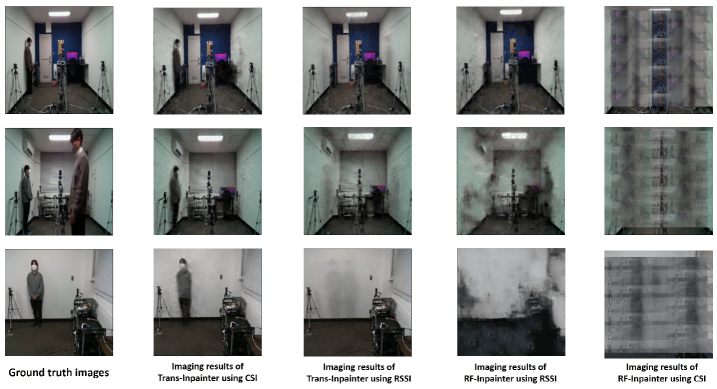
We conducted various experiments using different combinations of models and RF data to determine the optimal solution for RF-based imaging. Specifically, we evaluated the imaging abilities of Trans-Inpainter and RF-Inpainter using both CSI and RSSI datasets.
The experimental results presented in Fig. 8 demonstrate that feeding the CSI matrix sequence into Trans-Inpainter yields the clearest and most complete images, as evidenced by the highest Mean PSNR and SSIM scores in Fig. 7. Notably, Trans-Inpainter achieves these results without relying on any visual information. Conversely, RF-Inpainter performs poorly when reconstructing images from CSI. Furthermore, the performance of both Trans-Inpainter and RF-Inpainter significantly deteriorates when using RSSI data. However, as indicated by the Mean PSNR and SSIM scores in Fig. 8, Trans-Inpainter is slightly more effective than RF-Inpainter in extracting visual information from RSSI. Thus, we can conclude that CSI contains much richer visual information than RSSI, but extracting this information relies on the attention mechanism implemented in Trans-Inpainter.
It is worth noting that RF-Inpainter did not achieve the same level of effectiveness as reported in [5] in this experiment. This discrepancy may be attributed to the absence of pedestrians holding up a whiteboard, which was done in the previous work to increase the reflective area of RF signals. As a result, the fluctuations in RSSI and CSI values were less pronounced, making the imaging task more challenging in our study. Additionally, this work imposes higher demands on image resolution, as the size of the images to be reconstructed is enlarged from to , further increasing the difficulty of the imaging task.
4.3.3 Image-only Inpainting
The results depicted in Fig. 6 and Fig. 8 demonstrate a significant performance advantage of Trans-Inpainter over RF-Inpainter, even when using only limited residual image information. Trans-Inpainter successfully repairs all the damaged image areas, whereas RF-Inpainter exhibits large unrepaired regions in its inpainted results. However, it is important to note that the reconstructed portraits produced by Trans-Inpainter do not match the clarity of the ground truth images, resulting in comparatively inferior performance in image-only inpainting compared to multimodal inpainting. Furthermore, Fig. 8 indicates that CSI-only imaging with Trans-Inpainter consistently outperforms image-only inpainting, further emphasizing the effectiveness of our proposed method.
5 Impact of CSI Changes on Imaging Performance
The utilization of CSI is essential in image inpainting using Trans-Inpainter. As the experiment progresses, we have observed that variations in CSI data have diverse effects on the imaging results. In this section, we conduct additional experiments and analyze the outcomes by using CSI data from different sensors at various locations, combining CSI from multiple sensors, and exploring how changes in the time or frequency dimension of the CSI matrix affect the imaging results.
5.1 Imaging with CSI from Individual Sensors at Different Locations
|
|
|
|
|
|
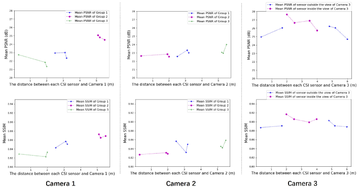
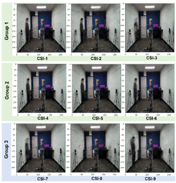
To investigate the impact of the location of CSI sensors on the imaging results, we conducted imaging experiments using CSI data from each sensor to reconstruct images from the viewpoints of Camera 1, Camera 2, and Camera 3, respectively.
Based on the distance to Camera 1 and Camera 2, we divided the CSI sensors into three groups: Group 1 (CSI-1, CSI-2, CSI-3), Group 2 (CSI-4, CSI-5, CSI-6), and Group 3 (CSI-7, CSI-8, CSI-9). As shown in Fig. 9 and Fig. 10, Group 1 and Group 2 sensors are within the field of view of Camera 1, while Group 3 is located outside its view. For Camera 2, only Group 2 sensors are excluded from its view.
5.1.1 Camera 1
The results of the Camera 1 dataset are shown in Fig. 9 and Fig. 12. Overall, we obtained better imaging results, both visually and objectively, by using CSI from sensors inside the view of Camera 1 rather than outside. Groups 1 and 2 show significantly better imaging quality than Group 3, as evidenced by higher mean PSNR and SSIM scores. Additionally, as the distance between the CSI sensor and the camera increases (from to ), the imaging results improve. The mean PSNR and SSIM scores of Group 2 reach their peak ( in PSNR and in SSIM), corresponding to the clearest images in Fig. 9. Group 1 results in a slight degradation of imaging quality compared to Group 2 (approximately in PSNR and in SSIM). Conversely, Group 3 exhibits the lowest scores ( in PSNR and in SSIM) in Fig. 12, corresponding to the worst imaging quality in Fig. 9.
The rationale behind these observations is that the CSI data collected within the camera’s field of view more adequately captures the spatial, physical information within that localized environment, enhancing the imaging quality. Moreover, appropriately increasing the distance between the CSI sensor and the camera within a certain range allows the sensor to collect more Wi-Fi signals reflected back from different angles within the room, providing a more comprehensive perception of the environment.
However, it is important to note that the distance between the CSI sensor and the camera should not be too far, even if the sensor is located within the camera’s field of view, as the intensity of radio signals along the propagation path may vary. Longer propagation paths introduce more noise and interference into the wireless data, leading to significant degradation of imaging accuracy. Therefore, determining the optimal position relation between CSI sensors and the camera for indoor RF-based imaging warrants further investigation in future studies.
5.1.2 Camera 2
The experimental results of Camera 2 align with those of Camera 1, given the similarity in the position relation between Camera 2 and the CSI sensors. Specifically, Group 3 achieves the highest imaging performance ( in PSNR and in SSIM) as the sensors in this group are not only within the field of view of Camera 2 but also located at the farthest distance ( or so) from the camera. As the sensors move closer to the camera (from to ) and then outside its field of view, the imaging quality gradually degrades ( in PSNR and in SSIM), as shown in Fig. 10 and Fig. 12.
Furthermore, a comparison of the results in Fig. 12 reveals that the imaging quality of Camera 2 is slightly lower than that of Camera 1 ( in PSNR and in SSIM). This difference may be attributed to the presence of two pedestrians captured by Camera 2. With visual information from a single CSI sensor, it becomes extremely challenging to accurately reconstruct the figures of two persons distributed at different locations in the room. In contrast, Camera 1 focuses on only one moving pedestrian, making the imaging task relatively easier to handle.
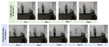
5.1.3 Camera 3
The imaging view of Camera 3 is primarily covered by the sensing ranges of CSI-1, CSI-3, CSI-7, and CSI-9 (although CSI-1 is not shown in the image, its positional relation to Camera 3 is similar to that of CSI-7). The results indicate that the best imaging performances ( in PSNR and in SSIM) are more likely to be obtained with the CSI from these sensors, as shown in Fig. 11 and Fig. 12. Using the CSI data collected from sensors outside the camera’s view results in a maximal degradation of image quality, with a decrease of about in PSNR and in SSIM.
Moreover, by calculating the average PSNR and SSIM for the nine CSI-guided imaging results on each camera dataset, we observe that Camera 3 (PSNR: , SSIM: ) achieves significantly better results than Camera 1 (PSNR: , SSIM: ) and Camera 2 (PSNR: , SSIM: ). This improvement may be because Camera 3 focuses on less than of the room’s space (a corner, actually), while Camera 1 and Camera 2 cover over of the room. As a result, Camera 3 requires less imagery information from CSI to visualize the environment.
5.2 Fusing CSI from Multiple Sensors
The preceding subsection demonstrated that while a single sensor’s CSI can yield precise imaging results when the sensor is near the imaging area, it has limitations in achieving a comprehensive perception and imaging of the entire environment.
To illustrate this issue, we refer to the experimental results shown in Fig. 15. From the viewpoint of Camera 2, two pedestrians can be observed moving at different distances, with one closer and the other farther away. Initially, we employ only the CSI data from CSI-7 for imaging, which is closer to the distant pedestrian ( or so). In this case, Trans-Inpainter successfully recovers the image of the distant pedestrian but fails to reconstruct the image of the closer pedestrian. However, by incorporating additional CSI data from CSI-1 and CSI-4, we resolve this problem, leading to a precise reconstruction of both pedestrians’ portraits. This observation leads us to conclude that the final imaging range results from the combination of the perceptual ranges of individual sensors. To achieve a complete reconstruction of an image taken by a camera, it is essential to utilize multiple sensors to ensure that the perceptual range of RF signals fully covers the entire camera view.
Furthermore, this conclusion explains the consistently better results obtained from Camera 3 in Section 4 compared to Cameras 1 and 2. Generally, Camera 3 captures images of only one person, while the other two capture images of two people. When using the CSI from a single sensor for imaging, it may lead to losing some portrait information, resulting in lower Mean PSNR and SSIM scores. This difference in imaging outcomes highlights the importance of using multiple sensors to achieve comprehensive and accurate image reconstruction.
5.3 Variation of CSI Matrix
The CSI matrix, representing the channel state over different subcarriers and time slots, undergoes variations in the time or frequency dimension, significantly impacting imaging performance.
5.3.1 Changes in the Time Dimension
In our previous work [5], we demonstrated the significance of selecting an appropriate number of RSSI values in a single time sequence to achieve effective image inpainting. Here, we explore the impact of varying the length () of the time sequence of the CSI matrix (ranging from to with an interval of 50) obtained from CSI-1, CSI-3, CSI-7, and CSI-9 for reconstructing Camera 3 images. The imaging results in Fig. 14 show a gradual improvement as the time window length increases, reaching its peak at around , followed by a gradual decline. This observation aligns with our findings in [5]. Surprisingly, clear imaging results can even be obtained with a CSI time dimension of 10 (), an achievement impossible with RSSI, reaffirming the superiority of CSI over RSSI in this context.
5.3.2 Subcarrier-dimension Compression
The frequency dimension indicates the number of subcarriers a WiFi channel with MIMO can be divided into using OFDM. While a higher number of subcarriers theoretically provides richer CSI information and better imaging performance, it also increases computational resources and time consumption, especially when imaging with CSI matrices from multiple sensors.
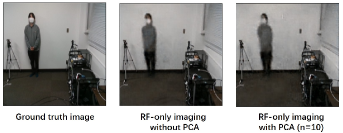
To achieve an effective and computationally friendly imaging task, we consider finding a balance between imaging performance and the frequency dimension of the CSI matrices. We perform Principal Component Analysis (PCA) on the frequency dimension of CSI matrices. PCA is a statistical technique used to reduce the dimensionality of a dataset by identifying its most essential features or components. In the context of CSI matrices, PCA can reduce the frequency dimension while retaining essential information about the wireless channel’s characteristics.
Our experimental results demonstrate the feasibility of this approach. Using CSI matrices from CSI-1, CSI-3, CSI-7, and CSI-9 to image from the viewpoint of Camera 3, we applied PCA to reduce the frequency dimension from 256 to 10, leading to a compression of hyper-parameters in Trans-Inpainter from 434,270,379 to 23,588,529 (a compression of ). Consequently, the training time of Trans-Inpainter decreased from to (a compression of ). Visually, as shown in Fig. 15, the imaging results were not significantly affected, with only a slight decrease in mean SSIM (from to ) and mean PSNR (from to ). This trade-off between imaging performance and computation time proves worthwhile, particularly when dealing with a substantial amount of training data.
6 Conclusion
In this paper, we present Trans-Inpainter, a novel multimodal image restoration method guided by CSI data to generate high-quality and realistic reconstructed images. Notably, this work is the first to explore extracting visual information from CSI time sequences using transformer architectures, benefiting from the transformer’s ability to handle temporal sequence data effectively. Our comprehensive evaluation compares Trans-Inpainter with the state-of-the-art RF-Inpainter under various challenging experimental scenarios. Additionally, we investigate single-modality image inpainting with only RF or image data for both Trans-Inpainter and RF-Inpainter. The results consistently demonstrate the superior performance of multimodal Trans-Inpainter across all cases.
Furthermore, we delve into the impact of varying CSI data on Trans-Inpainter’s imaging capability. Our experimental analysis includes studying the effects of using CSI data from individual sensors at different locations, fusing CSI from multiple sensors at various locations, and altering the temporal or frequency dimensions of the CSI matrix on CSI-based imaging results. These findings offer crucial insights and references for future wireless sensing studies, such as Wi-Fi-based imaging, motion recognition, and localization.
Although this study presents promising results, several avenues for future research can be explored. Firstly, adopting advanced transformer variants and architecture modifications may further enhance Trans-Inpainter’s performance. Additionally, exploring different fusion strategies to combine visual and temporal data and integrating other sensor modalities, such as LiDAR or audio information, could lead to even more robust and versatile image inpainting approaches. Furthermore, extending this research to real-world applications with diverse and complex environments, such as outdoor scenarios and dynamic scenes, would be of significant interest. Evaluating Trans-Inpainter’s performance in other wireless sensing tasks, such as motion tracking and localization, could also uncover its potential for broader applications in wireless communication and computer vision.
7 Acknowledgments
This work was supported in part by JSPS KAKENHI Grant Number JP22H03575.
References
- [1] J. Jam, C. Kendrick, K. Walker, V. Drouard, J. G.-S. Hsu, and M. H. Yap, “A comprehensive review of past and present image inpainting methods,” Computer Vision and Image Understanding, vol. 203, p. 103147, 2021.
- [2] X. Zhang, D. Zhai, T. Li, Y. Zhou, and Y. Lin, “Image inpainting based on deep learning: A review,” Information Fusion, vol. 90, pp. 74–94, 2023. [Online]. Available: https://www.sciencedirect.com/science/article/pii/S1566253522001324
- [3] Z. Qin, Q. Zeng, Y. Zong, and F. Xu, “Image inpainting based on deep learning: A review,” Displays, vol. 69, p. 102028, 2021.
- [4] T. Nishio, Y. Koda, J. Park, M. Bennis, and K. Doppler, “When wireless communications meet computer vision in beyond 5g,” IEEE Communications Standards Magazine, vol. 5, no. 2, pp. 76–83, 2021.
- [5] C. Chen, T. Nishio, M. Bennis, and J. Park, “Rf-inpainter: Multimodal image inpainting based on vision and radio signals,” IEEE Access, vol. 10, pp. 110 689–110 700, 2022.
- [6] Y. Deng, S. Hui, S. Zhou, D. Meng, and J. Wang, “Learning contextual transformer network for image inpainting,” in Proc. ACM Multimedia, Chengdu, China, 2021, pp. 2529–2538.
- [7] J. Pirnay and K. Chai, “Inpainting transformer for anomaly detection,” in Proc.ICIAP, Lecce, Italy, 2022, pp. 394–406.
- [8] R. Girdhar, A. El-Nouby, Z. Liu, M. Singh, K. V. Alwala, A. Joulin, and I. Misra, “Imagebind: One embedding space to bind them all,” in Proc. IEEE CVPR, Vancouver, Canada, 2023, pp. 15 180–15 190.
- [9] Z. Liu, H. Mao, C.-Y. Wu, C. Feichtenhofer, T. Darrell, and S. Xie, “A convnet for the 2020s,” in Proc. IEEE CVPR, New Orleans, LA, USA, June 2022, pp. 11 976–11 986.
- [10] Z. Yang, Z. Zhou, and Y. Liu, “From rssi to csi: Indoor localization via channel response,” ACM Computing Surveys (CSUR), vol. 46, no. 2, pp. 1–32, 2013.
- [11] F. Li, M. A. A. Al-Qaness, Y. Zhang, B. Zhao, and X. Luan, “A robust and device-free system for the recognition and classification of elderly activities,” Sensors, vol. 16, no. 12, p. 2043, 2016.
- [12] H. Xiang, Q. Zou, M. A. Nawaz, X. Huang, F. Zhang, and H. Yu, “Deep learning for image inpainting: A survey,” Pattern Recognition, vol. 134, p. 109046, 2023.
- [13] D. Pathak, P. Krahenbuhl, J. Donahue, T. Darrell, and A. A. Efros, “Context encoders: Feature learning by inpainting,” in Proc. IEEE CVPR, Las Vegas, NV, USA, 2016, pp. 2536–2544.
- [14] J. Yu, Z. Lin, J. Yang, X. Shen, X. Lu, and T. S. Huang, “Generative image inpainting with contextual attention,” in Proceedings of the IEEE conference on computer vision and pattern recognition, 2018, pp. 5505–5514.
- [15] G. Liu, F. A. Reda, K. J. Shih, T.-C. Wang, A. Tao, and B. Catanzaro, “Image inpainting for irregular holes using partial convolutions,” in Proc. ECCV, Munich, Germany, 2018, pp. 85–100.
- [16] C. Xie, S. Liu, C. Li, M.-M. Cheng, W. Zuo, X. Liu, S. Wen, and E. Ding, “Image inpainting with learnable bidirectional attention maps,” in Proc. IEEE ICCV, Seoul, Korea (South), 2019, pp. 8858–8867.
- [17] K. Nazeri, E. Ng, T. Joseph, F. Qureshi, and M. Ebrahimi, “Edgeconnect: Structure guided image inpainting using edge prediction,” in Proc. IEEE ICCVW, Seoul, Korea (South), 2019, pp. 0–0.
- [18] L. Liao, J. Xiao, Z. Wang, C.-W. Lin, and S. Satoh, “Image inpainting guided by coherence priors of semantics and textures,” in Proc. IEEE CVPR, Nashville, TN, USA, 2021, pp. 6539–6548.
- [19] Y. Ren, X. Yu, R. Zhang, T. H. Li, S. Liu, and G. Li, “Structureflow: Image inpainting via structure-aware appearance flow,” in Proc. IEEE ICCV, Seoul, Korea (South), 2019, pp. 181–190.
- [20] Y. Zeng, Z. Lin, J. Yang, J. Zhang, E. Shechtman, and H. Lu, “High-resolution image inpainting with iterative confidence feedback and guided upsampling,” in Proc. ECCV, Glasgow, UK, 2020, pp. 1–17.
- [21] H. Liu, B. Jiang, Y. Song, W. Huang, and C. Yang, “Rethinking image inpainting via a mutual encoder-decoder with feature equalizations,” in Proc. ECCV, Glasgow, UK, 2020, pp. 725–741.
- [22] J. Yang, Z. Qi, and Y. Shi, “Learning to incorporate structure knowledge for image inpainting,” in Proc. AAAI, vol. 34, no. 07, New York, USA, 2020, pp. 12 605–12 612.
- [23] H. Liu, B. Jiang, Y. Xiao, and C. Yang, “Coherent semantic attention for image inpainting,” in Proc. IEEE ICCV, Seoul, Korea (South), 2019, pp. 4170–4179.
- [24] N. Wang, J. Li, L. Zhang, and B. Du, “Musical: Multi-scale image contextual attention learning for inpainting.” in Proc. IJCAI, Macao, China, 2019, pp. 3748–3754.
- [25] Y. Zeng, J. Fu, H. Chao, and B. Guo, “Learning pyramid-context encoder network for high-quality image inpainting,” in Proc. IEEE CVPR, Long Beach, CA, USA, 2019, pp. 1486–1494.
- [26] W. Li, Z. Lin, K. Zhou, L. Qi, Y. Wang, and J. Jia, “Mat: Mask-aware transformer for large hole image inpainting,” in Proc. IEEE CVPR, New Orleans, LA, USA, 2022, pp. 10 758–10 768.
- [27] A. Ramesh, M. Pavlov, G. Goh, S. Gray, C. Voss, A. Radford, M. Chen, and I. Sutskever, “Zero-shot text-to-image generation,” in Proc. ICML, 2021, pp. 8821–8831.
- [28] M. Ding, Z. Yang, W. Hong, W. Zheng, C. Zhou, D. Yin, J. Lin, X. Zou, Z. Shao, H. Yang et al., “Cogview: Mastering text-to-image generation via transformers,” Advances in Neural Information Processing Systems, vol. 34, pp. 19 822–19 835, 2021.
- [29] C. Saharia, W. Chan, S. Saxena, L. Li, J. Whang, E. L. Denton, K. Ghasemipour, R. Gontijo Lopes, B. Karagol Ayan, T. Salimans, J. Ho, D. J. Fleet, and M. Norouzi, “Photorealistic text-to-image diffusion models with deep language understanding,” in Proc. NeurIPS, S. Koyejo, S. Mohamed, A. Agarwal, D. Belgrave, K. Cho, and A. Oh, Eds., vol. 35, New Orleans, Louisiana, USA, 2022, pp. 36 479–36 494.
- [30] Q. Lin, B. Yan, J. Li, and W. Tan, “Mmfl: Multimodal fusion learning for text-guided image inpainting,” in Proc. ACM Multimedia, Seattle, USA, 2020, pp. 1094–1102.
- [31] L. Zhang, Q. Chen, B. Hu, and S. Jiang, “Text-guided neural image inpainting,” in Proc. ACM Multimedia, Seattle, USA, 2020, pp. 1302–1310.
- [32] M. Ni, C. Wu, H. Huang, D. Jiang, W. Zuo, and N. Duan, “NÜwa-lip: Language guided image inpainting with defect-free vqgan,” arXiv preprint arXiv:2202.05009, 2022.
- [33] A. Li, L. Zhao, Z. Zuo, Z. Wang, W. Xing, and D. Lu, “Migt: Multi-modal image inpainting guided with text,” Neurocomputing, vol. 520, pp. 376–385, 2023.
- [34] Y. He, Y. Chen, Y. Hu, and B. Zeng, “Wifi vision: Sensing, recognition, and detection with commodity mimo-ofdm wifi,” IEEE Internet of Things Journal, vol. 7, no. 9, pp. 8296–8317, 2020.
- [35] S. Kato, T. Fukushima, T. Murakami, H. Abeysekera, Y. Iwasaki, T. Fujihashi, T. Watanabe, and S. Saruwatari, “Csi2image: Image reconstruction from channel state information using generative adversarial networks,” IEEE Access, vol. 9, pp. 47 154–47 168, 2021.
- [36] Y. Ma, G. Zhou, and S. Wang, “Wifi sensing with channel state information: A survey,” ACM Computing Surveys (CSUR), vol. 52, no. 3, pp. 1–36, 2019.
- [37] A. Vaswani, N. Shazeer, N. Parmar, J. Uszkoreit, L. Jones, A. N. Gomez, Ł. Kaiser, and I. Polosukhin, “Attention is all you need,” Advances in neural information processing systems, vol. 30, 2017.
- [38] A. Dosovitskiy, L. Beyer, A. Kolesnikov, D. Weissenborn, X. Zhai, T. Unterthiner, M. Dehghani, M. Minderer, G. Heigold, S. Gelly, J. Uszkoreit, and N. Houlsby, “An image is worth 16x16 words: Transformers for image recognition at scale,” in Proc. ICLR, Vienna, Austria, 2021.
- [39] Z. Liu, Y. Lin, Y. Cao, H. Hu, Y. Wei, Z. Zhang, S. Lin, and B. Guo, “Swin transformer: Hierarchical vision transformer using shifted windows,” in Proc. IEEE ICCV, Montreal, QC, Canada, 2021, pp. 10 012–10 022.
- [40] J. Liang, J. Cao, G. Sun, K. Zhang, L. Van Gool, and R. Timofte, “Swinir: Image restoration using swin transformer,” in Proc. IEEE ICCV, Montreal, QC, Canada, 2021, pp. 1833–1844.
- [41] A. Tirumala, “Iperf: The TCP/UDP bandwidth measurement tool,” 1999. [Online]. Available: https://iperf.fr
- [42] F. Gringoli, M. Schulz, J. Link, and M. Hollick, “Free your CSI: A channel state information extraction platform for modern Wi-Fi chipsets,” in Proc. ACM WiNTECH, Los Cabos, Mexico, 2019, p. 21–28.
![[Uncaptioned image]](/html/2305.05385/assets/figs/Cheng_Chen.jpg) |
Cheng Chen received the B.E. degree in Information and Communications Engineering (ICE) from the National University of Defence Technology in 2019 and the master’s degree in ICE from Tokyo Institute of Technology in 2023. He received the Outstanding Student Award from the Department of ICE in 2023 and is currently undertaking a Ph.D. at Tokyo Institute of Technology. |
![[Uncaptioned image]](/html/2305.05385/assets/figs/Shoki_Ohta.jpg) |
Shoki Ohta (Student Member, IEEE) received the B.E. degree in Information and Communications Engineering from Tokyo Institute of Technology in 2022. He is currently studying toward the M.E. degree at the School of Engineering, Tokyo Institute of Technology. He received the IEEE Vehicular Technology Society (VTS) Japan Young Researcher’s Encouragement Award in 2022. |
![[Uncaptioned image]](/html/2305.05385/assets/figs/Takayuki_Nishio.jpg) |
Takayuki Nishio (Senior Member, IEEE) received the B.E. degree in electrical and electronic engineering and the master’s and Ph.D. degrees in informatics from Kyoto University, in 2010, 2012, and 2013, respectively. He was an Assistant Professor in communications and computer engineering at the Graduate School of Informatics, Kyoto University, from 2013 to 2020. From 2016 to 2017, he was a Visiting Researcher at the Wireless Information Network Laboratory (WINLAB), Rutgers University, USA. Since 2020, he has been an Associate Professor at the School of Engineering, Tokyo Institute of Technology, Japan, and the Wireless Information Network Laboratory (WINLAB), Rutgers University. His current research interests include machine learning-based network control, machine learning in wireless networks, vision-aided wireless communications, and heterogeneous resource management. |
![[Uncaptioned image]](/html/2305.05385/assets/figs/Mehdi_Bennis.jpg) |
Mehdi Bennis (Fellow, IEEE) is currently a Professor with the Centre for Wireless Communications, University of Oulu, Finland, an Academy of Finland Research Fellow, and the Head of the Intelligent Connectivity and Networks/Systems Group (ICON). He has published over 200 research papers in international conferences, journals, and book chapters. His main research interests include radio-resource management, heterogeneous networks, game theory, and distributed machine learning in 5G networks and beyond. He has been a recipient of several prestigious awards, including the 2015 Fred W. Ellersick Prize from the IEEE Communications Society, the 2016 Best Tutorial Prize from the IEEE Communications Society, the 2017 EURASIP Best Paper Award for the Journal of Wireless Communications and Networking, the University of Oulu Award for Research, the 2019 IEEE ComSoc Radio Communications Committee Early Achievement Award, and the 2020 Clarviate Highly Cited Researcher from the Web of Science. He is also an editor of IEEE Transactions on Communications (TCOM) and the Specialty Chief Editor for Data Science for Communications in the Frontiers in Communications and Networks journal. |
![[Uncaptioned image]](/html/2305.05385/assets/figs/Jihong_Park.jpg) |
Jihong Park (Senior Member, IEEE) is a Lecturer with the School of Information Technology, Deakin University, Australia. He received his B.S. and Ph.D. degrees from Yonsei University, Seoul, South Korea, in 2009 and 2016, respectively. He was a Postdoctoral Researcher at Aalborg University, Denmark, from 2016 to 2017, and the University of Oulu, Finland, from 2018 to 2019. His current research interests include AI-native and semantic communications, as well as distributed and quantum machine learning. He is a Member of ACM and AAAI. He has served as a Program Committee Member for several conferences and workshops, including IEEE GLOBECOM, ICC, and INFOCOM, as well as NeurIPS, ICML, and IJCAI. He has organized workshops at IEEE GLOBECOM, WCNC, VTC, and SECON. He has received 2023 IEEE Communication Society Heinrich Hertz Award, 2022 FL-IJCAI Best Student Paper Award, 2014 IEEE GLOBECOM Student Travel Grant, 2014 IEEE Seoul Section Student Paper Prize, and 2014 IDIS-ETNEWS Paper Award. Currently, he is the co-chair for 2023 IEEE GLOBECOM Symposium on Machine Learning for Communications, and an Associate Editor of Data Science for Communications (Frontiers) and Signal Processing for Communications (Frontiers). |
![[Uncaptioned image]](/html/2305.05385/assets/figs/Wahib_Mohamed.jpg) |
Mohamed Wahib is a team leader of the “High-Performance Artificial Intelligence Systems Research Team” at RIKEN Center for Computational Science (R-CCS), Kobe, Japan. Prior to that he worked as is a senior scientist at AIST/TokyoTech Open Innovation Laboratory, Tokyo, Japan. He received his Ph.D. in Computer Science in 2012 from Hokkaido University, Japan. His research interests revolve around the central topic of high-performance programming systems, in the context of HPC and AI. He is actively working on several projects including high-level frameworks for programming traditional scientific applications, as well as high-performance AI. |