itemizestditemize
Hydra-Multi: Collaborative Online Construction of
3D Scene Graphs with Multi-Robot Teams
Abstract
3D scene graphs have recently emerged as an expressive high-level map representation that describes a 3D environment as a layered graph where nodes represent spatial concepts at multiple levels of abstraction (e.g., objects, rooms, buildings) and edges represent relations between concepts (e.g., inclusion, adjacency). This paper describes Hydra-Multi, the first multi-robot spatial perception system capable of constructing a multi-robot 3D scene graph online from sensor data collected by robots in a team. In particular, we develop a centralized system capable of constructing a joint 3D scene graph by taking incremental inputs from multiple robots, effectively finding the relative transforms between the robots’ frames, and incorporating loop closure detections to correctly reconcile the scene graph nodes from different robots. We evaluate Hydra-Multi on simulated and real scenarios and show it is able to reconstruct accurate 3D scene graphs online. We also demonstrate Hydra-Multi’s capability of supporting heterogeneous teams by fusing different map representations built by robots with different sensor suites.
I Introduction
Multi-robot systems have become increasingly popular both in the robotics research community and in the industry at large due to their capability to sense and act over large-scale environments. Multi-robot operation is important for applications such as factory automation, intelligent transportation, disaster response, and environmental monitoring, to name a few.
In this work, we address the problem of using a team of robots to gain situational awareness over a large environment. In particular, we develop a system that allows robots in a team to build a high-level map representation, namely a 3D scene graph. A 3D scene graph is a hierarchical graph where nodes represent spatial concepts at multiple levels of abstraction (e.g., objects, rooms, and buildings for indoor environments), and edges represent relations between concepts (e.g., inclusion or adjacency). This representation has been recently proposed as a high-level representation of 3D environments [1, 2, 3, 4, 5], and has been successfully used for hierarchical planning and object search [3, 6]. Our goal is to collaboratively estimate a 3D scene graph of the environment that describes the spatial and semantic information of the scene the robots operate in.
3D scene graphs are particularly suitable for multi-robot operation, since they enable fast planning and decision-making over the large-scale environments often covered by multi-robot teams. Moreover, as shown in our experiments, their layered structure makes it easy to reconcile heterogeneous map representations, e.g., built by robots using different sensor suites or relying on different mapping pipelines.
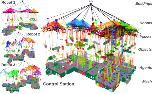
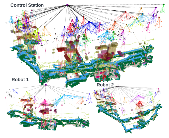
Contribution. The main contribution of this paper is the development of Hydra-Multi (Fig. 1), the first multi-robot spatial perception system capable of building a hierarchical 3D scene graph online from sensor data. The system builds on top of Hydra [4] and its main features include: (i) a 3D-scene-graph-based hierarchical loop closure detection module based on [4], which enables a more versatile inter-robot loop closure detection; (ii) a frame alignment module that removes the need to calibrate the initial poses of the robots; (iii) an align-optimize-reconcile framework that uses Graduated Non-Convexity (GNC) [7] to optimize multi-robot 3D scene graphs while being robust to outlier loop closures and erroneous associations of scene graph nodes across different robots.
We evaluate Hydra-Multi both in simulation and with a team of robots mapping two student residences. Our experiments show that (i) we can reconstruct a centralized 3D scene graph of large indoor environments with multiple robots online, (ii) our multi-robot system achieves performance comparable to the single-robot system [4], while enabling faster mapping, (iii) our system is robust to perceptual aliasing and is able to accurately find the global frame for all the robots in the team without any initial calibration, and then correctly reconcile and merge the 3D scene graphs obtained from each robot, and (iv) our system can effectively merge different map representations produced by a team of heterogeneous robots.
II Related Work
Multi-Robot SLAM. Many multi-robot SLAM systems can be split into a frontend for intra and inter-robot loop closure detection and a backend which typically performs pose-graph or factor-graph optimization [8, 9]. The literature on multi-robot SLAM can be similarly divided into works that focus on the frontend, the backend, or the system as a whole.
In a centralized setup, a common way to obtain loop closures is to use visual place recognition methods [10, 11, 12, 13, 14, 15]. Some recent works also focus on designing a distributed multi-robot frontend to find loop closures via local communication among the robots [16, 17, 18, 19, 20, 21]. Centralized backend approaches collect measurements at a central server, which computes the trajectory estimates for all robots [22, 23, 24, 25, 26]. Distributed backend approaches, on the other hand, distribute the pose graph optimization task among the robots [27, 28, 29, 30, 31]. A number of recent papers develop complete systems for localization and mapping, such as [16, 27, 32, 33, 34, 35, 36]. However, there is only a sparse set of works that aims at enabling multi-robot systems to construct higher-level metric-semantic representations: [37, 38] present a distributed multi-robot system that constructs semantically labeled 3D meshes of the environment, while [39] demonstrates a system where ground robots localize in a semantic map created in real time by a high-altitude quadrotor by semantically matching local maps with the overhead map for cross-view localization.
Metric-semantic and Hierarchical Mapping. Spatial AI [40] is a concept proposed to build perception systems that allow a robot to more effectively interact with its environment. This idea of building maps that are more compatible with high-level tasks assigned to a robot, along with the new possibilities from deep learning and the maturity of traditional 3D reconstruction and SLAM techniques, gave rise to a surge in interest towards metric-semantic and hierarchical mapping. The literature includes approaches to build maps based on objects [41, 42, 43, 44, 45, 46], volumetric models [47, 48, 49], point clouds [50, 51, 52], 3D meshes [53, 54], hierarchies [55, 56, 57, 58, 59, 60, 61], and combinations thereof [62, 63, 64, 65]. More recently, 3D scene graphs have been proposed as expressive hierarchical models of the environment [1, 3]. The approaches in [1, 3, 2] are designed for offline use, while Wu et al. [5], Hughes et al. [4], and Bavle et al. [66, 67] have recently demonstrated online construction of 3D scene graphs.
III Hydra-Multi
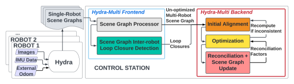
The architecture of the proposed spatial perception system, dubbed Hydra-Multi, is shown in Fig. 2. It consists of a frontend for interfacing the centralized control station with the individual robots and for loop closure detection, and a backend for scene graph optimization and reconciliation. In this section, we discuss each component of Hydra-Multi.
III-A Hydra-Multi Frontend
Each robot runs a local instance of Hydra [4] to build a local 3D scene graph of the portion of the environment it has explored. The Hydra-Multi frontend, running at the control station, receives the latest scene graphs from the individual robots, and is also in charge of detecting loop closures between the robots (i.e., inter-robot loop closures).
Scene Graph Processor. The partial single-robot 3D scene graphs are first collected into a single un-optimized and un-reconciled frontend scene graph. The frontend scene graph is un-optimized in that it might suffer from large drift since it does not include inter-robot loop closures; it might even include scene graphs that do not share a common reference frame (see discussion about Initial Alignment below). Moreover, it is un-reconciled, since it might have many duplicated nodes (e.g., multiple nodes corresponding to the same object observed by different robots). When the control station receives the latest scene graph from a robot (the entire scene graph is transmitted periodically from each robot to the control station), new nodes and edges are added, and the nodes and edges that were deleted on the robot scene graph are also removed from the frontend scene graph. Careful book-keeping is done on tracking the reference frame of each node for the initial alignment step in the backend. The frontend scene graph is kept separate from the backend scene graph, which instead is optimized and reconciled at each iteration.
Loop Closure Detection. To search for inter-robot loop closures, we apply the hierarchical loop closure detection method described in [4] to the multi-robot frontend scene graph. The method consists of a Top-down Loop Closure Detection step that compares scene-graph-based descriptors computed across different layers of the frontend scene graph (from places, which are representations of free space in the environment, to objects, to visual appearance descriptors), and a Bottom-up Geometric Verification step that attempts to register the matches at each layer with RANSAC (for visual keypoints) or TEASER++ [68] (for object nodes).
III-B Hydra-Multi Backend
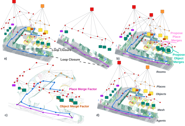
The backend is in charge of optimizing the frontend scene graph into a globally consistent and unified representation, and reconciling redundant nodes in regions of the environment observed by multiple robots. Towards this goal, the Hydra-Multi backend performs the series of operations shown in Fig. 3. These steps include (i) finding an initial frame alignment using the detected inter-robot loop closures, (ii) proposing node reconciliations based on overlapping nodes after initial alignment, (iii) performing robust pose-graph optimization using an embedded deformation graph, and (iv) merging the valid reconciled nodes. We explain each step below.
Initial Alignment. In this step we estimate a common reference frame for all robots, which we use to transform all the local 3D scene graphs into a common frame in preparation for 3D scene graph optimization. To compute an initial multi-robot alignment, we follow the approach proposed in [38] by first choosing an arbitrary spanning tree in the robot-level dependence graph [29], where the nodes of the graph represent the robots and the edges correspond to the inter-robot loop closures, and then estimating the relative pose between pairs of robots corresponding to the edges in the spanning tree.
To estimate the relative pose between the reference frames of two robots, say and , we take each inter-robot loop closure —where is the node corresponding to the pose of robot at time , and corresponds to the pose of robot at time — and obtain a noisy estimate of the pose of the reference frame of with respect to as
| (1) |
where and are the odometric estimates of the poses of nodes and , and is the loop closure measurement.
After computing the relative transformation between the robots for each inter-robot loop closure, we obtain a set of noisy relative transformation estimates. In order to obtain a reliable estimate of the true relative transformation, we formulate and solve the following robust pose averaging problem,
| (2) |
where is the truncated least squares (TLS) robust cost function [7], is the set of inter-robot loop closures between robots and , and for two poses and , we use the standard notation to denote the tangent-space representation of the relative pose . For a vector , we also use the standard notation for the Mahalanobis distance. In (2), is a fixed covariance matrix and each residual measures the geodesic distance between the to-be-computed average pose and the measurement . In practice, we solve (2) using the GNC [7] implementation available in GTSAM [69].
We count a robot as initialized if there are at least inliers detected by GNC ( in our tests). By chaining the relative poses obtained from (2) along the spanning tree, we obtain transforms from each robot’s local frame to the global frame (conventionally set to be the reference frame of one of the robots). We then apply this estimated transform to the nodes of the 3D scene graph of each robot to obtain the initial guess for multi-robot 3D scene graph optimization. Once the global frame for a robot is computed we do not re-compute the initial alignment after detecting more inter-robot loop closures, unless there is a distinct disagreement with the result of the multi-robot scene graph optimization, i.e., if the distance between the relative translation estimate from the initial alignment and the corresponding translation computed from the result of the 3D scene graph optimization (discussed below) is greater than a threshold (m in our tests).
Reconciliation Proposal. Based on the results of the initial alignment, we identify merge candidates for pairs of place and object nodes. Place merges are proposed if two place nodes overlap (e.g., have distance m) and have similar sizes (e.g., difference between radii m). Object merges are proposed if two objects have the same semantic label and overlapping bounding boxes. We only propose as merge candidates nodes belonging to initialized robots. The places merge candidates are added to the deformation graph (see below) as relative pose factors with identity transform. The transform for the object merge candidates is first determined by running ICP on the corresponding mesh vertices, and then added to the deformation graph for scene graph optimization.
Robust Scene Graph Optimization. Given the partial single-robot scene graphs, the merge candidates, and the inter-robot loop closures, the backend scene graph is optimized using an embedded deformation graph approach [70]. The embedded deformation graph approach associates a local frame (i.e., a pose) to a subset of nodes in the scene graph and then solves an optimization problem to adjust the local frames in a way that minimizes deformations associated to each edge (including loop closures). The deformation graph can be seen as the factor graph representation of the 3D scene graph, and the optimization minimizes edges potentials.
More in detail, from the multi-robot scene graph, the nodes on the agent layer (corresponding to the robot’s trajectory), the places layer, and objects that are proposed as merge candidates are added as nodes to the deformation graph, while a subset of the vertices of the 3D mesh reconstructed by each robot is added as control point vertices to the deformation graph. Then, the configuration of these poses is estimated by minimizing a cost that captures (i) odometry and loop closure measurements, (ii) local rigidity of the 3D meshes, (iii) reconciliation factors corresponding to merge candidates between nodes of different robots. As shown in [3], assuming rigid transformations for each frame, deformation graph optimization can be formulated as a pose-graph optimization problem:
| (3) |
where is the to-be-estimated pose of each frame in the deformation graph, and are the edges in the deformation graph, which correspond to odometric measurements, loop closures, and merge candidates. We solve (3) using GNC [7] in GTSAM [71], in order to reject spurious loop closures and incorrect merge candidates as outliers.
Node Reconciliation. Once the optimization is finished, the place nodes are updated with their new positions and the full mesh is interpolated from the new control vertices [70]. We then recompute the object centroids and bounding boxes from the position of the corresponding vertices in the newly deformed mesh [4]. A merge candidate is considered valid if it is selected as an inlier by GNC. After the valid merges are identified, we compare the number of valid merges with the number of proposed merges, and we undo all merges in the scene graph if the ratio is below a certain threshold ( in our experiments). Finally, we segment rooms from the merged places using the room segmentation approach described in [4].
III-C Hydra-Multi with Heterogeneous Teams
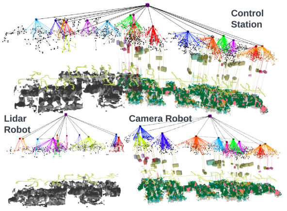
The assumed default configuration for each robot in the Hydra-Multi system relies on visual-inertial odometry as the localization backbone, and uses RGB-D data for 3D mapping. In case a robot with a different sensor or mapping suite is added to the team, we are still able to support the robot and merge its local map into the Hydra-Multi scene graph, as long as the robot map representation is compatible with at least one layer in the scene graph. For instance, if a robot performs object-based SLAM with a stereo camera, we can fuse the objects it detects into the object layer of the scene graph. Similarly, if a robot is equipped with a LIDAR and builds a mesh without semantic annotations, we can fuse the mesh and the corresponding graph of places in the scene graph. In other words, the multi-layered nature of the 3D scene graph enables the fusion of heterogeneous maps (Fig. 4).
IV Experiments
This section demonstrates that Hydra-Multi builds accurate 3D scene graphs online using inputs from multiple (possibly heterogeneous) robots, and provides an ablation of the contribution of each module to the performance of the system.
IV-A Experimental Setup
Datasets. We use three datasets for our experiments: uHumans2 (uH2), SidPac (SP), and Simmons (SM). The uH2 dataset [3] is a Unity-based simulated dataset that provides visual-inertial data, as well as ground-truth depth and 2D semantic segmentation. In particular, we test Hydra-Multi on three sequences from a single-floor office environment.
The SP dataset is a real-world dataset collected in a graduate student housing building using a visual-inertial hand-held device as described in [4]. We test Hydra-Multi by treating two separate recordings as two different robots. These scenes are particularly challenging given their scale (average traversal of around 400 meters), with one recording covering floor 1 and floor 3 of the building and the other covering floor 3 and floor 4 of the building; moreover, the robots start on different floors, providing a unique challenge in terms of finding the correct relative transforms between the two robots. The proxy ground-truth trajectory for this dataset is generated via hand-tuned pose-graph optimization as described in [4].
The SM dataset is a real world dataset collected in an undergraduate student housing building using two Clearpath Jackal robots equipped with an Intel Realsense D455 camera and a LIDAR. This dataset is challenging due to its scale (average traversal of around 500 meters), and the presence of perceptual aliasing in loop closure detection, caused by visual and structural similarity across different rooms (e.g., student rooms have similar layout and identical furniture), which leads the frontend to detect up to to outlier loop closures. Additionally, the robots traverse cluttered rooms and tight spaces, which provide a challenge for Hydra and Hydra-Multi. The proxy ground-truth robot trajectories for this dataset are obtained by running a LIDAR SLAM pipeline with flat ground assumption [72, 33].
Hydra-Multi System. For all the datasets, we use the RGB-D version of Kimera-VIO [3] for visual-inertial odometry. For SP, we fuse the Kimera-VIO estimates with the RealSense T265 camera’s builtin visual odometry to improve the quality of the trajectory estimate. However, this is still our most challenging dataset due to unfavorable lighting, prevalence of glass (causing partial and noisy depth estimates from the RGB-D camera), feature-poor regions in hallways, and the lack of other types of sensors to improve the odometry estimate. For SM, we fuse the Kimera-VIO estimates with the Jackal wheel odometry and LIDAR odometry [72], to improve the odometry in the presence of reflective surfaces and large windows.
For SP, we use HRNet [73] for 2D semantic segmentation while for SM, we use OneFormer [74], which provides a cleaner segmentation from the low viewpoint of the Jackal robots moving in cluttered environments.
The Hydra-Multi system described in Section III is implemented in C++ and ROS. The experiments are performed on a workstation with a 12-core Intel i9 processor and 2 Nvidia Titan RTX GPUs.
IV-B Results
Localization Error. We show that Hydra-Multi achieves a localization accuracy comparable to state-of-the-art vision-based and LIDAR-based SLAM pipelines, by comparing it against the system presented in [33] (LAMP 2.0) using the recorded LIDAR and wheel odometry as input, and against a centralized version of the system presented in [38] (Kimera-Multi) using the same sensor configurations as the Hydra-Multi system. The results are shown in Table I. Hydra-Multi leads to slightly better errors compared to the Kimera-Multi pipeline, thanks to the hierarchical loop closure detection and the places and object reconciliation. For the datasets where robots were equipped with LIDAR sensors (SM1, SM2), the performance of Hydra-Multi remains close to the performance achieved by the LIDAR-based pipeline.
| uH2 | SP | SM1 | SM2 | |
|---|---|---|---|---|
| Kimera-Multi [38] | 0.59 0.01 | 4.99 1.42 | 2.0 0.18 | 0.87 0.22 |
| LAMP 2.0 [33] | - | - | 0.73 0.4 | 0.58 0.03 |
| Hydra-Multi | 0.25 0.05 | 3.92 0.9 | 0.99 0.31 | 0.79 0.15 |
Objects, Places, and Rooms. To evaluate Hydra-Multi’s ability to estimate higher-level abstractions, we first construct a ground-truth scene graph for each dataset. First, the ground-truth or proxy ground-truth trajectories for each dataset are rigidly aligned to the first robot’s reference frame via a hand-tuned ICP registration of the robots’ 3D meshes. Then, we use the aligned ground-truth trajectories for each dataset to reconstruct an Euclidean Signed Distance Function (ESDF) and a Generalized Voronoi Diagram (GVD), which we use to examine the accuracy of the places layer, and a 3D metric-semantic mesh, which we use to extract object locations and bounding boxes. Ground-truth room bounding-boxes are hand-labeled using the 3D metric semantic mesh for each dataset.
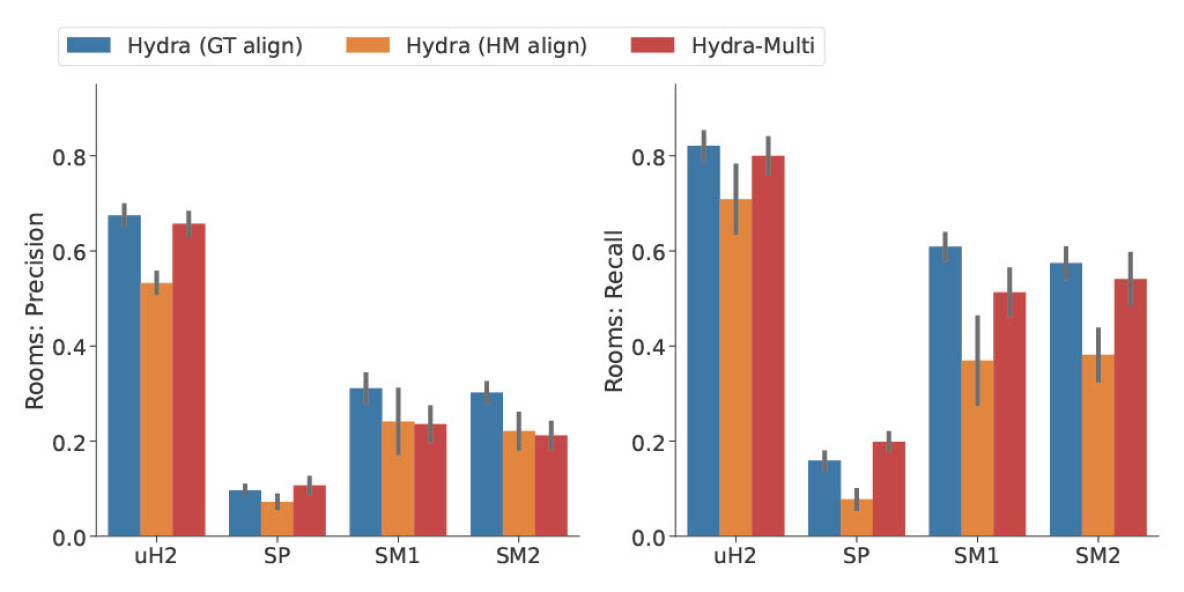
We consider the same performance metrics used in [4]. For the objects, we consider two metrics: % Correct is the percentage of object nodes in the estimated scene graph that are within a given distance threshold from the corresponding ground-truth object, and % Found is the percentage of ground-truth objects that are within a given distance threshold111m for uH2, m for SP, and m for SM based on size of scene and ATE. from the object nodes in the estimated scene graph. For the places, we record the distance of each place node in the scene graph being analyzed to the nearest voxel in the GVD, which we refer to as the Position Error. Finally, we report two metrics for the rooms using the free-space voxels contained within each ground-truth or estimated room. The first is Precision: the maximum number of overlapping voxels between any ground-truth room and the estimated room node being analyzed. The second is Recall: the maximum number of overlapping voxels between any estimated room and the ground-truth room being analyzed. These are averaged across all rooms being analyzed.
We compare Hydra-Multi against two baselines: (i) GT align, obtained by combining the single-robot scene graphs after aligning them to the ground truth trajectory: this represents the results we would obtain if we did not fuse the results in a centralized map, but rather had each robot explore in isolation after carefully calibrating their initial reference frames; (ii) HM align, obtained by combining the single-robot scene graphs after transformation to the global reference frame using the initial alignment from Hydra-Multi: this represents the results we would obtain when each robot maps on its own, but the robots are not initially calibrated.
We run five trials of Hydra-Multi on each dataset and show the resulting objects and places metrics in Fig. 8 and the room metrics in Fig. 9. In all datasets, we show that the performance of Hydra-Multi is comparable with that of single-robot Hydra with ground-truth alignment (GT align) despite not having any initial knowledge of the global reference frame; it is also consistently better than single-robot Hydra with the estimated initial alignment (HM align), which underlines the effectiveness of the scene graph optimization. In uH2 and SP, we even see a slight improvement in performance obtained by Hydra-Multi as compared to the GT align baseline, which results from the inter-robot loop closures in Hydra-Multi.
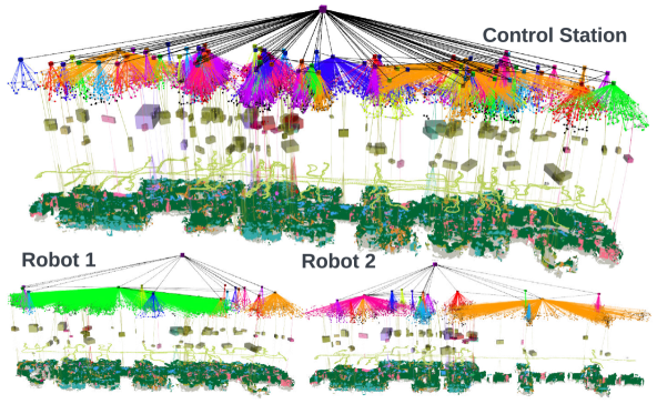
Qualitative results for the uH2 dataset are shown in Fig. 1, while the SP and SM datasets are shown in Figs. 5-7. In SM1 (Fig. 6), the robots started from different rooms on the same floor of the student dormitory and explored different parts of the scene. In SM2 (Fig. 7), the robots started from different rooms on opposite ends of the floor and rendezvoused in the middle. In both scenarios, Hydra-Multi was successful at reconstructing a 3D scene graph of the complete floor in around minutes. Note that covering similar trajectories sequentially using a single robot takes around minutes, restating the advantage of multi-robot operation.


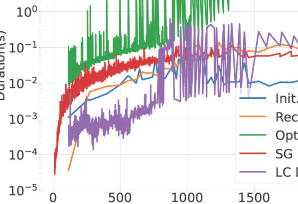
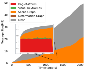
Bandwidth Usage and Runtime. The runtime of the different components of Hydra-Multi for a single run on the SM dataset is shown in Fig. 10(a). The Hydra-Multi frontend time per iteration remains bounded around 100ms, while the backend optimization time increases as the size of the graph grows. Since the frontend and backend run in parallel threads, the Hydra-Multi frontend is still able to run in real-time, but the corrections resulting from loop closures must wait for the backend optimization to finish and typically lag behind. Fig. 10(b) shows a breakdown of the bandwidth usage. Most of the bandwidth is consumed by transmitting the mesh and the scene graph, since the current system naively sends the entire scene graph from each robot to the control station at every update; the bandwidth usage for transmitting additional information for loop closure detection (bag-of-word descriptors, features for each keyframe) and inputs to the deformation graph optimization (deformation graph) —whose computation is entrusted to each robot— remains below 1MB.
Components Ablation. We evaluate the contribution of each component in the backend by running three variants of Hydra-Multi: (i) without reconciliation proposals (label “No Rec”), (ii) without initial alignment (label “No IA”), and (iii) with all proposed features (label “Full”). We compare the two object metrics (% Found and % Correct) for each variant across 5 trials in Table II. Running with all the components gives the best and most consistent result. Running without reconciliation produces fewer factors in the optimization to fully align the scene graphs from the two robot, resulting in a slight accuracy degradation. Running without initial alignment means that we do not have a good initialization for scene graph optimization, which largely degrades the results.
| uH2 | SP | SM1 | SM2 | ||
|---|---|---|---|---|---|
| No IA | Found (%) | 80.8 7.4 | 21.4 12.9 | 23.8 16.6 | 27.3 24.8 |
| Correct (%) | 90.0 6.6 | 36.8 20.5 | 16.2 10.1 | 26.6 24.1 | |
| No Rec | Found (%) | 91.1 0.4 | 29.1 13.0 | 37.3 7.1 | 54.0 14.8 |
| Correct (%) | 92.6 1.9 | 47.7 22.6 | 29.5 8.9 | 52.9 18.1 | |
| Full | Found (%) | 92.9 1.2 | 37.7 3.7 | 59.3 8.0 | 65.0 5.3 |
| Correct (%) | 93.6 1.0 | 60.3 7.3 | 55.2 8.2 | 64.8 4.9 |
Heterogeneous Robot Teams. We perform an experiment on the SM2 dataset with one robot using the default configuration (visual-inertial odometry and RGB-D data as input to the local Hydra), while another robot uses visual-inertial odometry with LIDAR point clouds as input to the local Hydra. Fig. 4 shows qualitative results from the Hydra-Multi reconstruction. The LIDAR robot does not perform object detection or semantic segmentation, hence the gray mesh and the lack of objects in the object layer of the scene graph corresponding to the half of the environment that the LIDAR robot explored; however, the robot is still able to contribute to the place layer and mesh of the resulting scene graph.
V Conclusion and Future Work
We present Hydra-Multi, the first system for collaborative spatial perception that leverages a control station to receive incremental partial 3D scene graphs from a team of robots and construct a unified scene graph of the environment.
Future work includes relaxing the assumption that objects in the scene are static, and moving from a centralized to a distributed backend for increased scalability. In particular, we plan to investigate how to reduce the communication bandwidth from the agents to the base station (as shown in Fig. 10), speed up the scene graph optimization, and harden Hydra-Multi towards large-scale real-world deployment.
References
- [1] I. Armeni, Z. He, J. Gwak, A. Zamir, M. Fischer, J. Malik, and S. Savarese, “3D scene graph: A structure for unified semantics, 3D space, and camera,” in Intl. Conf. on Computer Vision (ICCV), 2019, pp. 5664–5673.
- [2] A. Rosinol, A. Gupta, M. Abate, J. Shi, and L. Carlone, “3D dynamic scene graphs: Actionable spatial perception with places, objects, and humans,” in Robotics: Science and Systems (RSS), 2020, (pdf), (video).
- [3] A. Rosinol, A. Violette, M. Abate, N. Hughes, Y. Chang, J. Shi, A. Gupta, and L. Carlone, “Kimera: from SLAM to spatial perception with 3D dynamic scene graphs,” Intl. J. of Robotics Research, vol. 40, no. 12–14, pp. 1510–1546, 2021, arXiv preprint: 2101.06894, (pdf).
- [4] N. Hughes, Y. Chang, and L. Carlone, “Hydra: a real-time spatial perception engine for 3D scene graph construction and optimization,” in Robotics: Science and Systems (RSS), 2022, (pdf).
- [5] S. Wu, J. Wald, K. Tateno, N. Navab, and F. Tombari, “SceneGraphFusion: Incremental 3D scene graph prediction from RGB-D sequences,” in IEEE Conf. on Computer Vision and Pattern Recognition (CVPR), 2021.
- [6] Z. Ravichandran, L. Peng, N. Hughes, J. Griffith, and L. Carlone, “Hierarchical representations and explicit memory: Learning effective navigation policies on 3D scene graphs using graph neural networks,” in IEEE Intl. Conf. on Robotics and Automation (ICRA), 2022, (pdf).
- [7] H. Yang, P. Antonante, V. Tzoumas, and L. Carlone, “Graduated non-convexity for robust spatial perception: From non-minimal solvers to global outlier rejection,” IEEE Robotics and Automation Letters (RA-L), vol. 5, no. 2, pp. 1127–1134, 2020, arXiv preprint:1909.08605 (with supplemental material), (pdf).
- [8] C. Cadena, L. Carlone, H. Carrillo, Y. Latif, D. Scaramuzza, J. Neira, I. Reid, and J. Leonard, “Past, present, and future of simultaneous localization and mapping: Toward the robust-perception age,” IEEE Trans. Robotics, vol. 32, no. 6, pp. 1309–1332, 2016, arxiv preprint: 1606.05830, (pdf).
- [9] K. Ebadi, L. Bernreiter, H. Biggie, G. Catt, Y. Chang, A. Chatterjee, C. Denniston, S.-P. Deschênes, K. Harlow, S. Khattak, L. Nogueira, M. Palieri, P. Petrác̆ek, P. Petrlík, A. Reinke, V. Krátký, S. Zhao, A. Agha-mohammadi, K. Alexis, C. Heckman, K. Khosoussi, N. Kottege, B. Morrell, M. Hutter, F. Pauling, F. Pomerleau, M. Saska, S. Scherer, R. Siegwart, J. Williams, and L. Carlone, “Present and future of SLAM in extreme underground environments,” arXiv preprint: 2208.01787, 2022, (pdf).
- [10] A. Oliva and A. Torralba, “Modeling the shape of the scene: a holistic representation of the spatial envelope,” Intl. J. of Computer Vision, vol. 42, pp. 145–175, 2001.
- [11] I. Ulrich and I. Nourbakhsh, “Appearance-based place recognition for topological localization,” in IEEE Intl. Conf. on Robotics and Automation (ICRA), vol. 2, April 2000, pp. 1023 – 1029.
- [12] D. Lowe, “Object recognition from local scale-invariant features,” in Intl. Conf. on Computer Vision (ICCV), 1999, pp. 1150–1157.
- [13] H. Bay, T. Tuytelaars, and L. V. Gool, “SURF: speeded up robust features,” in European Conf. on Computer Vision (ECCV), 2006.
- [14] J. Sivic and A. Zisserman, “Video google: a text retrieval approach to object matching in videos,” in Intl. Conf. on Computer Vision (ICCV), 2003.
- [15] R. Arandjelovic, P. Gronat, A. Torii, T. Pajdla, and J. Sivic, “NetVLAD: CNN architecture for weakly supervised place recognition,” in IEEE Conf. on Computer Vision and Pattern Recognition (CVPR), 2016, pp. 5297–5307.
- [16] T. Cieslewski, S. Choudhary, and D. Scaramuzza, “Data-efficient decentralized visual SLAM,” IEEE Intl. Conf. on Robotics and Automation (ICRA), 2018.
- [17] Y. Tian, K. Khosoussi, and J. P. How, “A resource-aware approach to collaborative loop closure detection with provable performance guarantees,” arXiv preprint arXiv:1907.04904, 2019.
- [18] M. Giamou, K. Khosoussi, and J. P. How, “Talk resource-efficiently to me: Optimal communication planning for distributed loop closure detection,” in IEEE Intl. Conf. on Robotics and Automation (ICRA), 2018, pp. 1–9.
- [19] Y. Tian, K. Khosoussi, M. Giamou, J. P. How, and J. Kelly, “Near-optimal budgeted data exchange for distributed loop closure detection,” in Robotics: Science and Systems (RSS), 2018.
- [20] D. Van Opdenbosch and E. Steinbach, “Collaborative visual slam using compressed feature exchange,” IEEE Robotics and Automation Letters, vol. 4, no. 1, pp. 57–64, 2019.
- [21] D. Tardioli, E. Montijano, and A. R. Mosteo, “Visual data association in narrow-bandwidth networks,” in IEEE/RSJ Intl. Conf. on Intelligent Robots and Systems (IROS), 2015, pp. 2572–2577.
- [22] L. Andersson and J. Nygards, “C-SAM : Multi-robot SLAM using square root information smoothing,” in IEEE Intl. Conf. on Robotics and Automation (ICRA), 2008.
- [23] B. Kim, M. Kaess, L. Fletcher, J. Leonard, A. Bachrach, N. Roy, and S. Teller, “Multiple relative pose graphs for robust cooperative mapping,” in IEEE Intl. Conf. on Robotics and Automation (ICRA), Anchorage, Alaska, May 2010, pp. 3185–3192.
- [24] T. Bailey, M. Bryson, H. Mu, J. Vial, L. McCalman, and H. Durrant-Whyte, “Decentralised cooperative localisation for heterogeneous teams of mobile robots,” in IEEE Intl. Conf. on Robotics and Automation (ICRA), Shanghai, China, May 2011, pp. 2859–2865.
- [25] M. Lazaro, L. Paz, P. Pinies, J. Castellanos, and G. Grisetti, “Multi-robot SLAM using condensed measurements,” in IEEE Intl. Conf. on Robotics and Automation (ICRA), 2011, pp. 1069–1076.
- [26] J. Dong, E. Nelson, V. Indelman, N. Michael, and F. Dellaert, “Distributed real-time cooperative localization and mapping using an uncertainty-aware expectation maximization approach,” in IEEE Intl. Conf. on Robotics and Automation (ICRA), Seattle, WA, May 2015, pp. 5807–5814.
- [27] S. Choudhary, L. Carlone, C. Nieto, J. Rogers, H. Christensen, and F. Dellaert, “Distributed mapping with privacy and communication constraints: Lightweight algorithms and object-based models,” Intl. J. of Robotics Research, 2017, arxiv preprint: 1702.03435, (pdf).
- [28] R. Aragues, L. Carlone, G. Calafiore, and C. Sagues, “Multi-agent localization from noisy relative pose measurements,” in IEEE Intl. Conf. on Robotics and Automation (ICRA), 2011, pp. 364–369.
- [29] Y. Tian, K. Khosoussi, D. M. Rosen, and J. P. How, “Distributed certifiably correct pose-graph optimization,” IEEE Transactions on Robotics, vol. 37, no. 6, pp. 2137–2156, 2021.
- [30] Y. Tian, A. Koppel, A. S. Bedi, and J. P. How, “Asynchronous and parallel distributed pose graph optimization,” IEEE Robotics and Automation Letters, vol. 5, no. 4, pp. 5819–5826, 2020.
- [31] T. Fan and T. Murphey, “Majorization minimization methods for distributed pose graph optimization with convergence guarantees,” in 2020 IEEE/RSJ International Conference on Intelligent Robots and Systems (IROS), 2020, pp. 5058–5065.
- [32] W. Wang, N. Jadhav, P. Vohs, N. Hughes, M. Mazumder, and S. Gil, “Active rendezvous for multi-robot pose graph optimization using sensing over Wi-Fi,” CoRR, vol. abs/1907.05538, 2019. [Online]. Available: http://arxiv.org/abs/1907.05538
- [33] Y. Chang, K. Ebadi, C. Denniston, M. F. Ginting, A. Rosinol, A. Reinke, M. Palieri, J. Shi, C. A, B. Morrell, A. Agha-mohammadi, and L. Carlone, “LAMP 2.0: A robust multi-robot SLAM system for operation in challenging large-scale underground environments,” IEEE Robotics and Automation Letters (RA-L), vol. 7, no. 4, pp. 9175–9182, 2022, (pdf).
- [34] I. D. Miller, F. Cladera, A. Cowley, S. S. Shivakumar, E. S. Lee, L. Jarin-Lipschitz, A. Bhat, N. Rodrigues, A. Zhou, A. Cohen, A. Kulkarni, J. Laney, C. J. Taylor, and V. Kumar, “Mine tunnel exploration using multiple quadrupedal robots,” IEEE Robotics and Automation Letters, vol. 5, no. 2, pp. 2840–2847, 2020.
- [35] V. Polizzi, R. Hewitt, J. Hidalgo-Carrió, J. Delaune, and D. Scaramuzza, “Data-efficient collaborative decentralized thermal-inertial odometry,” IEEE Robotics and Automation Letters, vol. 7, no. 4, pp. 10 681–10 688, 2022.
- [36] P.-Y. Lajoie and G. Beltrame, “Swarm-slam : Sparse decentralized collaborative simultaneous localization and mapping framework for multi-robot systems,” arXiv:2301.06230 [cs], Jan 2023.
- [37] Y. Chang, Y. Tian, J. How, and L. Carlone, “Kimera-Multi: a system for distributed multi-robot metric-semantic simultaneous localization and mapping,” in IEEE Intl. Conf. on Robotics and Automation (ICRA), 2021, arXiv preprint: 2011.04087, (pdf).
- [38] Y. Tian, Y. Chang, F. H. Arias, C. Nieto-Granda, J. How, and L. Carlone, “Kimera-Multi: Robust, distributed, dense metric-semantic slam for multi-robot systems,” IEEE Trans. Robotics, 2022, accepted, arXiv preprint: 2106.14386, (pdf).
- [39] I. D. Miller, F. C. Ojeda, T. Smith, C. J. Taylor, and V. R. Kumar, “Stronger together: Air-ground robotic collaboration using semantics,” IEEE Robotics and Automation Letters, vol. 7, pp. 9643–9650, 2022.
- [40] A. J. Davison, “FutureMapping: The computational structure of spatial AI systems,” arXiv preprint arXiv:1803.11288, 2018.
- [41] R. F. Salas-Moreno, R. A. Newcombe, H. Strasdat, P. H. J. Kelly, and A. J. Davison, “SLAM++: Simultaneous localisation and mapping at the level of objects,” in IEEE Conf. on Computer Vision and Pattern Recognition (CVPR), 2013.
- [42] J. Dong, X. Fei, and S. Soatto, “Visual-Inertial-Semantic scene representation for 3D object detection,” in IEEE Conf. on Computer Vision and Pattern Recognition (CVPR), 2017.
- [43] M. Shan, Q. Feng, and N. Atanasov, “Object residual constrained visual-inertial odometry,” in IEEE/RSJ Intl. Conf. on Intelligent Robots and Systems (IROS), 2020, pp. 5104–5111.
- [44] L. Nicholson, M. Milford, and N. Sünderhauf, “QuadricSLAM: Dual quadrics from object detections as landmarks in object-oriented SLAM,” IEEE Robotics and Automation Letters, vol. 4, pp. 1–8, 2018.
- [45] S. Bowman, N. Atanasov, K. Daniilidis, and G. Pappas, “Probabilistic data association for semantic SLAM,” in IEEE Intl. Conf. on Robotics and Automation (ICRA), 2017, pp. 1722–1729.
- [46] K. Ok, K. Liu, and N. Roy, “Hierarchical object map estimation for efficient and robust navigation,” in 2021 IEEE International Conference on Robotics and Automation (ICRA), 2021, pp. 1132–1139.
- [47] J. McCormac, A. Handa, A. J. Davison, and S. Leutenegger, “SemanticFusion: Dense 3D Semantic Mapping with Convolutional Neural Networks,” in IEEE Intl. Conf. on Robotics and Automation (ICRA), 2017.
- [48] M. Grinvald, F. Furrer, T. Novkovic, J. J. Chung, C. Cadena, R. Siegwart, and J. Nieto, “Volumetric Instance-Aware Semantic Mapping and 3D Object Discovery,” IEEE Robotics and Automation Letters, vol. 4, no. 3, pp. 3037–3044, 2019.
- [49] G. Narita, T. Seno, T. Ishikawa, and Y. Kaji, “Panopticfusion: Online volumetric semantic mapping at the level of stuff and things,” in IEEE/RSJ Intl. Conf. on Intelligent Robots and Systems (IROS), 2019.
- [50] J. Behley, M. Garbade, A. Milioto, J. Quenzel, S. Behnke, C. Stachniss, and J. Gall, “SemanticKITTI: A Dataset for Semantic Scene Understanding of LiDAR Sequences,” in Intl. Conf. on Computer Vision (ICCV), 2019.
- [51] K. Tateno, F. Tombari, and N. Navab, “Real-time and scalable incremental segmentation on dense SLAM,” in IEEE/RSJ Intl. Conf. on Intelligent Robots and Systems (IROS), 2015, pp. 4465–4472.
- [52] K. Lianos, J. Schönberger, M. Pollefeys, and T. Sattler, “Vso: Visual semantic odometry,” in European Conf. on Computer Vision (ECCV), 2018, pp. 246–263.
- [53] A. Rosinol, M. Abate, Y. Chang, and L. Carlone, “Kimera: an open-source library for real-time metric-semantic localization and mapping,” in IEEE Intl. Conf. on Robotics and Automation (ICRA), 2020, arXiv preprint: 1910.02490, (video), (code), (pdf).
- [54] R. Rosu, J. Quenzel, and S. Behnke, “Semi-supervised semantic mapping through label propagation with semantic texture meshes,” Intl. J. of Computer Vision, 06 2019.
- [55] B. Kuipers, “The Spatial Semantic Hierarchy,” Artificial Intelligence, vol. 119, pp. 191–233, 2000.
- [56] ——, “Modeling spatial knowledge,” Cognitive Science, vol. 2, pp. 129–153, 1978.
- [57] R. Chatila and J.-P. Laumond, “Position referencing and consistent world modeling for mobile robots,” in IEEE Intl. Conf. on Robotics and Automation (ICRA), 1985, pp. 138–145.
- [58] S. Thrun, “Robotic mapping: a survey,” in Exploring artificial intelligence in the new millennium. Morgan Kaufmann, Inc., 2003, pp. 1–35.
- [59] J.-R. Ruiz-Sarmiento, C. Galindo, and J. Gonzalez-Jimenez, “Building multiversal semantic maps for mobile robot operation,” Knowledge-Based Systems, vol. 119, pp. 257–272, 2017.
- [60] C. Galindo, A. Saffiotti, S. Coradeschi, P. Buschka, J. Fernández-Madrigal, and J. González, “Multi-hierarchical semantic maps for mobile robotics,” in IEEE/RSJ Intl. Conf. on Intelligent Robots and Systems (IROS), 2005, pp. 3492–3497.
- [61] H. Zender, O. M. Mozos, P. Jensfelt, G.-J. Kruijff, and W. Burgard, “Conceptual spatial representations for indoor mobile robots,” Robotics and Autonomous Systems, vol. 56, no. 6, pp. 493–502, 2008, from Sensors to Human Spatial Concepts.
- [62] C. Li, H. Xiao, K. Tateno, F. Tombari, N. Navab, and G. D. Hager, “Incremental scene understanding on dense SLAM,” in IEEE/RSJ Intl. Conf. on Intelligent Robots and Systems (IROS), 2016, pp. 574–581.
- [63] J. McCormac, R. Clark, M. Bloesch, A. Davison, and S. Leutenegger, “Fusion++: Volumetric object-level SLAM,” in Intl. Conf. on 3D Vision (3DV), 2018, pp. 32–41.
- [64] B. Xu, W. Li, D. Tzoumanikas, M. Bloesch, A. Davison, and S. Leutenegger, “MID-Fusion: Octree-based object-level multi-instance dynamic SLAM,” 2019, pp. 5231–5237.
- [65] L. Schmid, J. Delmerico, J. Schönberger, J. Nieto, M. Pollefeys, R. Siegwart, and C. Cadena, “Panoptic multi-tsdfs: a flexible representation for online multi-resolution volumetric mapping and long-term dynamic scene consistency,” arXiv preprint arXiv:2109.10165, 2021.
- [66] H. Bavle, J. L. Sanchez-Lopez, M. Shaheer, J. Civera, and H. Voos, “Situational graphs for robot navigation in structured indoor environments,” IEEE Robotics and Automation Letters, vol. 7, no. 4, pp. 9107–9114, 2022.
- [67] H. Bavle, J. Sanchez-Lopez, M. Shaheer, J. Civera, and H. Voos, “S-Graphs+: Real-time localization and mapping leveraging hierarchical representations,” arXiv:2212.11770 [cs], Dec 2022.
- [68] H. Yang, J. Shi, and L. Carlone, “TEASER: Fast and Certifiable Point Cloud Registration,” IEEE Trans. Robotics, vol. 37, no. 2, pp. 314–333, 2020, extended arXiv version 2001.07715 (pdf).
- [69] F. Dellaert et al., “Georgia Tech Smoothing And Mapping (GTSAM),” https://gtsam.org/, 2019.
- [70] R. Sumner, J. Schmid, and M. Pauly, “Embedded deformation for shape manipulation,” ACM SIGGRAPH 2007 papers on - SIGGRAPH ’07, 2007.
- [71] F. Dellaert, “Factor graphs and GTSAM: A hands-on introduction,” Georgia Institute of Technology, Tech. Rep. GT-RIM-CP&R-2012-002, September 2012.
- [72] A. Reinke, M. Palieri, B. Morrell, Y. Chang, K. Ebadi, L. Carlone, and A. Agha-mohammadi, “LOCUS 2.0: Robust and computationally efficient lidar odometry for real-time underground 3D mapping,” vol. 7, no. 4, pp. 9043–9050, 2022, (pdf).
- [73] J. Wang, K. Sun, T. Cheng, B. Jiang, C. Deng, Y. Zhao, D. Liu, Y. Mu, M. Tan, X. Wang, W. Liu, and B. Xiao, “Deep high-resolution representation learning for visual recognition,” IEEE Transactions on Pattern Analysis and Machine Intelligence, vol. 43, no. 10, pp. 3349–3364, 2021.
- [74] J. Jain, J. Li, M. Chiu, A. Hassani, N. Orlov, and H. Shi, “Oneformer: One transformer to rule universal image segmentation,” arXiv:2211.06220 [cs], 2022.