Proof-of-Principle Demonstration of Fully-Passive Quantum Key Distribution
Abstract
Quantum key distribution (QKD) offers information-theoretic security based on the fundamental laws of physics. However, device imperfections, such as those in active modulators, may introduce side-channel leakage, thus compromising practical security. Attempts to remove active modulation, including passive decoy intensities preparation and polarization encoding, have faced theoretical constraints and inadequate security verification, thus hindering the achievement of a fully passive QKD scheme. Recent researchWang et al. (2022a); Zapatero et al. (2023) has systematically analyzed the security of a fully passive modulation protocol. Based on this, we utilize the gain-switching technique in combination with the post-selection scheme and perform a proof-of-principle demonstration of a fully passive quantum key distribution with polarization encoding at channel losses of 7.2 dB, 11.6 dB, and 16.7 dB. Our work demonstrates the feasibility of active-modulation-free QKD in polarization-encoded systems.
Introduction. Quantum Key Distribution (QKD) has emerged as a promising technology to ensure information-theoretically secure communicationsCh and Brassard (1984); Ekert (1991). Despite its strong theoretical foundation, practical QKD systems are susceptible to side-channel attacks, which can compromise their practical security. While measurement-device-independent (MDI) QKDLo et al. (2012); Liu et al. (2019); Cao et al. (2020) and twin-field (TF) QKD protocolsLucamarini et al. (2018); Wang et al. (2022b); Liu et al. (2023); Zhou et al. (2023) have been proposed to address side-channel vulnerabilities in the measurement unit, source modulators in current implementations still present significant challengesLütkenhaus and Jahma (2002); Pang et al. (2020).
The conventional method of active modulation using phase and intensity modulators can introduce side channels and are vulnerable to Trojan Horse attacks,Gisin et al. (2006); Tamaki et al. (2016); Bourassa et al. (2022); Yoshino et al. (2018); Huang et al. (2019); Tang et al. (2013) in which an eavesdropper may inject strong light into the modulator and analyze the back-reflected signal to obtain information. In addition, active modulators face other practical issues. The pattern effect arises in high-speed systems when the modulation strength of adjacent pulses influences each other, causing undesired correlationsRoberts et al. (2018); Lu et al. (2021). The commonly used electro-optic modulators often require high driving voltages, posing technical challenges for high-speed electronic systems. Besides, commercially available electro-optic modulators tend to be expensive, bulky, and difficult to integrateParaïso et al. (2019); Woodward et al. (2021).
Previous research has attempted to implement passively decoy state generating or polarization encodingCurty et al. (2009, 2010); Sun et al. (2014, 2016); Zhang et al. (2012); Li et al. (2022). These approaches have paved the way for further innovation, though they do not achieve a complete passive modulation. Another approach involves the use of injection locking and direct phase modulationComandar et al. (2016); Yuan et al. (2016), which enables modulator-free QKD systems based on phase encoding, such as time-bin encoding. However, direct phase modulation often requires meticulous fine-tuning and may involve considerable technical complexity. In recent workWang et al. (2022a), a fully passive QKD solution was proposed along with a systematic security analysis, but so far a comprehensive experimental demonstration is yet to be completed.


The implementation of fully passive QKD presents several major challenges. First, the scheme requires input coherent pulses with independent and random phases, while ensuring that these pulses have highly consistent intensity and frequency to achieve sufficient interference visibility. Our solution involves using a single laser instead of multiple lasers, driving it in a gain-switch mannerYuan et al. (2014) to generate intrinsic randomness. By introducing a delay between consecutive pulses, they can be treated as independent pulse sources, thereby avoiding the frequency deviation associated with multi-laser protocol. Another challenge here is that the fully passive QKD schemes require local measurements to collect large amounts of data due to post-selection needs. We address this issue by using a clever experimental setup, requiring a minimum of only two photodetectors to complete local measurements, and utilizing a high-speed acquisition card for continuous data collection. By adeptly utilizing a customized post-selection approach, we efficiently tackle the challenges posed by the signal intensity and polarization coupling in a fully passive setup. Our proof-of-principle experiment validates that this protocolWang et al. (2022a) can perform passive decoy-state preparation and polarization encoding simultaneously, successfully demonstrating a fully passive QKD system with improved security and robustness.

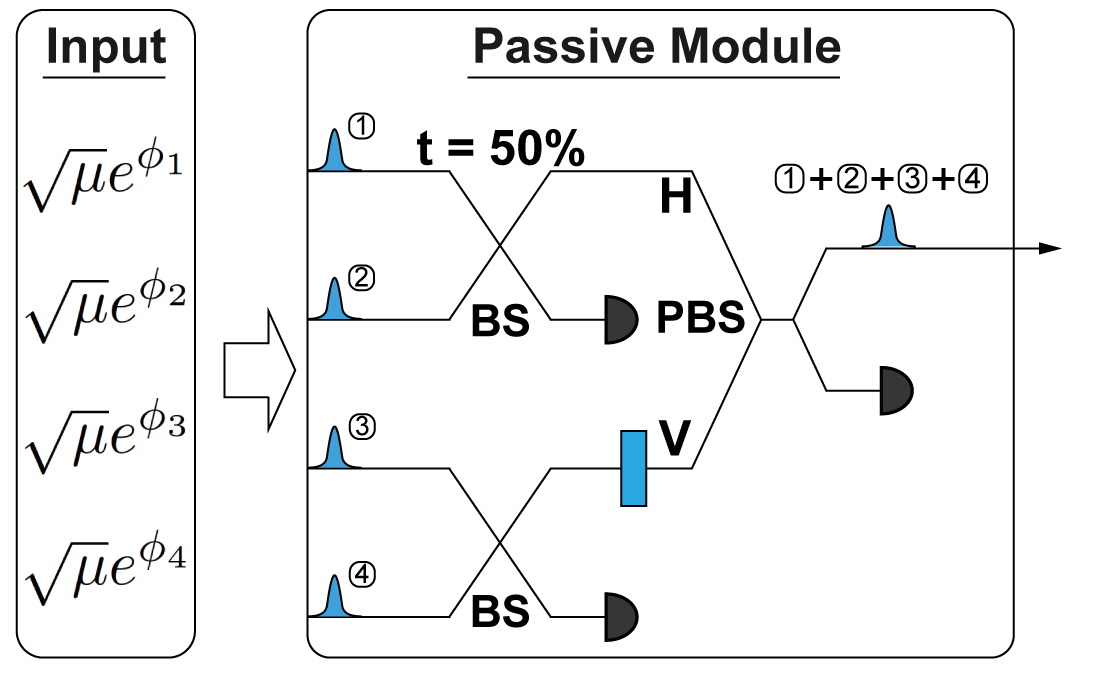
Fully passive modulation. As illustrated in Fig. 1, our fully passive modulation module takes four coherent states with identical intensities and random phases as inputs to produce any polarization state on the Bloch sphere with a random intensity between 0 and the maximum value. Generally, we can write the four strong inputs as {,,,} and the whole process can be described as follows:
(1) Passive decoy state generation. We divide the four input states of strong light into two groups and inject them into 50:50 beamsplitters for interference. Taking one of the groups as an example, we choose one of the interference outputs for local measurement and keep it for local measurement, while the other output serves as the H (V) polarization component that will be used for the next step. The intensities of the two polarization components can be expressed as , in which , . Notice that the phase here are independent random values uniformly distributed in , the obtained intensities of H(V) components follow a U-shaped distribution, whose probability density function is expressed as . Then a post-selection strategy will be used to reshape the intensity distribution to , where is a constant.
(2) Passive polarization encoding. We obtain the final polarization-encoded state by combining the H and V components from the previous step through a polarization beam splitter. We also need to use a beamsplitter to split a portion of the strong light for local measurement. The obtained polarization state can be described by:
| (1) |
where and . It is not difficult to see from equation (1) that for any above-given states , the output state corresponds to a point on the Bloch sphere that can be uniquely determined by the polar angle and azimuthal angle . Actually, it has been proved that any point on the Bloch sphere can also be generated from a set of input states ,Wang et al. (2022a) thus establishing a one-to-one mapping between the input set and output states.
Experimental setup. As illustrated in Fig. 2, an experimental setup with a single laser source is designed for a proof-of-principle demonstration of a fully passive QKD protocol. On the Alice side, in order to generate the initial coherent states with random phases, we utilize a laser diode modeled EP1550-0-NLW and operate it in gain-switch mode. In this mode, by controlling the driving current, the diode emits a pulsed laser with random phases seeded from spontaneous emission. By implementing closed-loop temperature control and precisely setting the driving current, we set the laser’s central wavelength at 1547.38nm. Using the periodic driving signals generated by an arbitrary waveform generator (AWG, Keysight-M8195), we obtained laser pulses with a repetition rate of 20MHz, an average power of 0.1mW, and an effective pulse width of 2ns. Then, we use an erbium-doped fiber amplifier (EDFA) to boost the laser power to about 15mW, ensuring that high-precision local measurements can still be conducted even after the losses incurred by various devices.
The amplified pulses pass through a circulator and enter an asymmetric Michelson interferometer (MZI), composed of a balanced beam splitter and Faraday mirrors (FM). The delay between the two arms of the MZI is set to be precisely equal to one pulse period (50ns), allowing for interference between consecutive pulses. One output from the interference proceeds to subsequent processing, while the other output is directed back through the circulator and detected by a photodetector (PD1) for local measurement, which corresponds to the projection measurement onto the Z basis on the Bob side.
Then, we use a combination of a polarization controller and a polarizer to purify the polarization of the signal light. Subsequently, the pulses enter a polarization-maintaining beam splitter and are equally divided into two paths. We add a 100ns fiber delay to one of the paths, which is precisely equal to two pulse periods. Then, we perform polarization synthesis for each pulse with its next-to-nearest neighboring pulse using a polarization combiner. The resulting polarized pulses are split into two paths by a beam splitter. Most of the power is used for local polarization measurements that correspond to the projection measurement onto the X basis on the Bob side, while a small portion is further attenuated by the variable optical attenuator (VOA). The VOA is precisely set to ensure that the maximum intensity of the WCP of H (V) polarization is about 0.5 photons per pulse before entering the quantum channel.
For the local measurement, we use commercial InGaAs-biased photodetectors with a bandwidth of 5GHz and a rising time of 70ps. And a high-speed data acquisition card (modeled ADQ32) with the highest sampling rate of 5GSa/s and 12-bit resolution is used here to record all the local measurement results. On the Bob side, a standard BB84 decoding module is constructed using a beamsplitter and two sets of polarization measurements that implement projection onto Z and X bases. Four single photon detectors ( Qube series from IDQ) are used here, of which the average efficiency is 10% and the average dark count rate is 500Hz in free running mode. We also use a time tagger device modeled ID900 to collect all the single photon events for post-processing. We use an optical attenuator instead of a real single-mode fiber spool to serve as the quantum channel for a proof-of-principle demonstration (see supplementary materials part I for more experimental details ).
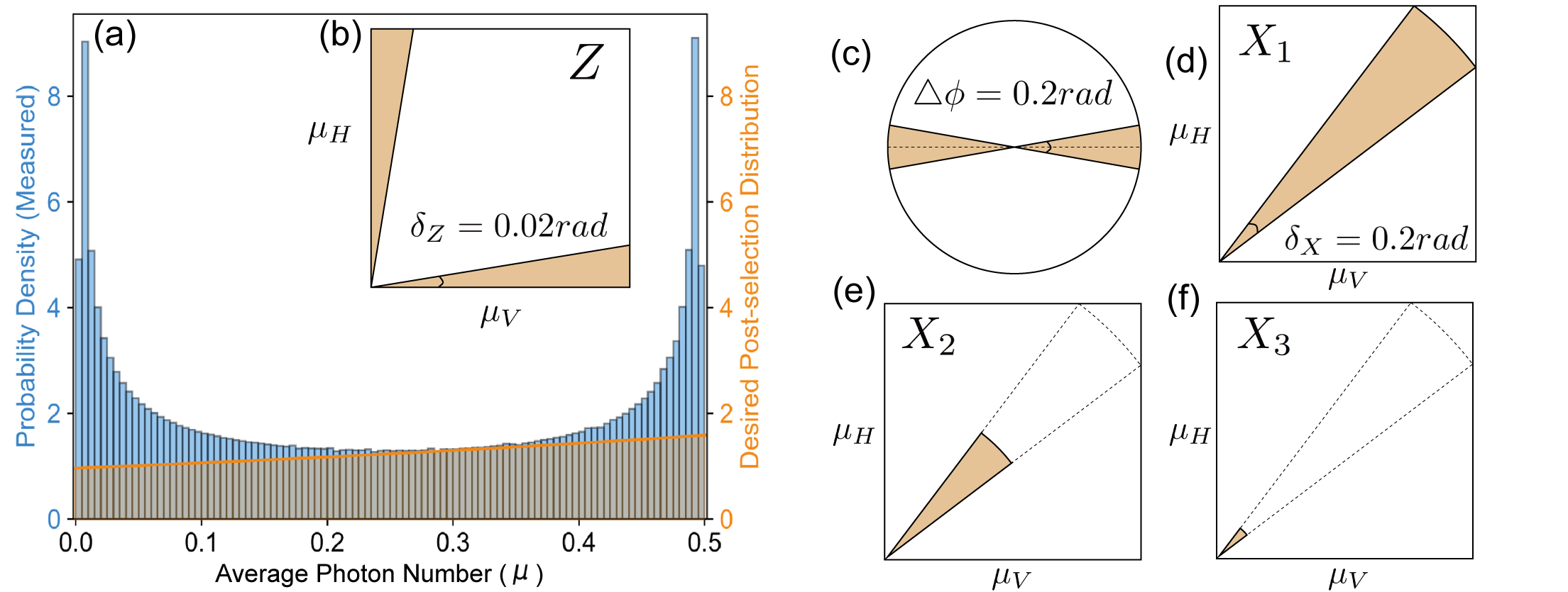
Experimental results. We characterize the gain-switch light source using the data detected by PD1 (in Fig. 2). And these data are also used as the local measurement for the Z basis, recording all the intensity information of H(V) components denoted by (). As shown in Fig. 3(a), the histogram shows the statistical analysis of the output intensities of pulses (re-scaled to the range of [ 0, 0.5 ]), revealing a U-shaped distribution, which indicates that the pulse phases are random values uniformly distributed between 0 and Yuan et al. (2014). In order to decouple the distribution of polarization from intensities in decoy-state analysis, we need to randomly discard some of the pulses according to a specific strategy to obtain our desired distribution (as shown in the shaded area of Fig. 3(a), see supplementary materials part II for details).
| 7.2dB | 11.6dB | 16.7dB | |
|---|---|---|---|
In this work, we only use the Z-basis data for key generation. Unlike the active QKD, we use a region near the poles of the Bloch sphere that can be defined by to determine the Z basis, denoted by the colored region in Fig. 3(b). We set the tolerance to be , where can be calculated using . The determination of the X basis is slightly more complex. First, we need to use to filter out pulses located near the equator of the Bloch sphere, which can be denoted by the colored region in Fig. 3(d). The tolerance is set to be , which can be calculate using . Based on that, we further filter out pulses within a specific azimuthal angle range as shown in Fig. 3(c), to obtain the diagonal (antidiagonal) polarization states D(A). To do that, we need to combine all the local measurement results. We denote the measurement results of PD2 as and calculate the azimuthal angle by:
| (2) |
where can be calculated with . As shown in Fig. 3(c), we define the region () as D (A) states.
It is worth noting that in Fig. 3(d), the selected region is a sector rather than a quadrilateral that includes the top-right corner, which is for the convenience of decoy-state analysis (see supplementary materials part III). We represent this region as X1. Similarly, we represent the other two sector-shaped subregions of X1 as X2 and X3 (shown in Fig. 3(e)(f)), with their radii being 0.5 and 0.1 of X1, respectively. By utilizing these three different intensity sets, we then are able to do the decoy-state analysisMa et al. (2005); Hwang (2003); Wang (2005).
We conduct QKD experiments at three different channel losses: 7.2dB, 11.6dB, and 16.7dB. For each loss situation, we collect data for 1000s with a total data size of . Table. 1 lists the error rate and gain measured in three different channel losses for Z basis. For the X basis, we analyze data from three different intensity regions {} under each loss scenario. Here, the parameters for a 16.7 dB loss scenario are presented in Table 2 and other parameters can be found in supplementary materials part IV. Based on these measured results, we calculate the final key rate using the following formulaWang et al. (2022a):
| (3) | |||
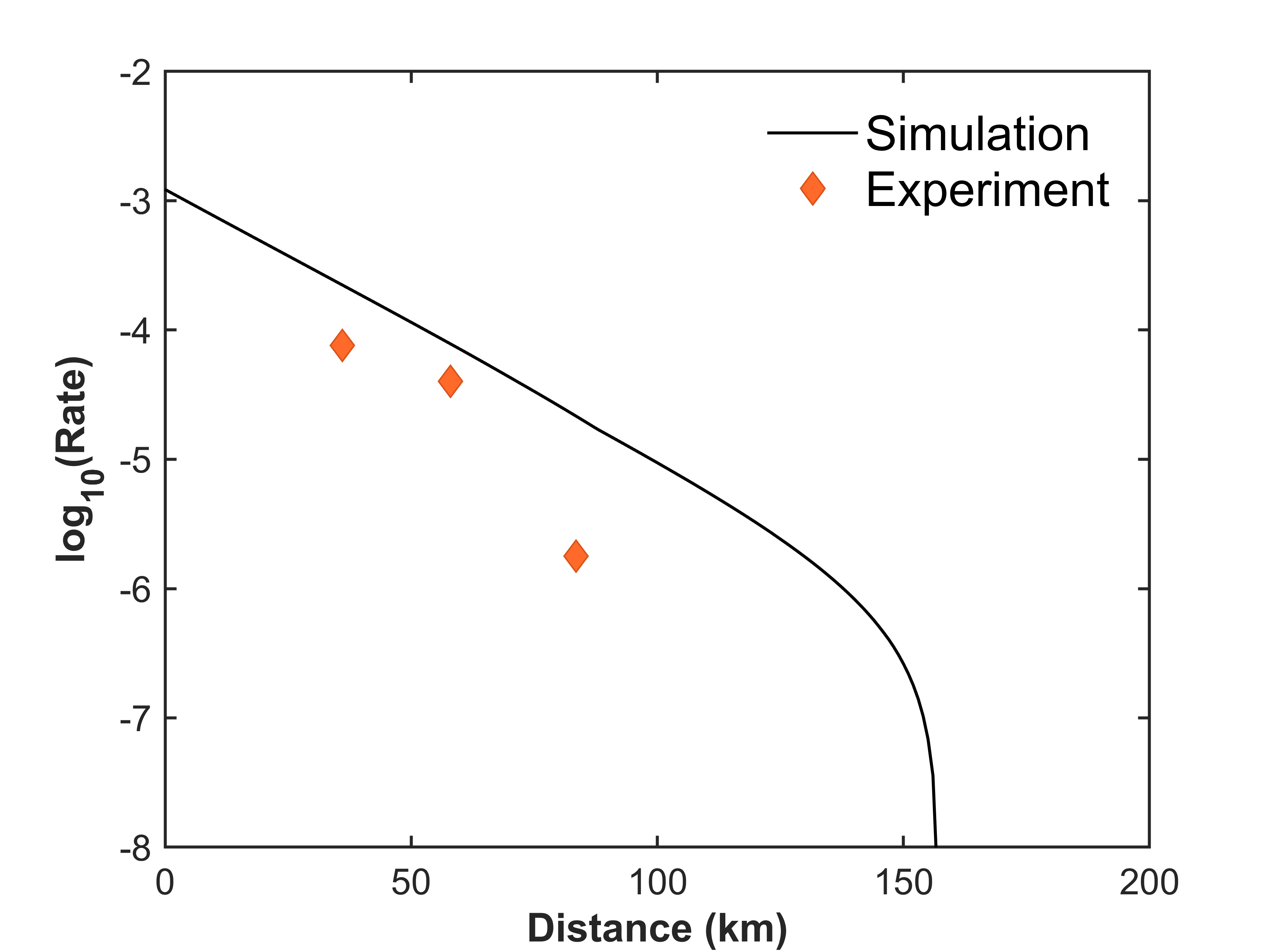
where is the binary entropy function. As plotted in Fig. 4, the obtained final key rate are in 7.2dB, in 11.6dB and in 16.7dB in the asymptotic regime.


Discussion In summary, we successfully demonstrated fully passive quantum key distribution using a single laser source with polarization encoding, under different channel losses, which completely eliminates the side channels introduced by active modulation.
Compared to multi-laser schemes, using a single laser can avoid wavelength side channels and prevent the decrease in interference visibility caused by frequency deviationsMoschandreou et al. (2018); Yin et al. (2016). However, since we use interference between early-late pulse pairs, the output WCPs sequence will not be completely independent of each other. In our protocol, only the first pulse out of every four can be used as a quantum signal, while the remaining three need to be discarded (as a proof-of-principle demonstration, we discard these pulses through post-selection). One solution to this would be adding extra intensity modulators or optical switches to pick the valid pulse. Notice that those modulators or optical switches are only used to periodically switch the signal on and off, without involving any modulation information, so it does not generate side channels.
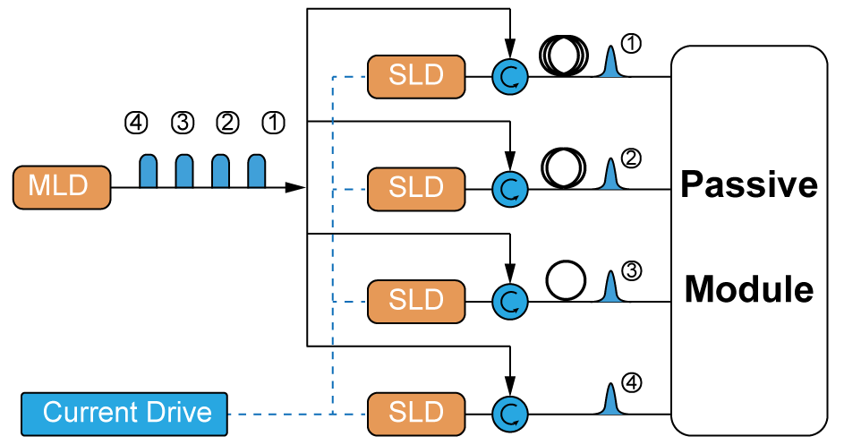
Here, we present a more elegant proposal: one can combine injection locking techniques and fully passive modulation to achieve a completely modulator-free schemeLo et al. (2023). As illustrated in Fig. 5, the master laser generates phase-randomized pulses in gain-switch mode, grouping these pulses in sets of four. By applying driving currents at appropriate timings, the four slave lasers are each seeded by one of the four pulses, thus inheriting their respective phase information. After a suitable delay, the pulses generated by the slave lasers are injected into a fully passive modulation system, thereby resolving the issue of non-independence between adjacent pulses.
Acknowledgements.
Acknowledgments. We thank Li Qian, Zhiliang Yuan, Gai Zhou, Xiong Wu, Rong Wang, and Chenyang Li for their helpful discussions. The project is supported by the University of Hong Kong start-up grant. W. Wang acknowledges support from the Hong Kong RGC General Research Fund (GRF) and the University of Hong Kong Seed Fund for Basic Research for New Staff. H.K. Lo is also supported by NSERC, MITACS, and Innovative Solutions Canada.Note added. Recently, we become aware of a related workLu et al. (2023).
References
- Wang et al. (2022a) W. Wang, R. Wang, C.-Q. Hu,V. Zapatero, L. Qian, B. Qi, M. Curty, and H.-K. Lo, arXiv:2207.05916 (Accepted by Physical Review Letters for publication) (2022a).
- Zapatero et al. (2023) V. Zapatero, W. Wang, and M. Curty, Quantum Science and Technology 8, 025014 (2023).
- Ch and Brassard (1984) H. B. Ch and G. Brassard, in Conf. on Computers, Systems and Signal Processing (Bangalore, India, Vol. 175 (1984).
- Ekert (1991) A. K. Ekert, Physical Review Letters 67, 661 (1991).
- Lo et al. (2012) H.-K. Lo, M. Curty, and B. Qi, Physical Review Letters 108, 130503 (2012).
- Liu et al. (2019) H. Liu, W. Wang, K. Wei, X.-T. Fang, L. Li, N.-L. Liu, H. Liang, S.-J. Zhang, W. Zhang, H. Li, et al., Physical Review Letters 122, 160501 (2019).
- Cao et al. (2020) Y. Cao, Y.-H. Li, K.-X. Yang, Y.-F. Jiang, S.-L. Li, X.-L. Hu, M. Abulizi, C.-L. Li, W. Zhang, Q.-C. Sun, et al., Physical Review Letters 125, 260503 (2020).
- Lucamarini et al. (2018) M. Lucamarini, Z.-L. Yuan, J.-F. Dynes, and A.-J. Shields, Nature 557, 400 (2018).
- Wang et al. (2022b) S. Wang, Z.-Q. Yin, D.-Y. He, W. Chen, R.-Q. Wang, P. Ye, Y. Zhou, G.-J. Fan-Yuan, F.-X. Wang, W. Chen, et al., Nature Photonics 16, 154 (2022b).
- Liu et al. (2023) Y. Liu, W.-J. Zhang, C. Jiang, J.-P. Chen, C. Zhang, W.-X. Pan, D. Ma, H. Dong, J.-M. Xiong, C.-J. Zhang, et al., arXiv preprint arXiv:2303.15795 (2023).
- Zhou et al. (2023) L. Zhou, J. Lin, Y. Jing, and Z. Yuan, Nature Communications 14, 1 (2023).
- Lütkenhaus and Jahma (2002) N. Lütkenhaus and M. Jahma, New Journal of Physics 4, 44 (2002).
- Pang et al. (2020) X.-L. Pang, A.-L. Yang, C.-N. Zhang, J.-P. Dou, H. Li, J. Gao, and X.-M. Jin, Physical Review Applied 13, 034008 (2020).
- Gisin et al. (2006) N. Gisin, S. Fasel, B. Kraus, H. Zbinden, and G. Ribordy, Physical Review A 73, 022320 (2006).
- Tamaki et al. (2016) K. Tamaki, M. Curty, and M. Lucamarini, New Journal of Physics 18, 065008 (2016).
- Bourassa et al. (2022) J. E. Bourassa, A. Gnanapandithan, L. Qian, and H.-K. Lo, Physical Review A 106, 062618 (2022).
- Yoshino et al. (2018) K.-i. Yoshino, M. Fujiwara, K. Nakata, T. Sumiya, T. Sasaki, M. Takeoka, M. Sasaki, A. Tajima, M. Koashi, and A. Tomita, npj Quantum Information 4, 8 (2018).
- Huang et al. (2019) A. Huang, Á. Navarrete, S.-H. Sun, P. Chaiwongkhot, M. Curty, and V. Makarov, Physical Review Applied 12, 064043 (2019).
- Tang et al. (2013) Y.-L. Tang, H.-L. Yin, X. Ma, C. H. F. Fung, Y. Liu, H.-L. Yong, T.-Y. Chen, C.-Z. Peng, Z.-B. Chen, and J.-W. Pan, Physical Review A 88, 022308 (2013).
- Roberts et al. (2018) G. Roberts, M. Pittaluga, M. Minder, M. Lucamarini, J. Dynes, Z. Yuan, and A. Shields, Optics Letters 43, 5110 (2018).
- Lu et al. (2021) F.-Y. Lu, X. Lin, S. Wang, G.-J. Fan-Yuan, P. Ye, R. Wang, Z.-Q. Yin, D.-Y. He, W. Chen, G.-C. Guo, et al., npj Quantum Information 7, 75 (2021).
- Paraïso et al. (2019) T. K. Paraïso, I. De Marco, T. Roger, D. G. Marangon, J. F. Dynes, M. Lucamarini, Z. Yuan, and A. J. Shields, npj Quantum Information 5, 42 (2019).
- Woodward et al. (2021) R. I. Woodward, Y. Lo, M. Pittaluga, M. Minder, T. Paraïso, M. Lucamarini, Z. Yuan, and A. Shields, npj Quantum Information 7, 58 (2021).
- Curty et al. (2009) M. Curty, T. Moroder, X. Ma, and N. Lütkenhaus, Optics Letters 34, 3238 (2009).
- Curty et al. (2010) M. Curty, X. Ma, B. Qi, and T. Moroder, Physical Review A 81, 022310 (2010).
- Sun et al. (2014) Q.-C. Sun, W.-L. Wang, Y. Liu, F. Zhou, J. S. Pelc, M. Fejer, C.-Z. Peng, X. Chen, X. Ma, Q. Zhang, et al., Laser Physics Letters 11, 085202 (2014).
- Sun et al. (2016) S.-H. Sun, G.-Z. Tang, C.-Y. Li, and L.-M. Liang, Physical Review A 94, 032324 (2016).
- Zhang et al. (2012) Y. Zhang, S. Wang, Z.-Q. Yin, W. Chen, W.-Y. Liang, H.-W. Li, G.-C. Guo, and Z.-F. Han, Chinese Physics B 21, 100307 (2012).
- Li et al. (2022) C. Li, C. Hu, W. Wang, R. Wang, and H.-K. Lo, arXiv preprint arXiv:2212.01876 (2022).
- Comandar et al. (2016) L. Comandar, M. Lucamarini, B. Fröhlich, J. Dynes, A. Sharpe, S.-B. Tam, Z. Yuan, R. Penty, and A. Shields, Nature Photonics 10, 312 (2016).
- Yuan et al. (2016) Z. L. Yuan, B. Fröhlich, M. Lucamarini, G. L. Roberts, J. F. Dynes, and A. J. Shields, Physical Review X 6, 031044 (2016).
- Yuan et al. (2014) Z. Yuan, M. Lucamarini, J. Dynes, B. Fröhlich, A. Plews, and A. Shields, Applied Physics Letters 104, 261112 (2014).
- Ma et al. (2005) X. Ma, B. Qi, Y. Zhao, and H.-K. Lo, Physical Review A 72, 012326 (2005).
- Hwang (2003) W.-Y. Hwang, Physical Review Letters 91, 057901 (2003).
- Wang (2005) X.-B. Wang, Physical Review Letters 94, 230503 (2005).
- Moschandreou et al. (2018) E. Moschandreou, J. I. Garcia, B. J. Rollick, B. Qi, R. Pooser, and G. Siopsis, Journal of Lightwave Technology 36, 3752 (2018).
- Yin et al. (2016) H.-L. Yin, T.-Y. Chen, Z.-W. Yu, H. Liu, L.-X. You, Y.-H. Zhou, S.-J. Chen, Y. Mao, M.-Q. Huang, W.-J. Zhang, et al., Physical Review Letters 117, 190501 (2016).
- Lo et al. (2023) Y. Lo, R. Woodward, N. Walk, M. Lucamarini, I. De Marco, T. Paraïso, M. Pittaluga, T. Roger, M. Sanzaro, Z. Yuan, et al., APL Photonics 8, 036111 (2023).
- Lu et al. (2023) F.-Y. Lu, Z.-H. Wang, J.-L. Chen, S. Wang, Z.-Q. Yin, D.-Y. He, R. Wang, W. Chen, G.-J. Fan-Yuan, G.-C. Guo, et al., arXiv preprint arXiv:2304.11655 (2023).