NDEx-100 Conceptual Design Report
Abstract
Observing nuclear neutrinoless double beta (0) decay would be a revolutionary result in particle physics. Observing such a decay would prove that the neutrinos are their own antiparticles, help to study the absolute mass of neutrinos, explore the origin of their mass, and may explain the matter-antimatter asymmetry in our universe by lepton number violation.
We propose developing a time projection chamber (TPC) using high-pressure 82SeF6 gas and top-metal silicon sensors for read-out in the China Jinping Underground Laboratory (CJPL) to search for neutrinoless double beta decay of 82Se, called the NDEx experiment. Besides being located at CJPL with the world’s thickest rock shielding, NDEx combines the advantages of the high (2.996 MeV) of 82Se and the TPC’s ability to distinguish signal and background events using their different topological characteristics. This makes NDEx unique, with great potential for low-background and high-sensitivity 0 searches.
NDEx-100, a NDEx experiment phase with 100 kg of SeF6 gas, is being built, with plans to complete installation at CJPL by 2025. This report introduces 0 physics, the NDEx concept and its advantages, and the schematic design of NDEx-100, its subsystems, and background and sensitivity estimation.
NDEx-100 collaboration
I The Physics
The Standard Model (SM) of particle physics is an important cornerstone of physics and the entire natural sciences that has successfully undergone experimental testing for more than half a century. The discovery of its last component, the Higgs particle, marked the perfect end of an era. In the SM, neutrinos have no mass. However, their oscillations, which have been observed nowadays by many independent experiments and are supported by irrefutable evidence, require the presence of a non-diagonal mass term in the flavor basis. This is the first experimental proof of physics beyond the SM in particle physics. Some properties of neutrinos remain unknown, such as whether they are Dirac or Majorana fermions, their absolute mass, and their mass hierarchy.
The charged fermions in the SM are all Dirac particles, which gain mass through Yukawa coupling with the Higgs boson. Because neutrinos are electrically neutral, they are the only candidates in the SM to be Majorana fermions, i.e. they could be their own antiparticles. If this is the case, we can also explain why their masses are significantly lower than those of other charged leptons in the SM by introducing a seesaw mechanism Mohapatra and Senjanovic (1980). Neutrinoless double beta decay experiments are the ideal way to determine if this is the case; if such a process is observed, it would be irrefutable proof that neutrinos are Majorana particles, opening the door to new physics. The measured decay rate can quantitatively constrain the absolute mass and mass ordering of neutrinos. Additionally, neutrinoless double beta decay violates lepton number and CP parity conservations, which can generate a net lepton number in the early universe evolution, thus explaining the matter-antimatter asymmetry in the universe.
II NDEx Concept and its Advantages
The rate of neutrinoless double beta (0) decay occurrence (if it occurs) is extremely low, making experimental observations difficult. These experiments have been developed for decades, with intense competition among the various experimental approaches. Existing large-scale experiments include GERDA Agostini et al. (2020), MAJORANA Aalseth et al. (2018), CUORE Adams et al. (2022), CUPID Augier et al. (2022), KamLAND-Zen Abe et al. (2023), and EXO Anton et al. (2019). In China, experiments including CDEX Wang et al. (2017), PandaX Ni et al. (2019), CUPID-China Xue et al. (2017), and JUNO Zhao et al. (2017) have searched for or are being developed to search for 0 decay. Currently, the highest experimental half-life sensitivity reaches years, yet no such decay has been observed. Next-generation 0 decay experiments are approaching the sensitivity needed for the inverted hierarchy of neutrino masses, on the order of years for most 0 decay isotopes. For the normal hierarchy of neutrino masses, which is slightly favored by oscillation experiment results, the required experimental half-life sensitivity is two orders of magnitude higher, on the order of about years.
Reducing the experimental background is key to improving the sensitivity of neutrinoless double beta decay experiments. With zero background, the experiment’s sensitivity is proportional to the exposure (mass of decay isotope experiment time). However, with a high background, the experimental sensitivity increases with the square root of exposureGomez-Cadenas et al. (2011). Thus, to increase experimental sensitivity by another 1-3 orders of magnitude, innovative techniques must be applied to significantly reduce the experimental background.
The concept of a “No neutrino Double-beta-decay Experiment (NDEx)”, searching for the neutrinoless double beta decay of 82Se using a high-pressure gas time projection chamber (TPC) with 82SeF6 as the working medium and read out by Topmetal sensor chips, was proposed by D.R. Nygren, B.J.P. Jones, N. López-March, Y. Mei, F. Psihas and J. Renner in 2018 Nygren et al. (2018). This scheme combines the high of 82Se with the ability of TPC to distinguish between the signal and background using event topology, which can significantly reduce the experimental background. The of 82Se is as high as 2.996 MeV, which is higher than most natural radioactive backgrounds and that of the decay isotopes currently used in many mainstream experiments. For example, the natural radioactive background near the of 82Se is more than two orders of magnitude lower than that around the of (2.458 MeV). Meanwhile, in gaseous TPC, the double beta decay can be reconstructed as two electron tracks, each with a distinct Bragg peak at the end. This feature can be used to distinguish the signal from the background.
However, this experimental concept faces a major technical challenge: SeF6 is an electronegative gas, in which the electrons generated by ionization quickly combine with gas molecules to form negative ions, and electron avalanche amplification cannot happen. Thus, the weak signals cannot be read out with traditional technologies. To solve this problem, we designed the Topmetal-S sensorGao et al. (2019); You et al. (2021), a kind of silicon sensor chip with a layer of metal on top, dedicated to 0 decay experiments, making TPC without physical amplification possible. It adopts an industrial semiconductor CMOS process, and the top layer has a metal sheet for charge collection. In principle, its noise level can be as low as about 30 e-; thus, the primary ionized charge can be directly read out without physical amplification, providing a unique opportunity to search for 0 decay using the 82SeF6 gas TPC.
The construction of the China Jinping Underground Laboratory (CJPL) provides a unique opportunity for developing 0 decay experiments. CJPL has the thickest natural rock shield in the world, and the second phase of CJPL is being constructed with a world-class experimental space and a low background environment. NDEx will be developed at CJPL, taking full advantage of its low background level and large space.
III NDEx-100 Schematic Design
III.1 NDEx-100 Overall Design
This study develops a NDEx-100 experiment with 100kg of natural SeF6 gas. The preliminary design is shown in Fig. 1. The main body of the experiment is in a pressure chamber, with feed-through flanges for gas, low-voltage, optical fibers, and high-voltage. An inner copper shielding inside the pressure chamber shields most of the external radiation. The core detector of the experiment - TPC - is installed in the barrel part of the chamber, comprising an insulating layer, a high-voltage plane, a field cage, and a readout plane. The readout plane consists of the focusing layer and the readout electronics layer on which the Topmetal-S sensor chips are mounted. In addition to the main body of the experiment, there are lead and high-density polyethylene (HDPE) external shieldings surrounding the pressure chamber, as well as auxiliary facilities such as the gas system, which are not shown in Fig. 1.
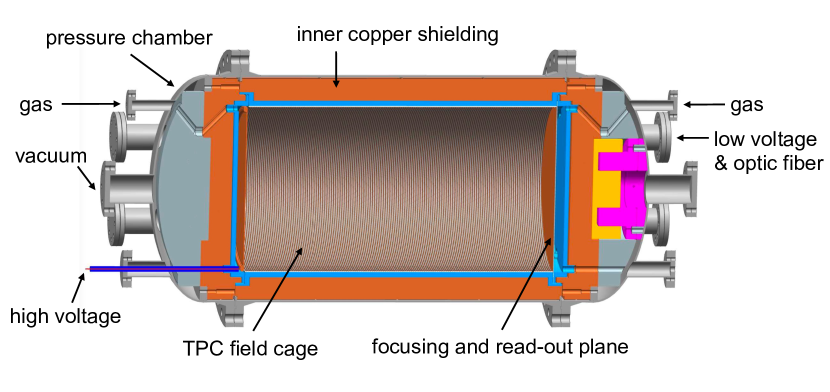
During the experiment, 82Se (with a natural abundance of 8.7%) in SeF6 gas undergoes double beta decay, releasing two electrons. The total energy of the two electrons is 2.996 MeV for the neutrinoless double beta decay. These two electrons lose energy in the gas, ionize the gas, and form curved tracks due to scattering. At the ends of the two tracks, two Bragg peaks with the largest energy loss are formed. Due to the electronegativity of SeF6, the electrons generated by ionization quickly form negative ions with surrounding SeF6 molecules. Finally, various SeF ions are formed in certain fractions, including SeF and SeF, which drift to the two ends of the TPC in the electric field. After the SeF ions reach the readout plane, their signals are read out. The drift velocities of SeF and SeF ions are different, as are their arrival times. This time difference can be used to obtain the drift distance. The readout plane comprises the focusing and readout electronics layers; the focusing layer generates a certain electric field structure with small holes that allow the passage and collection of drift charges with 100% efficiency at the 1 mm2-sized readout electrodes on the surface of the Topmetal-S chips. The Topmetal-S chips, located on the surface of the readout electronics layer, measure the charge and time of the signal and generate digital data, which are collected by the electronic readout boards and transmitted to the data acquisition computer through the optical fibers.
III.2 Pressure Chamber and Inner Copper Shielding
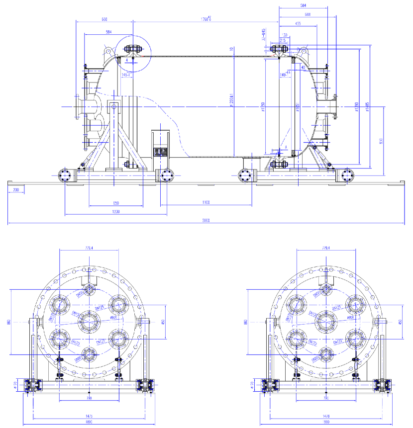
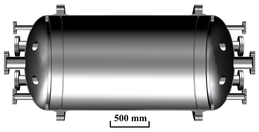
NDEx-100 uses the SeF6 gas at a pressure of 1.0 MPa. This pressure is chosen to obtain more SeF6 gas mass within a certain volume while avoiding liquefication Nygren et al. (2018). The pressure chamber design is shown in Fig. 2. The chamber comprises a barrel and two end caps, connected with two DN1200 Tongue-Grove (T-G) flanges. There are seven smaller T-G flanges on each end cap: one DN50 flange for gas, one DN80 flange for high voltage, four DN125 flanges for low-voltage and optic fibers, and one DN150 flange for vacuum. The inner diameter and length of the barrel are 1200 mm and 1760 mm, respectively. The chamber is made of 10 mm-thick, low background, stainless steel. Figure 3 shows the cross-sectional view of the chamber. The weight of the chamber is around 2211 kg without considering the bolts. The barrel part of the pressure chamber sits on two saddles, while the two end caps are supported with carts, which can move away along the rails when opening the chamber.
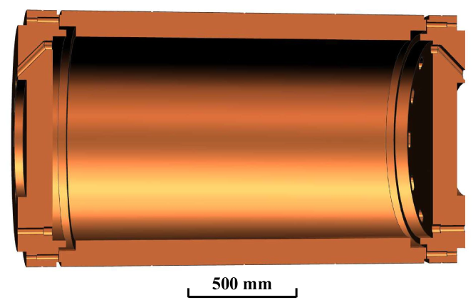
A 12 cm-thick oxygen-free copper shielding with low radioactive isotope contamination is placed inside the pressure chamber to suppress the background radiation from the pressure chamber and outside, as shown in Fig. 1. Figure 4 shows a cross-sectional view of the inner copper shielding design, comprising a barrel part and two disks mounted in the end cups of the pressure chamber. The outer and inner diameters of the barrel part are 1190 mm and 950 mm, respectively. The barrel part and the disks weigh about 6108 kg and 1476 kg, respectively. The disks have some holes enabling the passage of gas, optic fibers, low-voltage cables, and the high-voltage feedthrough. The holes, except the ones for high voltage, are tilted to avoid outside radiation reaching the sensitive volume of the TPC via a straight path.
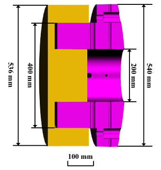
The Topmetal sensors and electronics on the readout plane will generate heat when taking data, which will induce convection in the SeF6 gas in the sensitive volume, with a maximum velocity larger than 10 cm/s assuming heat power of 700 W on the readout plane. This could be a problem for NDEx TPC because the ions drift very slowly, with a velocity above 20 cm/s, which is significantly lower than the drift velocity of electrons (on the order of several cm/s in most other TPC’s), and the convection could cause serious distortion of the reconstructed event topology. Thus, cooling the readout plane and minimizing the temperature non-uniformity inside the TPC is necessary. For this purpose, a copper heat conductor will be placed between the inner copper shielding disk and the end cap of the pressure vessel. As shown in Fig. 1, the heat conductor is composed of a base (in yellow) and a tube (in purple) fixed to the inner copper shielding disk and to the pressure chamber end cap, respectively. Figure 5 shows the cross-sectional view of the copper heat conductor with dimensions. The base and the tube can slide horizontally relative to each other. This design ensures good contact between all neighboring parts along the heat conduction path, even when the pressure chamber expands due to the gas pressure, so that the total heat resistance is acceptable. The weight of the copper heat conductor is around 489 kg. A liquid cooling plate will be mounted on the outer surface of the end cup of the pressure chamber. The temperature difference in the TPC and convection in the gas will be minimized by adjusting the temperature of the cooling plate.
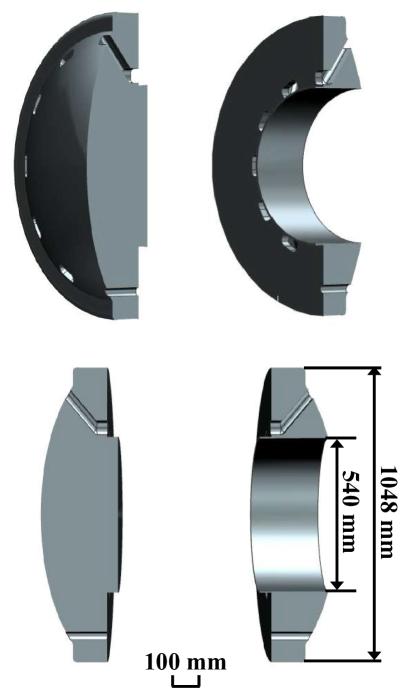
The SeF6 and 82SeF6 gases are very expensive. Two plastic fillers will be placed in the end caps of the pressure chamber to reduce the amount of the gas to be used, occupying the gap outside the inner copper shielding disks, as shown in Fig. 1. Since SeF6 is toxic, any material that absorbs the gas and gradually releases it when the pressure chamber is open during the maintenance of the experiment could endanger people and the environment. Considering this, the fillers, as well as the insulator layer and the TPC field cage supporting cylinder to be described in the next subsection, will be made of polyoxymethylene (POM), which absorbs the minimum amount of gas among plastic materials with acceptable mechanical strength. The design of the fillers is shown in Fig. 6. There are also some holes in the fillers for gas, optic fibers, low voltage cables, and the high voltage feedthrough to go through.
The pressure chamber and the inner copper shielding have been manufactured for an above-ground prototype experiment. The copper heat conductor and the fillers are being manufactured. The above-ground prototype will be assembled in the near future. Then, tests of the gas tightness of the pressure chamber, heat conduction, and temperature control of the readout plane will be conducted.
III.3 Field Cage
The electronegativity of the SeF6 gas used in NDEx-100 is very high. This means the negatively charged particles drifting towards the readout plane will not be electrons since they are quickly captured, but negative ions instead. The readout plane will employ innovative Topmetal-S sensors to read out the drifted charge without physical amplification like an electron avalanche. Details about Topmetal-S sensors and the readout plane will be introduced in Sub-section III.4.
Most of the drift negative ions will be SeF and SeF; however many more complex molecules may be formed. The drifting negative ions may form clusters like SeF(SeF6)n and SeF(SeF6)n (n=1,2,3,…) with a low drift field. These clusters will smear the drift velocity of the negative ions, resulting in increased noise. Similar to SF6, the cluster formation in SeF6 can be suppressed with high drift fields. Consequently, the drift field of NDEx-100 will be as high as 400 V/cm, corresponding to a drift velocity of negative ions above 20 cm/s.
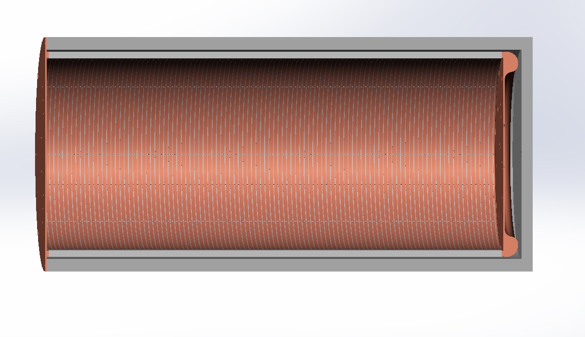
A cross-sectional view of a prototype field cage (FC) design is shown in Fig. 7. The FC is isolated from the inner copper shielding by a 20 mm-thick POM cylinder. The FC will be made of flexible printed circuit (FPC) sheets sized 315 mm423 mm. Each FPC has 5 mm-wide copper strips with a pitch of 6 mm on both sides. Three snap-off holes at both ends and the center of each copper strip will be used to align and fix the FPC sheets onto a 10 mm-thick POM supporting cylinder with screws. Two copper rings will be mounted at the two ends of the POM supporting cylinder. The copper strips and copper rings will be connected using low radioactive background resistors. The cathode of the TPC will be a low radioactive background copper plane mounted on the inner copper shielding disk, isolated with a POM layer of thickness 25 mm. 8 pogopins will be used to ensure a good connection between the cathode plane and the copper ring on the end of the cylinder part of the FC once the pressure chamber is closed.
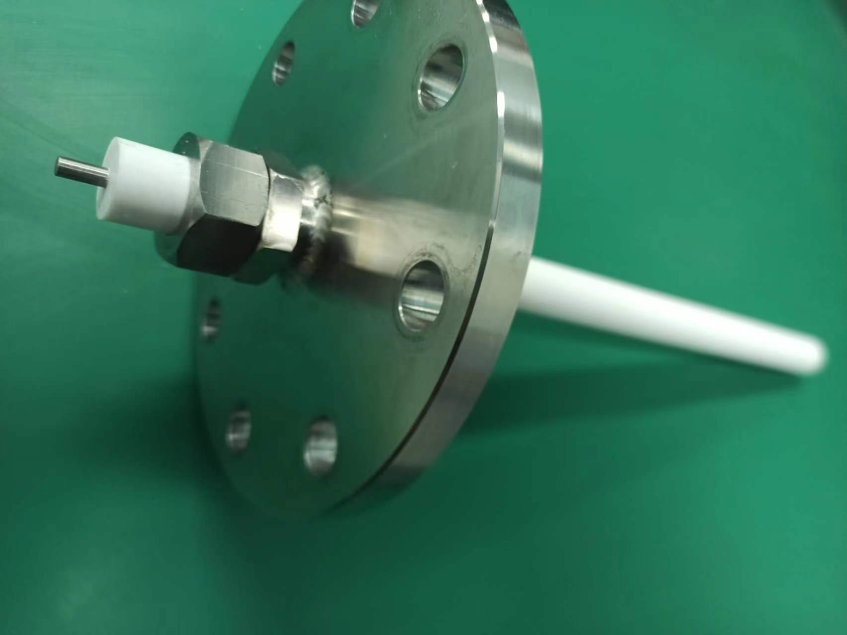
A high-voltage feedthrough will be connected to the cathode by spring pins. It is constructed using a compression seal approach, as shown in Fig. 8. A metal rod is pressed into a Polytetrafluoroethylene (PTEF) seal ring by clamping nuts on a DN80 flange. The feedthrough has been tested with a high voltage of 100 kV and for leak-tightness in nitrogen at 1.0 MPa.
III.4 Topmetal-S Sensor and Readout Plane
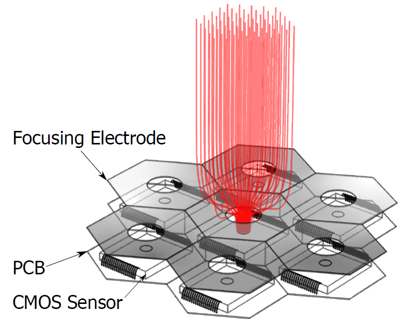
Around 10k CMOS sensors, named Topmetal-S, arranged in a hexagonal pattern as shown in Fig. 9, will be directly placed at the site of charge measurement to collect ionization charges without avalanche multiplication. A perforated focusing electrode is placed above the readout plane with round holes aligned with the charge collection electrodes on the Topmetal-S sensors concentrically. The focusing structure ensures all charges eventually land on the charge collection electrode for maximum charge collection efficiency.
Each Topmetal-S sensor is integrated with a charge collection electrode, a front-end amplifier, and data processing circuits. The charge collection electrode is an exposed hexagonal top-most metal with a diameter of about 1 mm. The charge signal collected on the Topmetal electrode is directly DC coupled to the charge sensitive pre-amplifier (CSA). The structure of the CSA in the prototype Topmetal-S sensor is a folded cascade amplifier with a feedback capacitor and a feedback transistor. The decay time of the CSA can be adjusted by changing the gate voltage of the feedback transistor.
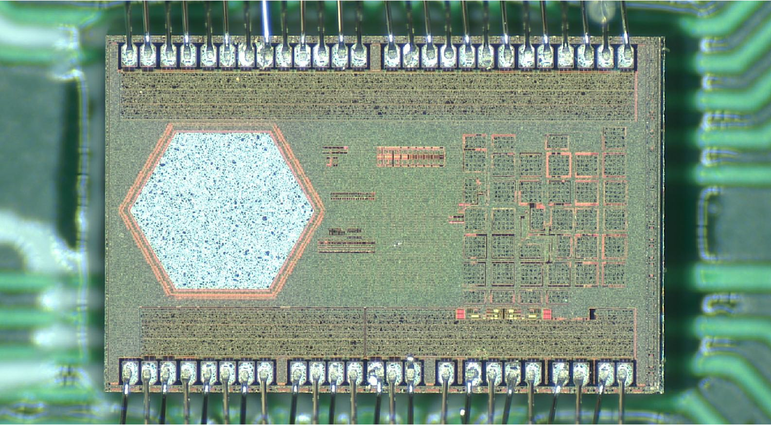
Due to the stringent noise requirement, the analog signal of the CSA output must be digitized immediately. Thus, an in-chip Analog-to-Digital Converter (ADC) is designed to minimize the analog signal transfer. The ADC should have a noise floor well below the noise of the CSA of about 1 mV and a large enough dynamic range to cover the possible input charge range up to about 40 ke-. A sigma-delta (SD) ADC is used in the Topmetal-S sensor. It comprises an SD modulator (analog part) with coarse quantizers and a decimation filter (digital part) together to produce a data-stream output. By sampling the input signal at a frequency significantly higher than the signal bandwidth (oversampling), most of the noise shifts beyond the band of interest. A decimation filter further attenuates the out-of-band noise to achieve an improved signal-to-noise ratio. A photo of the Topmetal-S sensor chip is shown in Fig. 10.
Since the sensors are densely packed on the plane, the number of available paths for the routing signal out of the plane is limited. Beyond a certain plane size or total number of sensors, routing every signal from all sensors out becomes impractical. Digitized data must be communicated through an inter-sensor network. Therefore, the circuitry that handles data processing and communication must be integrated into the sensor. A distributed, self-organizing, and fault-tolerant readout network is proposed with the Topmetal-S sensor. The proposed scheme forms a sensor network by establishing a local connection between the adjacent sensors. Each sensor integrates a router as a network node; hence, each sensor not only generates and transmits its data but also forwards the data from its adjacent nodes. Finally, the data are received by a data acquisition system, which is directly connected to the network edge and used to transmit the data between the sensor network and the computer.
III.5 Data Acquisition
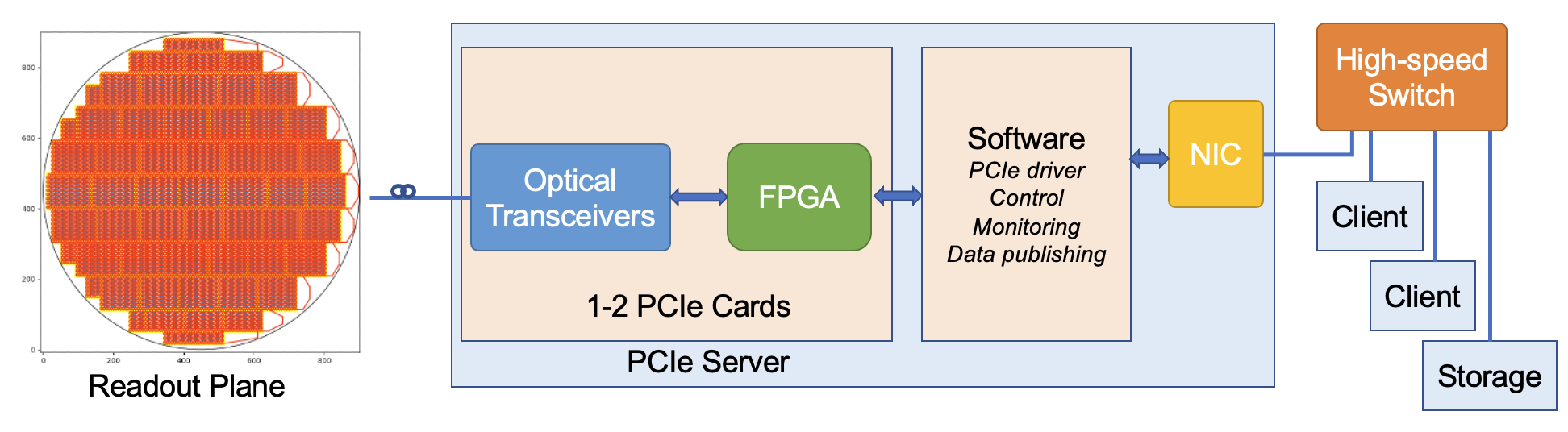
Based on the two-dimensional distributed network formed by the digital part of the Topmetal-S sensors, the digitized waveform of each CSA output will be transmitted to the edge of the plane as the streaming readout. The speed of the data chain could go up to 45 Mbps. As shown in Figure 11, the full plane is split into modules with different sizes to cover the end cap as much as possible. All the streaming data chains end in the modules on the right side, where the data are further encoded and aggregated into high-speed links with a speed of a few Gbps, by the commercial transceiver chips. Depending the on orientation of the sensors and how the sensors on the edge columns are connected to the transceiver, there will be 2050 bidirectional high-speed links in total to connect the readout plane and the DAQ system in the back-end. In the other direction, the control data streams from the DAQ system are transmitted towards the left side of the readout plane.
The flexible Printed Circuit Board (PCB) modules will be fabricated with radiopure material. CMOS chips, such as the Topmetal-S sensors, are known to be low in radioactive contamination. Other components, including the capacitors, resistors, transceivers, and some power chips, will be selected carefully. The radioactivity measurements will be done in the CJPL. Besides the material and components, any tools or materials used during the assembly procedures should also be clean enough.
A PCIe-based DAQ system will be built in the back-end to communicate with the front-end electronics on the readout plane via high-speed fiber optic links. A similar PCIe form factor has been adopted by dozens of large-scale experiments, such as the ATLAS experiment at the LHC and the sPHENIX experiment at the RHIC Anderson et al. (2016); Chen et al. (2020). The streaming data from all sensors are received and decoded by FPGAs on the PCIe cards. The data processing, event building, and filtering can be flexibly placed in the chain from the FPGA firmware to the software. The raw data and kinds of intermediate-stage data will be streamed from the DAQ server to a high-speed switch. Any client connected to the network can remotely subscribe to the data and implement further data analysis.
III.6 External Shielding
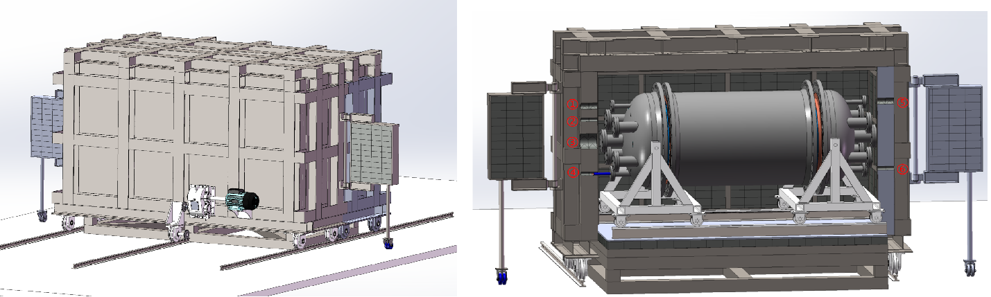
An external lead shielding with a thickness of 20 cm will be built outside the pressure chamber to protect the NvDEx detector from environmental radiation. The preliminary design of the external lead shielding is shown in Fig.12. It comprises two mobile halves and a fixed base on which the pressure chamber sits. The mobile halves, including the side walls and the top, are installed on a mobile base connected to a transmission system so that they can be adjusted to enable opening and operations on the pressure chamber. The fixed base is installed on a vibration isolation system to minimize the influence of vibration on the experimental measurements. The vacuum and gas pipes, high- and low-voltage cables, and the optical fibers will pass the external lead shielding through several holes at the joints of the two mobile halves. Two shielding doors will be installed to prevent radiation from going through these holes directly. The lead bricks and the steel structure inside the lead layer will be selected and tested for radioactive contamination.
Lead is very effective for stopping external radiation; however, it is not a good shielding material for neutrons. High-density polyethylene (HDPE) blocks will be placed as much as possible between the pressure chamber and external lead shielding to slow down and absorb neutrons. The lead shielding exterior will also be covered with a 30 cm-thick layer of HDPE. The HDPE material will also be tested for radioactivity.
III.7 Gas System
The working medium of NDEx is highly toxic SeF6 gas. When there is moisture in it, SeF6 can easily decompose and produce corrosive HF, which may damage detector components and/or cause toxic gas leakage. The gas system of NDEx can fill the pressure chamber with SeF6 to the working pressure of 1 MPa, discharge the gas from the pressure chamber, and safely store it during experimental maintenance. During the lifetime of the experiment, the pressure vessel will be pressurized, depressurized, and vacuumized many times, and the pressure vessel and part of the gas system will operate at a pressure of 1 MPa for years during data collection. Thus, gas tightness and reliability are critical for the NDEx gas system.
With these considerations, the schematic of the NDEx gas system is designed as shown in Fig. 13.
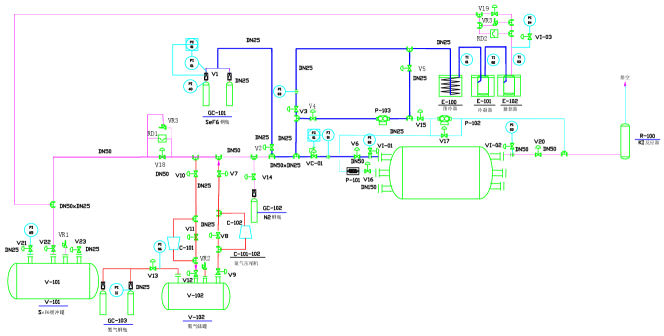
The pressure chamber is connected to a turbomolecular vacuum pump and a dry vacuum pump, which can vacuumize the chamber and the gas system before filling SeF6 gas. This can minimize contamination of the SeF6 gas by air, moisture, and radon to avoid corrosion and radiation background from the gas.
Every time before filling the toxic SeF6 gas to the chamber, SF6, which has similar properties as SeF6 but is non-toxic, is filled into the system with a pressure of 1 MPa to test the gas tightness of the pressure chamber and gas system. After the test, SF6 is compressed into a SF6 storage tank for future use.
In emergencies like gas leakage, fire, an earthquake, a power outage, etc., SeF6 gas in the system will be released into an emergency pressure relief tank within 10 seconds so that the pressure in the system is below atmospheric pressure to ensure personnel and environmental safety.
Before experimental maintenance, SeF6 gas is discharged from the pressure chamber and condensed by the low temperature in a precooler and two condensers. After the SeF6 saturated vapor pressure is reached, a dry vacuum pump pumps the gas from the pressure chamber to the condensers. Then, any trace amount of SeF6 left in the system is flushed by nitrogen gas into a potassium iodide (KI) reactor to be absorbed. The SeF6 is safely stored in the condensers at low a temperature as solid and vapor below atmospheric pressure, which can be refilled in the pressure chamber in the future.
All the components for the gas system have been purchased and are waiting to be assembled once the experimental pressure chamber manufacture is complete. Before moving to CJPL, the system will be commissioned and tested in the above-ground lab with SF6 gas.
III.8 Airtight Clean Room
The entire experimental setup is placed in an airtight clean room to ensure the whole experimental process is safe. Enough potassium iodide (KI) reagent is placed in the airtight clean room as a second line of defense for environmental safety.
The control room is located outside the airtight clean room. Under normal working conditions, the airtight clean room is in an airtight state, and the entire experimental setup, including the gas system, can be controlled remotely. In case of a gas leakage, the gas system releases the SeF6 gas into the pressure relief tank, and the KI reagent placed in the airtight clean room reacts with the leaked SeF6 and absorbs it. The airtight clean room is divided into three areas that are airtightly isolated from each other. The main experimental setup and most gas systems are located in one area. Two SeF6 condensers that serve as backups for each other are placed in the other two areas. When people need to operate the experiment in the main area of the experimental setup, all SeF6 gas should be condensed in one of the condensers first to eliminate SeF6 gas in the main area. Further, the pressure inside the condenser is the vapor pressure of SeF6, which is far below atmospheric pressure, so the leakage of a large amount of gas is impossible. In rare cases where people need to conduct on-site operations on a condenser, SeF6 is first condensed in the other condenser. Therefore, people are always in an airtight clean room without SeF6 gas.
The airtight clean room needs to reach a clean level of 100k to control the background radioactivity by preventing the surface of the detector from being contaminated. The temperature in the airtight clean room needs to be controlled at 222∘C to minimize the gas convection in the TPC. Concurrently, the humidity must be 3010% to avoid moisture condensation at cold spots in the experimental setup, such as the cooling plate on the pressure chamber.
IV Background and Sensitivity Estimation
IV.1 Natural Radioactive Background
Radioactive isotopes are always present in the walls of the hall and in the rock surrounding them, as well as in the materials of the experimental setup. The decay of these isotopes produces a large amount of , , and particles. However, the first two will mostly be stopped without causing a detectable background unless they are generated in or near the sensitive volume. So, we mainly focus on the latter. particles penetrating into the sensitive volume may interact with the gas and generate free electrons visible to the detector, making them a major background source for NDEx.
A 20 cm-thick external lead shielding and a 12 cm-thick inner copper shielding outside and in the pressure chamber shield the external particles. The thicknesses of the shielding layers are optimized using Geant4 simulations Allison et al. (2006); Agostinelli et al. (2003); Allison et al. (2016). Owing to the presence of radioactive contamination in the shielding materials, the flux in the sensitive volume does not always decrease as the shielding thickness increases.
Assuming Topmetal-S sensors can achieve 30 e- noise level, on average, 25 sensors are fired per 0 event, and the ionization energy and Fano factor of SeF6 are equal to that of SF6 (32 eV, 0.19), then the FWHM energy resolution calculated is 0.51%. Considering deviations from the above assumptions and imperfections of the experiment, to be conservative, we assume 1% FWHM energy resolution and use this energy range (2.98-3.01 MeV) as the region of interest (ROI) in the following background estimations.
Most of the ROI background comes from the decay of 214Bi from the 238U decay chain. The probability of having a with energy larger than 2.9 MeV from a 214Bi decay is Brown et al. (2018), which is quite rare. This is the advantage of 82Se’s high for NDEx. 208Tl from the 232Th decay chain contributes about one order of magnitude less ROI background than 214Bi, with only around Brown et al. (2018) of the produced having energy around and above the ROI. Thus, we only focus on the 238U decay chain in our background simulation and estimation.
The 238U radiation activities of materials considered in our simulations are listed in table 1. The 238U activity of the concrete in the experimental hall walls is from a measurement at CJPL Ma et al. (2021). The contribution of the rocks is negligible since the contamination rate of the rocks is significantly lower than that of the concrete. For other materials in the experimental setup, we used the measurements from the NEXT experiment Alvarez et al. (2012). These numbers will be updated using measurements of materials for NDEx in the future. The activity of the POM material used for the TPC field cage is assumed to be identical to that of HDPE in NEXT. Many other parts or materials, for example, the SeF6 gas, Topmetal-S sensors, flexible PCBs used in the field cage and readout plane, bolts on the pressure chamber, and various steel supporting structures outside the pressure chamber, are not considered in the current simulation because of their relatively smaller sizes, lower background contributions, complications in building the geometry model, and/or lack of knowledge on their radioactive activities. For these reasons, the current background simulation only serves as a rough estimation and guides hardware developments.
| Material | Subsystem | 238U Activity (mBq/kg) |
|---|---|---|
| Concrete | Experimental hall | Ma et al. (2021) |
| Lead | External shielding | 0.37 Alvarez et al. (2012) |
| HDPE | External shielding | 0.23 Alvarez et al. (2012) |
| Steel | Pressure vessel | 1.9 Alvarez et al. (2012) |
| Copper | Inner copper shielding | 0.012Alvarez et al. (2012) |
| POM | Field cage | 0.23Alvarez et al. (2012) |
The natural radioactive background simulation results are reported in Table 2. The largest contribution comes from the POM of the field cage because it is close to the sensitive gas volume. The total ROI background level is about 0.4 evts/yr. Note that, like most other types of backgrounds described in the following sub-sections, this background can be further suppressed by one order of magnitude using a neural network considering event topology information Nygren et al. (2018), to the order of only 0.04 evts/yr in the ROI.
| Source | Background in ROI | ||
|---|---|---|---|
| Material | Subsystem | evts/yr | evts/(keV kg yr) |
| Concrete | Experimental hall | 0.004 | 0.12 |
| Lead | External shielding | 0.003 | 0.09 |
| HDPE | External shielding | 0.005 | 0.16 |
| Steel | Pressure vessel | 0.026 | 0.86 |
| Copper | Inner copper shielding | 0.050 | 1.67 |
| POM | Field cage | 0.330 | 10.99 |
| Total | 0.42 | 13.9 | |
IV.2 Neutron Background
Radioactive decay can also emit neutrons. These events are quite rare; however, since it is significantly more difficult to stop neutrons than , the former can arrive more easily at the sensitive volume. Neutrons do not create ionization signals directly, but they can activate nuclei inside the detector, creating via (n,) and (n,n’) reactions.
Neutrons can also create unstable isotopes, which decay and emit or particles. However, unlike particles, these and particles can generate background only if they are created in or near the fiducial volume; otherwise, they would be stopped almost immediately.
Among the isotopes that can be created in the fiducial volume by the neutrons, four contribute to the background: 20F, 16N, 19O, and 83Se. They can be produced through the following reactions.
| (1) |
In principle, other unstable isotopes can also be created, but their Q-values are significantly lower than that of the 82Se 0 signal; therefore, we do not need to consider them.
We studied the neutron-induced background rate using the fast neutron spectrum measured at CJPL and reported in Hu et al. (2017) using Geant4 and FLUKA Böhlen et al. (2014); Ferrari et al. (2005); Battistoni et al. (2015); Ahdida et al. (2022) packages. The results can be found in Wang et al. (2023).
Neutron-induced is the main source of the neutron background, while the and decays of unstable isotopes created by neutrons are strongly subdominant. Without any HDPE shielding, the ROI background rate of the former will be 1492 evts/yr, while that of the latter will be 39 evts/yr.
Thus, HDPE shielding is added to stop neutrons. Unlike high-Z materials such as copper and lead, HDPE contains many hydrogen nuclei, which can slow down and absorb neutrons very effectively. HDPE blocks are placed between the external lead shielding and pressure vessel, and a 30 cm-thick HDPE layer is placed outside the Pb shielding. Thus, it is possible to reduce the neutron-induced background to 0.03 evts/yr, strongly subdominant with respect to the background directly from natural radioactivity.
IV.3 Cosmogenic Background
When materials used in the experiment are exposed to cosmic rays during production and transportation on the ground, they are activated, creating relatively long-lived isotopes. The half-lives of these isotopes, although much shorter than those of 238U and 232Th described in Sub-section IV.1, are long enough (for example, months to years) to make them an important background source, even after the materials are placed underground.
The spallation process by high-energy cosmic nucleons is a dominant process in the cosmogenic production of radionuclides. However, other reactions such as capture can also be important in some cases. Spallation reactions can produce many radionuclides, depending on the atomic number of the target material. On the Earth’s surface, isotope production is dominated by neutrons because protons are absorbed by the atmosphere.
Cosmogenic activation can be minimized by reducing surface exposure, for example, by shielding against cosmic rays, avoiding flights and storing on the ground, or even producing materials underground. Purification techniques can also eliminate many of the induced isotopes. However, these preventive measures make the experiment preparation more complex. Consequently, it is advisable to assess the relevance of the material exposure to cosmic rays for the experiments and its effect on sensitivity. To quantify the induced activity, A, of an isotope with decay constant , the production rate R of the isotope in the considered target and the exposure history must be well-known. Specifically, A can be computed as:
| (2) |
where is the time of exposure to cosmic rays and is the cooling time (time spent underground once shielded from cosmic rays).
Some direct measurements of production rates have been conducted for a few materials exposed in well-controlled conditions. However, in many cases, production rates must be evaluated from the flux (per unit energy) of cosmic rays, , and the isotope production cross-section, , both depending on the particle energy E:
| (3) |
where denotes the number of target nuclei. We used the ACTIVIA code Back and Ramachers (2008) to calculate the cosmogenic activation of the various materials used in NDEx. The cosmogenic activation rate of various radioisotopes in SeF6 gas, copper, lead, and steel and activities after exposure and cooling for certain durations are shown in Tables 3, 4, 5, and 6. Only isotopes with relatively long half-lives and high Q-values are listed because other isotopes do not create a background in the 0 decay ROI after being placed underground to cool for some time.
| Isotope | Q-value | Half-life | Production rate | Activity | Activity | ||
|---|---|---|---|---|---|---|---|
| (keV) | (d) | (atoms/kg/d) | after 2yr | after 1yr | |||
| Calc. | Expt. | exposure | cooling | ||||
| (Bq/kg) | (Bq/kg) | ||||||
| 54Mn | 1377 | 312 | 0.37 | - | 3.4 | 1.5 | |
| 56Co | 4566 | 77.3 | 0.04 | - | 0.46 | 0.02 | |
| 57Co | 836 | 272 | 0.14 | - | 1.4 | 0.54 | |
| 58Co | 2307 | 70.9 | 0.83 | - | 9.6 | 0.27 | |
| 60Co | 2824 | 1.92103 | 0.11 | - | 0.29 | 0.26 | |
| 75Se | 864 | 120 | 14.9 | - | 170 | 20.6 | |
From Tab. 3, we can see that 56Co is the most important cosmogenic background isotope from 82Se . It has a Q-value of 4566 keV, which is above the 82Se Q-value, and a half-life of 77.3 days, long enough to have considerable activity of 0.02 Bq/kg after two years of exposure at sea level and one year of cooling time. Cobalt fluorides are solid rather than gas at room temperature, and so far, we do not know whether or how much of the generated single-molecular 56Co fluorides will remain in the gas after SeF6 production, storage, and transportation. Assuming conservatively that all the 56Co stays in the gas and reaches the sensitive volume of the experiment, for 100kg of 82SeF6 with 56Co activity of 0.02 Bq/kg, approximately 26 decays will occur per year. Thus, energy deposition in the ROI will be minimal.
Cosmogenic isotopes from 19F, with mass numbers no larger than 19, do not have relatively large Q-values and long lifetimes simultaneously and thus will not constitute important cosmogenic background contributions.
| Isotope | Q-value | Half-life | Production rate | Activity | Activity | ||
|---|---|---|---|---|---|---|---|
| (keV) | (d) | (atoms/kg/d) | after 2yr | after 1yr | |||
| Calc. | Expt. Laubenstein and Heusser (2009) | exposure | cooling | ||||
| (Bq/kg) | (Bq/kg) | ||||||
| 46Sc | 2367 | 83.8 | 3.1 | 2.180.74 | 36 | 1.7 | |
| 54Mn | 1377 | 312 | 14.3 | 8.850.86 | 133 | 59 | |
| 59Fe | 1565 | 44.5 | 4.2 | 18.74.9 | 49 | 0.2 | |
| 56Co | 4566 | 77.3 | 8.7 | 9.51.2 | 101 | 3.8 | |
| 57Co | 836 | 272 | 32.5 | 7417 | 318 | 125 | |
| 58Co | 2307 | 70.9 | 56.6 | 67.93.7 | 655 | 18 | |
| 60Co | 2824 | 1.92103 | 26.3 | 86.47.8 | 71 | 62 | |
The most important cosmogenic background isotope in copper is also 56Co, as shown in Tab. 4. Considering that the inner copper shielding will be assembled and tested with the pressure chamber at the Institute of Modern Physics in Lanzhou, with an altitude of about 1500m, the exposed cosmic neutron flux is about 3.2 times higher than at sea level. The 56Co activity will be about 323 Bq/kg after 2 years of exposure. Using the simulation framework described in Sub-section IV.1, we find that the ROI background in the sensitive volume from 56Co emitted ’s is as high as about 3700 evts/yr, which is much higher than the natural radiation background. After three years of cooling, the ROI background will drop to a subdominant level of 0.19 evts/yr. So, it is important to place the inner copper shielding underground for cooling as early as possible.
The other isotopes in Table 4 have Q-values lower than those of 82Se. Therefore, they do not contribute to the ROI background alone. However, because the drift velocity of ions in NDEx TPC is slow, there is a chance that ionization due to the ’s from these isotopes adds up with other background sources, forming the so-called pile-up event backgrounds and reaching the 82Se Q-value. This is described in Subsection IV.5, taking 60Co, which has a relatively long half-life and high Q-value, as an example of cosmogenic background isotopes.
| Isotope | Q- | Half-life | Production | Activity | Activity | ||
|---|---|---|---|---|---|---|---|
| value | (d) | rate | after 2yr | after 1yr | |||
| (keV) | (atoms/kg/d) | exposure | cooling | ||||
| Calc. | Expt. | (Bq/kg) | (Bq/kg) | ||||
| 56Co | 4566 | 77.3 | 0.026 | – | 0.30 | 0.01 | |
| 57Co | 836 | 272 | 0.047 | – | 0.46 | 0.18 | |
| 58Co | 2307 | 70.9 | 0.127 | – | 1.47 | 0.04 | |
| 60Co | 2824 | 1.92103 | 0.008 | – | 0.02 | 0.02 | |
| 194Au (194Hg) | 2501 | 1.90105 | 5.52 | – | 0.17 | 0.17 | |
| 202Tl(202Pb) | 2398 | 1.93107 | 120 | – | 0.04 | 0.04 | |
| 207Bi | 1363 | 1.15104 | 1.42 | – | 0.71 | 0.69 | |
| Isotope | Q-value | Half-life | Production rate | Activity | Activity | ||
|---|---|---|---|---|---|---|---|
| (keV) | (d) | (atoms/kg/d) | after 2yr | after 1yr | |||
| Calc. | Expt. | exposure | cooling | ||||
| (Bq/kg) | (Bq/kg) | ||||||
| 48V | 4012 | 16.0 | 21.6 | – | 250 | 3.410-5 | |
| 52Mn | 4712 | 5.59 | 40.0 | – | 463 | 1.010-17 | |
| 56Co | 4566 | 77.3 | 46.1 | – | 533 | 20 | |
| 58Co | 2307 | 70.9 | 5.1 | – | 59 | 1.7 | |
| 60Co | 2824 | 1.92103 | 0.24 | – | 0.64 | 0.56 | |
| 88Y | 3623 | 107 | 0.042 | – | 0.48 | 0.045 | |
As shown in Tables 5 and 6, the production rates of cosmogenic backgrounds in lead and steel are either lower than or comparable to those in copper. Considering that the inner copper shielding shields them from the sensitive volume , their background contribution should be less important than the cosmogenic backgrounds in copper.
IV.4 Other Backgrounds
We also considered the following background categories for NDEx, which are much lower than the natural radioactive , neutron, and cosmogenic backgrounds and thus can be neglected:
-
•
Natural radioactive and background: and from natural radioactive isotopes have much shorter path lengths than and neutrons. So, they can influence the experiment measurement only if the radioactive isotopes are in the gas or on the surface of the sensitive volume. For the SeF6 gas, since both the Se and F2 gas materials are obtainable with high purity (99.999% for Se and 99.99% for F2), the radioactive isotope contamination should be low. This needs to be further studied and confirmed using ICP-MS measurements of the Se material or future analysis of the data from NDEx. Fluorides of U and Th are solids at room temperature. So far, we do not know whether or how much of the U and Th will stay in the gas and enter the sensitive volume after production, storage, and filling of SeF6. Radioactive isotope contamination on the surface of the sensitive volume can be limited by carefully cleaning the components in the pressure chamber and gas system, especially directly on the surface of the sensitive volume, i.e., the inner surface of the field cage, the high voltage plate, and the focusing plane. When analyzing the data, and from radioactive contamination on the surface of the sensitive volume can also be reduced by cutting the volume within a certain distance to the surface since the path length is within a few cm in the gas at 1 MPa.
-
•
Radon background: Radon, as a radioactive gas that can be emitted from radioactive isotopes in the underground environment and materials in the experiment setup, may become a background source if it gets into the sensitive volume of the experiment. Fresh air will be flushed through the clean room where the NDEx experiment is located to limit the level of radon contamination during the assembly, operation, and maintenance of the experiment. Additionally, during the experiment, the pressure chamber is airtight with a gas pressure of 1 MPa inside. Thus, the amount of radon penetrating the chamber should be minimal. Radon can also be emitted from the materials inside the pressure chamber. Both 222Rn (half-life of 3.8 d) from the 238U chain and 220Rn (half-life of 55 s) from the 232Th chain undergo alpha decay into polonium. A portion of the products in the following decay chain may be negative or positive ions, which drift toward the anode or cathode in the electric field of the TPC. The and from the decay of radon and its decay products (if they are not ions and drift to the anode or cathode) are further suppressed by the event topology characteristics in the TPC. This is because forms thicker and straighter tracks than , and a single event has one Bragg peak instead of two. 214Bi and 210Tl in the 222Rn decay chain have decay endpoint energy above the ROI and thus could contribute to the ROI background. However, 214Bi decay is immediately followed by a 214Po decay with a half-life of 164 s and energy above 6 MeV. Thus, the sequential and decays are reconstructed as one event, whose total energy will be far above the 82Se . The 210Tl, on the other hand, will only be generated from the 214Bi decay with a small branching fraction of 0.02%. So the ROI backgrounds from the 214Bi and 210Tl decays are limited. Other and energies in the 222Rn and 220Rn decay chains are mostly away from the 82Se , further limiting the chance to create any background in the ROI. from the decay of radon and its decay products have a small chance of interacting with the gas, making a much smaller background contribution in ROI than the natural radioactive directly from the materials and environment mentioned in Sub-section IV.1.
-
•
Cosmic muon background: As the deepest underground lab in the world, CJPL has a cosmic muon flux as low as Guo et al. (2021). NDEx-100, as a meter-scale experiment at CJPL, only observes a level of 0.3 cosmic muons per day. These muon background events show straight tracks through the TPC, can easily be distinguished from 0 signal events, and thus can be neglected. A very small fraction of muons interact with the gas, creating some radioactive isotopes. The chance of this kind of background falling into the energy ROI is also negligible, considering the low muon flux at CJPL.
-
•
Neutrino scattering background: Neutrinos from various sources can easily penetrate into the sensitive volume of the detector, but the chance of a neutrino interacting with the gas is very low. The most important contribution comes from solar neutrinos scattering with electrons and yielding backgrounds at a rate lower than the order of 0.1 evts/ROI/ton/yr Zhao et al. (2017). These single electron background events are further suppressed with event topology analysis, as mentioned in Sub-section IV.1.
-
•
2 decay background: 2 decay events have exactly the same characteristics as 0 events except for their lower energy. As shown in Fig. 14, 2 decay only contributes background evts/yr based on the expected 1% FWHM energy resolution of NDEx, which means it is not a major background source.
IV.5 Pile-up Event Background
NDEx-100 uses a TPC as the main detector. The drift time for the approximately 160 cm maximum drift length is about 7 seconds. If one of the background events listed above happens, while the ionization charges of that event drift, another background event could happen near the cloud of the drifting charges from the first event. These two events could ”pile up” on top of each other, arriving at the read-out plane at the same time and location, looking like a single event with energy equal to the total energy of these two events. Thus, pile-up events tend to have higher energy than single background events. Since all background rates drop dramatically with increasing energy, pile-up events have a higher chance of falling into the ROI than single background events.
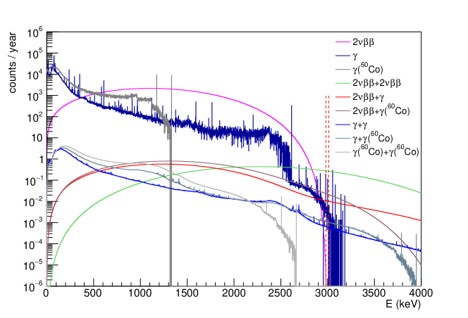
Here, we roughly estimate the pile-up event background rate. We assume two events can be separated if they are 10 cm10 cm10 cm away when the second event happens. Note that, 10 cm is roughly the size of a 0 event in SeF6 gas at a pressure of 1 MPa. This is a conservative estimation since events with lower energy dominate the background energy spectrum and are also smaller in size. With this assumption, we take the single event energy spectra for various backgrounds, do a convolution and a proper normalization, and obtain the pile-up event background energy spectra in Fig. 14 and 15 for NDEx-100 using natural SeF6 gas and enriched 82SeF6 gas, respectively.
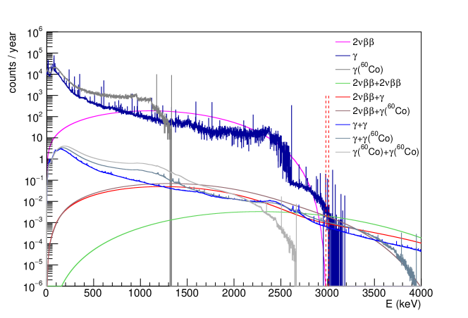
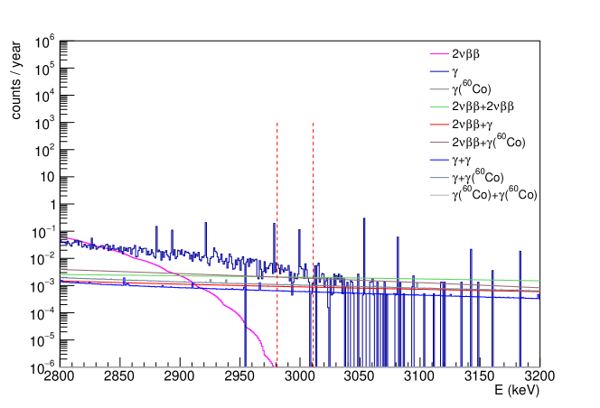
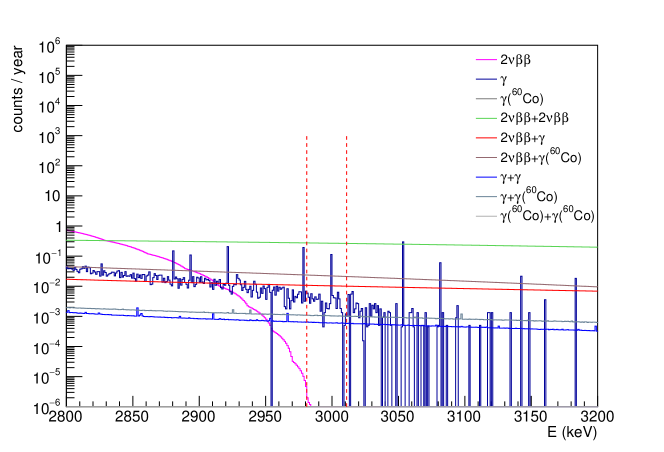
From the plots, the highest pile-up background component is 2 + 2 background for the NDEx-100 experiment with natural SeF6 gas, contributing to 0.06 evts/yr in ROI. However, this rate is still lower than that of a single-event natural radiation background.
For the NDEx-100 experiment with enriched 82SeF6 gas, the 2 + 2 pile-up background is at the level of eight evts/yr in ROI, which is higher than that of a single-event natural radiation background. Thus, pile-up background suppression should be considered in the future for the NDEx-100 experiment with enriched 82SeF6 gas. With a full simulation of charge drift, diffusion, and read-out responses, a more careful study of pile-up backgrounds can be conducted in the future, which will be more precise than the current conservative estimation. Event topology information can also be used with neural networks to reduce the contribution of pile-up events by distinguishing pile-up events from double beta decay events. For example, a 2 + 2 pile-up event with two pairs of tracks should look different from a single event, with only one pair of tracks starting from the same position. If the pile-up backgrounds cannot be suppressed to be smaller than the single-event background with software alone, adding scintillation light detection at the HV plane side using silicon PM and light guides is also an option to explore in the future. The SeF6 gas scintillation characteristics must be studied to do this. If needed, other scintillator gases may be mixed into the 82SeF6 gas to increase the scintillation light yield. The HV plane may also need to be changed to a mesh to allow scintillation light to go through. If more scintillation light events than drift ion events are observed within a certain drift time, some drift ion events should be pile-up events and should be rejected for further analysis. With scintillation light read-out, which can easily separate signals from two events happening several ns apart, pile-up background events can be rejected almost completely.
IV.6 Sensitivity Estimation
If NDEx-100 is successfully developed and reaches the background level listed above, the dominant background contribution is due to natural radiation , at the level of 0.4 evts / yr in ROI before suppression using event topology information.
According to studies in Nygren et al. (2018), the neural network can further suppress the background by a factor of about 10, while keeping a 90% signal efficiency when event topology information is used. So, the final background level is 0.05 evts / yr in ROI. After five years of operation, the background is about 0.25 events in ROI. Thus, NDEx-100 is almost a zero-background experiment.
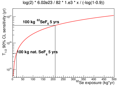
For simplicity, the NDEx-100 experiment sensitivity is calculated assuming zero background, as shown in Fig.16. We can see that the sensitivity can reach yrs at 90% confidence level after five years of operation with 100kg of natural SeF6 gas. If enriched 82SeF6 gas is used, the sensitivity can reach yrs at 90% confidence level after five years of running, which is better than the current best sensitivity of yrs from the KamLAND-Zen experiment Abe et al. (2023).
V Summary
In summary, NDEx-100 is a 100-kg scale neutrinoless double beta experiment conducted in the China Jinping Underground Laboratory using a high-pressure SeF6 gas TPC. The topmetal-S sensors have been developed to read out drift ion signals in the NDEx TPC with the electronegative SeF6 gas. All sub-systems of NDEx-100, including the pressure chamber and inner copper shielding, TPC field cage, readout plane and data acquisition system, external shielding, gas system, and the negative-pressure clean room, have been completed in the conceptual design and are described in this report. NDEx-100 is being developed, with installation completion at CJPL planned for 2025. Combining the advantages of the high (2.996 MeV) of 82Se and TPC’s ability to distinguish signal and background events using their different topological characteristics, NDEx-100 can achieve a very low background level of 0.05 evts / yr in ROI and high sensitivity of () yrs at 90% confidence level after five years of operation, using 100 kg of natural SeF6 (enriched 82SeF6) gas.
References
- Mohapatra and Senjanovic (1980) R. N. Mohapatra and G. Senjanovic, Neutrino Mass and Spontaneous Parity Nonconservation. Phys. Rev. Lett. 44, 912 (1980). doi:10.1103/PhysRevLett.44.912 .
- Agostini et al. (2020) M. Agostini et al. (GERDA), Final Results of GERDA on the Search for Neutrinoless Double- Decay. Phys. Rev. Lett. 125, 252502 (2020). doi:10.1103/PhysRevLett.125.252502 .
- Aalseth et al. (2018) C. E.Aalseth et al. (Majorana), Search for Neutrinoless Double- Decay in 76Ge with the Majorana Demonstrator. Phys. Rev. Lett. 120, 132502 (2018). doi:10.1103/PhysRevLett.120.132502 .
- Adams et al. (2022) D. Q. Adams et al. (CUORE), Search for Majorana neutrinos exploiting millikelvin cryogenics with CUORE. Nature 604, 53 (2022). doi:10.1038/s41586-022-04497-4 .
- Augier et al. (2022) C. Augier et al., Final results on the decay half-life limit of 100Mo from the CUPID-Mo experiment. Eur. Phys. C . 82, 1033 (2022). doi:10.1140/epjc/s10052-022-10942-5 .
- Abe et al. (2023) S. Abe et al. (KamLAND-Zen), Search for the Majorana Nature of Neutrinos in the Inverted Mass Ordering Region with KamLAND-Zen. Phys. Rev. Lett. 130, 051801 (2023). doi:10.1103/PhysRevLett.130.051801 .
- Anton et al. (2019) G. Anton et al. (EXO-200), Search for Neutrinoless Double- Decay with the Complete EXO-200 Dataset. Phys. Rev. Lett. 123, 161802 (2019). doi:10.1103/PhysRevLett.123.161802 .
- Wang et al. (2017) L. Wang et al. (CDEX), First results on 76Ge neutrinoless double beta decay from CDEX-1 experiment. Sci. China Phys. Mech. Astron. 60, 071011 (2017). doi:10.1007/s11433-017-9038-4 .
- Ni et al. (2019) K. Ni et al. (PandaX-II), Searching for neutrino-less double beta decay of 136Xe with PandaX-II liquid xenon detector. Chin. Phys. C 43, 113001 (2019). doi:10.1088/1674-1137/43/11/113001 .
- Xue et al. (2017) M.X. Xue, Y.L. Zhang, H.P. Peng et al., Study of CdMoO4 crystal for a neutrinoless double beta decay experiment with 116Cd and 100Mo nuclides. Chin. Phys. C 41, 046002 (2017). doi:10.1088/1674-1137/41/4/046002 .
- Zhao et al. (2017) J. Zhao, L.J. Wen, Y.F. Wang et al., Physics potential of searching for decays in JUNO. Chin. Phys. C 41, 053001 (2017). doi:10.1088/1674-1137/41/5/053001 .
- Gomez-Cadenas et al. (2011) J. J. Gomez-Cadenas, J. Martin-Albo, M. Sorel et al., Sense and sensitivity of double beta decay experiments. JCAP 06, 007 (2011). doi:10.1088/1475-7516/2011/06/007 .
- Nygren et al. (2018) D. R. Nygren, B. J. P. Jones, N. López-March et al., Neutrinoless Double Beta Decay with 82SeF6 and Direct Ion Imaging. JINST 13, P03015 (2018). doi:10.1088/1748-0221/13/03/P03015 .
- Gao et al. (2019) C. Gao, M. An, G. Huang et al., A Low-Noise Charge-Sensitive Amplifier for Gainless Charge Readout in High-Pressure Gas TPC. PoS TWEPP2018, 083 (2019). doi:10.22323/1.343.0083 .
- You et al. (2021) B. You, L. Xiao, X. Sun et al., A distributed readout network ASIC for high-density electrode array targeting at neutrinoless double-beta decay search in a Time Projection Chamber. Nucl. Instrum. Meth. A 988, 164871 (2021). doi:10.1016/j.nima.2020.164871 .
- Anderson et al. (2016) J. Anderson, K. Bauer, A. Borga et al., FELIX: a PCIe based high-throughput approach for interfacing front-end and trigger electronics in the ATLAS Upgrade framework. Journal of Instrumentation 11, C12023 (2016). doi:10.1088/1748-0221/11/12/C12023 .
- Chen et al. (2020) K. Chen, H. Chen, J. Huang et al., A Generic High Bandwidth Data Acquisition Card for Physics Experiments. IEEE Transactions on Instrumentation and Measurement 69, 4569 (2020). doi:10.1109/TIM.2019.2947972 .
- Allison et al. (2006) J. Allison et al., Geant4 developments and applications. IEEE Trans. Nucl. Sci. 53,270 (2006). doi:10.1109/TNS.2006.869826 .
- Agostinelli et al. (2003) S. Agostinelli et al. (GEANT4), GEANT4–a simulation toolkit. Nucl. Instrum. Meth. A 506, 250 (2003). doi:10.1016/S0168-9002(03)01368-8 .
- Allison et al. (2016) J. Allison et al., Recent developments in Geant4. Nucl. Instrum. Meth. A 835, 186 (2016). doi:10.1016/j.nima.2016.06.125 .
- Brown et al. (2018) D. Brown, M. Chadwick, R. Capote et al., ENDF/B-VIII.0: The 8th Major Release of the Nuclear Reaction Data Library with CIELO-project Cross Sections, New Standards and Thermal Scattering Data. Nuclear Data Sheets 148, 1 (2018), special Issue on Nuclear Reaction Data. doi:10.1016/j.nds.2018.02.001 .
- Ma et al. (2021) H. Ma, Z. She, W. H. Zeng et al., In-situ gamma-ray background measurements for next generation CDEX experiment in the China Jinping Underground Laboratory. Astropart. Phys. 128, 102560 (2021). doi:10.1016/j.astropartphys.2021.102560 .
- Alvarez et al. (2012) V. Alvarez et al. (NEXT), NEXT-100 Technical Design Report (TDR): Executive Summary. JINST 7, T06001 (2012). doi:10.1016/10.1088/1748-0221/7/06/T06001 .
- Böhlen et al. (2014) T. T. Böhlen, F. Cerutti, M. P. W. Chin et al., The FLUKA Code: Developments and Challenges for High Energy and Medical Applications. missing Nucl. Data Sheets 120, 211 (2014). doi:10.1016/j.nds.2014.07.049 .
- Ferrari et al. (2005) A. Ferrari, P. R. Sala, A. Fasso, and J. Ranft, FLUKA: A multi-particle transport code (Program version 2005). doi:10.2172/877507 .
- Battistoni et al. (2015) G. Battistoni et al., Overview of the FLUKA code. Annals Nucl. Energy 82, 10 (2015). doi:10.1016/j.anucene.2014.11.007 .
- Ahdida et al. (2022) C. Ahdida et al., New Capabilities of the FLUKA Multi-Purpose Code. Front. in Phys. 9, 788253 (2022). doi:10.3389/fphy.2021.788253.
- Hu et al. (2017) Q. Hu et al., Neutron background measurements at China Jinping underground laboratory with a Bonner Multi-sphere Spectrometer. Nucl. Instrum. Meth. A 859, 37 (2017). doi:10.1016/j.nima.2017.03.048 .
- Wang et al. (2023) Q. Wang, Z. Huang, P. Hu et al., Neutron Activation Background in the NvDEx Experiment (2023). arXiv:2307.12785 [physics.ins-det] .
- Back and Ramachers (2008) J. Back and Y. Ramachers, ACTIVIA: Calculation of isotope production cross-sections and yields. Nuclear Instruments and Methods in Physics Research Section A: Accelerators, Spectrometers, Detectors, and Associated Equipment 586, 286 (2008). doi:10.1016/j.nima.2007.12.008 .
- Laubenstein and Heusser (2009) M. Laubenstein and G. Heusser, Cosmogenic radionuclides in metals as indicator for sea level exposure history. Applied Radiation and Isotopes 67, 750 (2009). doi:10.1016/j.apradiso.2009.01.029 .
- Guo et al. (2021) Z. Guo et al. (JNE), Muon flux measurement at China Jinping Underground Laboratory. Chin. Phys. C 45, 025001 (2021). doi:10.1088/1674-1137/abccae .