Anisotropic plates with architected tendon network
Abstract
We synthesize geometrically tailorable anisotropic plates by combining button shaped fish-scale like features on soft substrates, then lacing them with high-stiffness strings. This creates a new type of biomimetic architectured structure with multiple broken symmetries. First, the tendons and scales together break the symmetry of the bending response between the concave and convex curvature. Next, the weave pattern of the tendons further breaks symmetry along the two directors of plates. The anisotropy is clearly evident in 3-point bending experiments. Motivated by these experiments and the need for design, we formulate the analytical energy-based model to quantify the anisotropic elasticity and tailorable Poisson’s ratio. The derived architecture-property relationships can be used to design architected tendon plates with desirable properties.
Slender unremarkable substrates can be transformed into materials with extraordinary mechanical properties with an additional metastructure on one side. This has recently been exploited in biomimetic fish scale-inspired designs Ebrahimi et al. (2021); Buehler (2006); Wegst et al. (2015); Helfman et al. (2009); Ghosh, Ebrahimi, and Vaziri (2014); Hossain, Ebrahimi, and Ghosh (2022), membrane tensegrity Skelton et al. (2001); Lu and Skelton (1998); Zhang and Ohsaki (2015) and metasurfaces He et al. (2018); Arbabi et al. (2017); Badawe, Almoneef, and Ramahi (2016); Martini and Maci (2014). However, adapting them for active structures require complex integration of stimuli-repsosive materials or intricate fluidic circuits. Thus, many of the benefits accrue with additional complexity. Hence, tailorability of properties become increasingly difficult putting a limit on their ultimate technological impact.
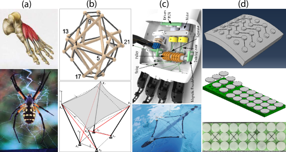
Tendons, which can be used to transmit force, Fig 1(a) are string like structures whose intricate arrangements are often exploited in nature, for instance to transfer force from muscles to bones. Thus strings are one of the most versatile structure to act and distribute forces. They find numerous engineering applications such as tensegrity, used in tensegrity, Fig. 1(b), lightweight deployable structures and soft robotics, Fig. 1(c). Thus, strings can provide an easy way to impose tension and force on membranes without additional actuator complexity. Thus woven and tendon designs Jeong et al. (2021) remains one of the most exciting areas in modern soft and wearable applications. With the advent of new types of fibersBundhoo et al. (2009), periodic tendon networks can create novel metastructures capable of tunable and tailorable mechanical properties. The tendons themselves could be replaced by actuators such as coiled actuators Zhang et al. (2020); Souza et al. (2019), thermal actuators Rodrigue et al. (2017); Knick et al. (2019), and humidity actuators Wang et al. (2018); Pu et al. (2022). Strings with suitable mechanical configurations, such as twisted strings of actuators and strings of pearls have advantages due to their lightweight, tailorability, and silent operation. Rutherford et al. (2015); Usman et al. (2017); Souza et al. (2019); Jang, Song, and Ryu (2022); Popov, Gaponov, and Ryu (2013).
Specifically, the architecture of the periodic network or weave of the tendons can be exploited to create desirable mechanical stiffness when integrated with a substrate. Such designs lead to metastructures with unique and tailorable mechanical properties not seen in conventional designs. In Fig. 1(d) different tendon structures are shown that were used in our study. The string side bending (positive) can result in additional stiffness due to string tension whereas the other side retains the behavior of the underlying substrate only to jam/lock as the buttons touch each other. This creates a tailorable bi-directional metastructure. In spite of such promises, little work has been done to systematically understand and model the resulting metastructure. The lack of architecture-property relationships hinders further design driven growth and exploration. Relationships between anisotropic and asymmetric plate bending, effect on Poisson ratio and contrast in bi-directional properties are not in the literature. We address this gap for the first time by systematic derivation of closed form relationships using energy principles Mousanezhad et al. (2016).
To motivate our study, we fabricated the tendon samples using a multi-step manufacturing method that included a soft substrate, a button (used as an anchor), and string. We create a mold with dimension . A 3D (UltimakerTM) printer was used to fabricate the mold of the substrate and button (Polylactic acid, PLA) (). In order to create the soft substrate, mixtures of silicon rubber (Dragon SkinTM 10) and curing material were cast into the mold. The button was encapsulated into the soft substrate without using adhesive after allowing the substrate to cure and which was then removed from the mold. Finally, we wound the string (Power Pro Spectra Fiber Braided Line) () in four different arrangements to conduct the experiment, the string were wrapped once around the buttons..
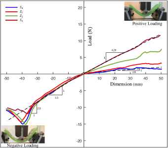
To demonstrate the difference between various weaves, a 3-point bending experiment was performed using MTS Insight® under displacement control at a crosshead speed of 1mm/s with cross-head displacement from . Here, we tested eight distinct samples with buttons placed next to each other with minimal gap. These samples included: without string (), with one zigzag string () (at an angle of ), with two zigzag string () (at an angle of ), and two straight string (at an angle of ), as shown in table I1. We used string side loading (positive loading) and button side loading (negative loading) for obtaining the stiffness. The load cell values were acquired in relation to the cross-head displacement.
| Test Samples | Symbols | Representation of loading |
|---|---|---|
| Without String | 1. String side loading | |
| One ZigZag String |
![[Uncaptioned image]](/html/2304.02547/assets/Positive_loading.jpg)
|
|
| Two ZigZag String | 2. Button side loading | |
| Two straight String |
![[Uncaptioned image]](/html/2304.02547/assets/Negative_loading.jpg)
|
The load vs displacement curve for positive and negative loading is shown in Fig. 2. The load-displacement curve shows two fundamentally different behaviors on the sides of loading. The string side stiffness is significantly higher for and then decreases in the order of and when compared to baseline (no string). Eventually, the stiffness plateaus due to string slippage and transition from string extension mode to button bending mode that show similar stiffness for all samples. On the other hand, the behavior on the reverse side is unfettered by the strings as they are not engaged. Eventually, the structure reaches a geometrically dictated locking/jamming configuration when the buttons touch each other. These results inspire us to develop a mathematical architecture-property for the string-substrate systems.
Our mathematical model considers a single type of unit cell that of type. ’s geometrical parameters can encompass all the other unit cells considered in this work. Fig. 3(a-c) displays the three different types of strings and their corresponding unit cells.
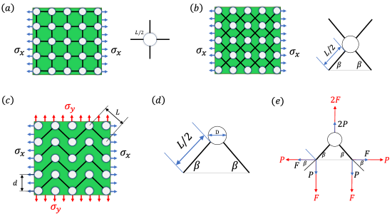
For the unit cell, we treat string and substrate as elastic material and the buttons as rigid. We take and as the modulus of elasticity of substrate and string respectively.
The length of the string, its radius, and the perpendicular distance between the two button edges are denoted as , , and respectively. To load the system, a stress of in the direction of the x-axis and a stress of in -direction is applied. Fig. 3(e) illustrates the force operating in the -direction (blue) and -direction (red) as a result of the stress. The forces acting in the direction and direction respectively are and , where is the angle of sting with horizontal line. Note that this load is based on the assumption that in-plane condition on the tendon metastructure is that plain stress.
To find out the structure’s Young’s modulus and Poisson ratio in the and direction, virtual force is applied in the -direction (blue) for -directional stress. Another virtual force of magnitude is applied on the -direction to calculate the Young’s modulus and Poisson ratio in -direction. Note that the actual magnitude of the fictitious force is unimportant for application of energy methods. the -direction (red) for -directional load as shown in Fig. 3(e). Eq. (1) represents the strain energy of the unit cell due to stress in the -direction and Eq. (2) represents the strain energy due to stress in the -direction, where A is the cross-sectional area of cell walls and is the second moment of the area of the string structure.
| (1) |
| (2) |
From here, using Castigliano’s theorem (i.e. ), we calculated the structure’s average strain ( for the -direction and for the -direction) (see Supplementary Material). Thus, the structure’s modulus of elasticity was determined by the ratio of average stress for -direction and for direction. Poisson’s ratio for the necessary load directions was established using the ratio of the change of displacement in transverse direction to the axial direction (see Supplementary Material). For the string-substrate structure, we have the Poisson effect for both the string metastructure and membrane material. To determine the overall modulus of elasticity we volume average the elastic constants. Thus, for finding the overall Poisson ratio of the structure, we employed a volumetric weighted ratio (i.e. in -direction, ) that combines the Poisson’s ratios of the individual components to allow calculating the overall Poisson’s ratio of the substrate (see Supplementary Materials).
Based on the developed material properties, we calculated the equation for the bending moments , and . using the Kirchhoff plate theory shown in Eq. (3) and Eq. (4). Here, is the correction factor that arises due to additional stiffness of the button inserts (inclusion effect). Such inclusion factors can be computed using FE simulations. The flexural rigidity of a plate is given by and . Where and represent the combined Poisson ratio (that we achieved from volumetric weighted average of Poisson ratio for substrate and string), and and is the combined modulus of elasticity (from volumetric weighted average of modulus of elasticity for substrate and string) in the and -directions, respectively (see Supplemental material).
| (3) |
| (4) |
In the negative loading, the strings are not engaged and hence the stiffness is independent of weave and the same as the substrate. However, eventually, at sufficiently large curvatures, the buttons engage with each other leading to a geometrically locked/jammed configuration, shown in Fig 4(d). This locking curvature can be obtained via the geometry of the buttons and bending kinematics. For this purpose, we define , , , and the button’s diameter, the height of the button, substrate angular change (related to curvature ), and the distance between the buttons respectively. From the Fig. 4(d) (top) which represents a unit cell, we find two curvature relations and . This leads to button size and lattice spacing relation with curvature lock, .
For validating these results, we use commercially available finite element (FE) based simulation software ABAQUS/CAE 2021 (Dassault Systémes). The digital models were made to conform to the analytical model. The buttons were subjected to rigid body constraints, which eliminated the need for button material attributes. During the simulation, the material properties have been used similar to the properties used for the calculation of mathematical modeling. The substrate’s Poisson ratio and modulus elasticity were estimated to be and , respectively. Also, the string’s Poisson ratio and modulus elasticity were taken as and , respectively. These numbers are close to the physical system considered. However, the model is not tied to these exact numbers. A total of twelve unit cells were considered to represent the string-substrate system. The effect of non-linearity during the simulation was negligible and hence the bending of the structure was modeled using a static step with a linear geometry option. The center of the beam’s cross-section was fixed, and rotation was applied to both ends of the -direction and -direction during the study of the respective directions. Sufficient mesh density was used in order to achieve mesh convergence. For the simulations, approximately 338868 Quadratic tetrahedron element C3D10 (standard quadratic 3D stress elements) were used that were standard quadratic 3D stress elements.
We first plot the bending rigidity of the tendon metastructures in both and direction according to the weave angle for positive direction bending. This is illustrated in Fig. 4(a) which plots, nondimensionalized (where, ) against the angle for both the theoretical and FE outcomes. The FE models showed excellent match with analytical calculations. We found that with the increase of angle along the horizontal axis, the stiffness in the -direction decreased, whereas the opposite is true for -direction. Thus the contrast in anisotropy between the two directions can be increased sharply by changing the weave angle as the trends are opposite. Not surprisingly, at the angle of weave (balanced weave), the stiffnesses in both directions are the same. Hence, the overall structure becomes symmetric. It is worth noting that the change in stiffness in both directions with angle is nonlinear but with opposite rates of increase in two directions. The sensitivity to beta is much higher in -direction at higher beta whereas the reverse is true for -direction. Thus, much higher stiffness gains can be achieved in one direction with varying angle keeping the other direction stiffness relatively unchanged.
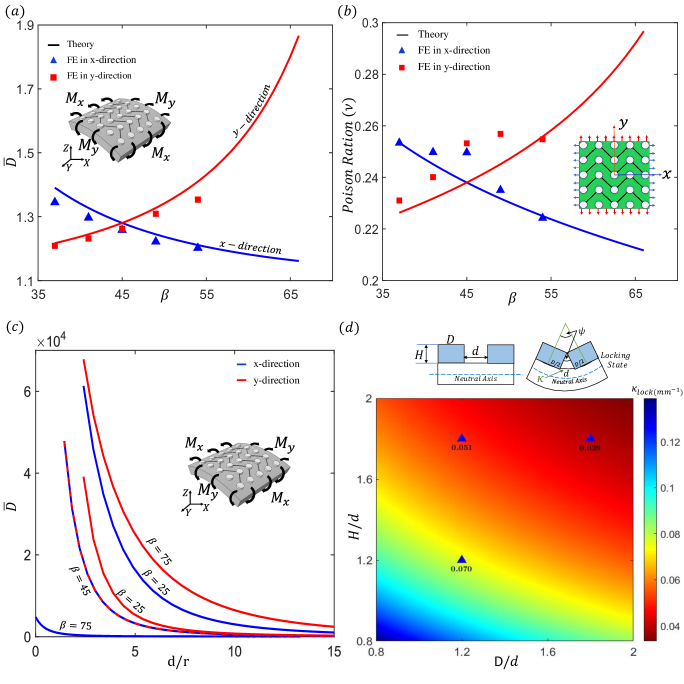
Fig. 4(b) we plot the combined Poisson ratio of the string-substrate meta structure against different angles for both directions for positive direction bending. As the angle increases, there is a decrease in the effective poison ratio for the -direction while the opposite holds true for the -direction. We have once again observed a similar anisotropic trend in the Poisson ratio at different angles, as was previously seen in stiffness. The Poisson ratio shows some discrepancy between numerical and theoretical values. the average discrepancy was roughly 5% and maximum 10%. The major reason for the discrepancy could be amplification of errors arising from the two directions of calculations in the previous step. Another reason is the inaccuracies in measuring average Poisson’s ratio from numerical calculations alone. We anticipate that larger number of unit cells would reduce this discrepancy. Similar to stiffness, the Poisson ratio also exhibits greater sensitivity in the -direction as the angle increases.
Fig. 4(c) represents bending rigidity with respect to normalized string length, i.e. . In other words, the geometric tailorability of the substrate with respect to button lattice spacing. We find that bending rigidity significantly decrease for all angles with increasing button lattice spacing. The gains are nonlinear and the highest gains in rigidity occur at the lowest . Interestingly, the loss in stiffness with increased lattice spacing can be counteracted by higher winding angle of the weave. These plots indicate a complex inter-relation between the string lattice spacing and string weave with respect to gain in bending stiffness. This would have implications in functionally graded designs with various string gages.
Fig. 4(d) shows the phase plot of locking curvature at different vs in the negative direction. The locking curvature is a measure of range of motion of the structure in the negative direction. The plots show excellent agreement with FE results. The plot clearly shows that both wider and taller buttons reduce the range of motion. The isocurvature lines appear to be hyperbolic. This is supported by the scaling law emerging from the locking relationship, . Thus, higher spacing leads to rapid increase in range of motion. For very large spacing , we get . This result is essentially same as the locking limit of scale covered substrates Ghosh, Ebrahimi, and Vaziri (2014). However, note that in practice this curvature may be larger than the physical limit of the substrate bending before it closes onto itself.
In conclusion in this paper, we derived architecture-property relationship. We motivate our work using the 3-point bending test on the samples revealed that the bending stiffness was a function of both the weave geometry and the spacing of the buttons over which winding was carried out. We derived structure-property relationships for the tendon network that allowed us to quantify the effect of weave parameter on stiffness. Our results revealed significant anisotropy of the resultant metastructure. The nature of the string allowed bi-directional asymmetry (between two directions of bending). The structure-property relationships were nonlinear with disproportionate sensitivity towards wound angles for some directions. Our calculations on Poisson’s ratio also showed that it can be depressed by adjusting the weave. In spite of this auxeticity was not observed.
Thus, our work lays the foundation of a new type of metastructure that is capable of building a system with tuneable material properties by utilizing the mathematical model established in this letter. Which could be used to make metamaterials. This string substrate system can also be used in soft robotics by swapping out the string for shape memory alloy.
This work was supported by the United States National Science Foundation’s Civil, Mechanical, and Manufacturing Innovation, CAREER Award #1943886.
References
- Ebrahimi et al. (2021) H. Ebrahimi, H. Ali, J. Stephen, and R. Ghosh, “Fish scales: Primitive basis for modern metamaterials,” EPL (Europhysics Letters) 133, 68001 (2021).
- Buehler (2006) M. J. Buehler, “Nature designs tough collagen: explaining the nanostructure of collagen fibrils,” Proceedings of the National Academy of Sciences 103, 12285–12290 (2006).
- Wegst et al. (2015) U. G. Wegst, H. Bai, E. Saiz, A. P. Tomsia, and R. O. Ritchie, “Bioinspired structural materials,” Nature materials 14, 23–36 (2015).
- Helfman et al. (2009) G. Helfman, B. B. Collette, D. E. Facey, and B. W. Bowen, The diversity of fishes: biology, evolution, and ecology (John Wiley & Sons, 2009).
- Ghosh, Ebrahimi, and Vaziri (2014) R. Ghosh, H. Ebrahimi, and A. Vaziri, “Contact kinematics of biomimetic scales,” Applied Physics Letters 105, 233701 (2014).
- Hossain, Ebrahimi, and Ghosh (2022) M. S. Hossain, H. Ebrahimi, and R. Ghosh, “Fish scale inspired structures-a review of materials, manufacturing and models,” Bioinspiration & Biomimetics (2022).
- Skelton et al. (2001) R. E. Skelton, R. Adhikari, J.-P. Pinaud, W. Chan, and J. Helton, “An introduction to the mechanics of tensegrity structures,” in Proceedings of the 40th IEEE conference on decision and control (Cat. No. 01CH37228), Vol. 5 (IEEE, 2001) pp. 4254–4259.
- Lu and Skelton (1998) J. Lu and R. E. Skelton, “Optimal hybrid control for structures,” Computer-Aided Civil and Infrastructure Engineering 13, 405–414 (1998).
- Zhang and Ohsaki (2015) J. Zhang and M. Ohsaki, Tensegrity structures, Vol. 7 (Springer, 2015).
- He et al. (2018) Q. He, S. Sun, S. Xiao, and L. Zhou, “High-efficiency metasurfaces: principles, realizations, and applications,” Advanced Optical Materials 6, 1800415 (2018).
- Arbabi et al. (2017) A. Arbabi, E. Arbabi, Y. Horie, S. M. Kamali, and A. Faraon, “Planar metasurface retroreflector,” Nature Photonics 11, 415–420 (2017).
- Badawe, Almoneef, and Ramahi (2016) M. E. Badawe, T. S. Almoneef, and O. M. Ramahi, “A true metasurface antenna,” Scientific reports 6, 1–8 (2016).
- Martini and Maci (2014) E. Martini and S. Maci, “Metasurface transformation theory,” Transformation Electromagnetics and Metamaterials: Fundamental Principles and Applications , 83–116 (2014).
- Jeong et al. (2021) U. Jeong, K. Kim, S.-H. Kim, H. Choi, B. D. Youn, and K.-J. Cho, “Reliability analysis of a tendon-driven actuation for soft robots,” The International Journal of Robotics Research 40, 494–511 (2021).
- Bundhoo et al. (2009) V. Bundhoo, E. Haslam, B. Birch, and E. J. Park, “A shape memory alloy-based tendon-driven actuation system for biomimetic artificial fingers, part i: design and evaluation,” Robotica 27, 131–146 (2009).
- Zhang et al. (2020) J. Zhang, D. Bombara, S. Fowzer, and C. Brennan, “Compliant and large-strain twisted string actuators using supercoiled polymers,” in 2020 3rd IEEE International Conference on Soft Robotics (RoboSoft) (IEEE, 2020) pp. 201–207.
- Souza et al. (2019) S. A. Souza, P. Muehlbauer, S. Janzen, J. Liu, and P. P. Pott, “Series and parallel actuation array of elastic micro-twisted string actuators,” in IKMT 2019-Innovative small Drives and Micro-Motor Systems; 12. ETG/GMM-Symposium (VDE, 2019) pp. 1–5.
- Rodrigue et al. (2017) H. Rodrigue, W. Wang, M.-W. Han, T. J. Kim, and S.-H. Ahn, “An overview of shape memory alloy-coupled actuators and robots,” Soft robotics 4, 3–15 (2017).
- Knick et al. (2019) C. R. Knick, D. J. Sharar, A. A. Wilson, G. L. Smith, C. J. Morris, and H. A. Bruck, “High frequency, low power, electrically actuated shape memory alloy mems bimorph thermal actuators,” Journal of Micromechanics and Microengineering 29, 075005 (2019).
- Wang et al. (2018) W. Wang, C. Xiang, Q. Liu, M. Li, W. Zhong, K. Yan, and D. Wang, “Natural alginate fiber-based actuator driven by water or moisture for energy harvesting and smart controller applications,” Journal of Materials Chemistry A 6, 22599–22608 (2018).
- Pu et al. (2022) W. Pu, F. Wei, L. Yao, and S. Xie, “A review of humidity-driven actuator: toward high response speed and practical applications,” Journal of Materials Science 57, 12202–12235 (2022).
- Rutherford et al. (2015) S. Rutherford, R. M. Demianiuk, J. Benamou, C. Beckett, M. G. Ness, and L. M. Déjardin, “Effect of intramedullary rod diameter on a string of pearls plate-rod construct in mediolateral bending: an in vitro mechanical study,” Veterinary Surgery 44, 737–743 (2015).
- Usman et al. (2017) M. Usman, B. Suthar, H. Seong, E. Hawkes, I. Gaponov, and J.-H. Ryu, “Passive returning mechanism for twisted string actuators,” in 2017 IEEE International Conference on Robotics and Automation (ICRA) (IEEE, 2017) pp. 3714–3719.
- Jang, Song, and Ryu (2022) J. Jang, Y.-U. Song, and J.-H. Ryu, “Active-type continuously variable transmission system based on a twisted string actuator,” IEEE Robotics and Automation Letters 7, 2605–2612 (2022).
- Popov, Gaponov, and Ryu (2013) D. Popov, I. Gaponov, and J.-H. Ryu, “Bidirectional elbow exoskeleton based on twisted-string actuators,” in 2013 IEEE/RSJ International Conference on Intelligent Robots and Systems (IEEE, 2013) pp. 5853–5858.
- Mousanezhad et al. (2016) D. Mousanezhad, B. Haghpanah, R. Ghosh, A. M. Hamouda, H. Nayeb-Hashemi, and A. Vaziri, “Elastic properties of chiral, anti-chiral, and hierarchical honeycombs: A simple energy-based approach,” Theoretical and Applied Mechanics Letters 6, 81–96 (2016).
- Skelton and De Oliveira (2009) R. E. Skelton and M. C. De Oliveira, Tensegrity systems, Vol. 1 (Springer, 2009).
- Zhang et al. (2018) L.-Y. Zhang, S.-X. Li, S.-X. Zhu, B.-Y. Zhang, and G.-K. Xu, “Automatically assembled large-scale tensegrities by truncated regular polyhedral and prismatic elementary cells,” Composite Structures 184, 30–40 (2018).
- Yang and Sultan (2016) S. Yang and C. Sultan, “Modeling of tensegrity-membrane systems,” International Journal of Solids and Structures 82, 125–143 (2016).
- Tavakoli, Batista, and Sgrigna (2015) M. Tavakoli, R. Batista, and L. Sgrigna, “The uc softhand: Light weight adaptive bionic hand with a compact twisted string actuation system,” in Actuators, Vol. 5 (MDPI, 2015) p. 1.