Aerostack2: A Software Framework for Developing Multi-robot Aerial Systems
Abstract
In recent years, the robotics community has witnessed the development of several software stacks for ground and articulated robots, such as Navigation2 and MoveIt. However, the same level of collaboration and standardization is yet to be achieved in the field of aerial robotics, where each research group has developed their own frameworks. This work presents Aerostack2, a framework for the development of autonomous aerial robotics systems that aims to address the lack of standardization and fragmentation of efforts in the field. Built on ROS 2 middleware and featuring an efficient modular software architecture and multi-robot orientation, Aerostack2 is a versatile and platform-independent environment that covers a wide range of robot capabilities for autonomous operation. Its major contributions include providing a logical level for specifying missions, reusing components and sub-systems for aerial robotics, and enabling the development of complete control architectures. All major contributions have been tested in simulation and real flights with multiple heterogeneous swarms. Aerostack2 is open source and community oriented, democratizing the access to its technology by autonomous drone systems developers.
Source code:
https://github.com/aerostack2/aerostack2
Documentation:
https://aerostack2.github.io/
I Introduction
In recent years, the robotics community has witnessed the development of several software stacks focused on the control and guidance of ground robots and articulated robots. Navigation2 [1] and MoveIt [2] are two examples of such that have gained widespread adoption. However, the same level of collaboration and standardization has not been observed in the field of aerial robotics. Research groups have tended to develop their own frameworks, resulting in isolated efforts that are difficult to integrate.
Furthermore, even when frameworks have been developed, they often have a narrow focus, such as low-level control, which limits their usefulness in more comprehensive applications. This fragmentation of efforts can make it challenging to take advantage of the strengths of each framework in a common application.
To address these challenges, this paper proposes a collaborative framework for aerial robotics that brings together users and developers to work towards a common goal. Building on the work of others, we aim to enhance research in aerial robotics and accelerate their application in industry fields. This paper presents an overview of our proposed framework and discusses its potential impact in the field.
The presented software framework Aerostack2 is an evolution of a former one called Aerostack [3] which was developed and successfully used in our research lab for more than six years, not only for research purposes, but also for industrial projects and international robotics competitions like MBZIRC 2020 or IMAV 2017.
Our framework, presented in this paper, incorporates important changes and improvements to enable more efficient and effective robotic systems. Specifically, the framework operates using ROS 2 (Robotics Operating System 2 [4]), a widely used middleware for robotics that provides valuable tools to create modular and distributed robotic systems. Additionally, the framework is built on a more efficient modular software architecture and enables multi-robot orientation. Moreover, the framework aims to foster community creation within the ROS 2 ecosystem, as seen in other widely used software frameworks in the Robotics Community.
Contributions
Compared to other existing solutions in the drone sector, Aerostack2 is an original tool mainly because of the following characteristics:
-
•
Platform Independence. Aerostack2 is a general environment, not dedicated to specific aerial platforms, so it can be used with different types of drones. For example, Aerostack has been used on drones with Pixhawk controllers or with commercial platforms (e.g., DJI).
-
•
Versatility. Aerostack2 covers a wide range of robot capabilities for autonomous operation with different types of mechanism related to flight control, spatial localization, aerial navigation planning methods, forms of communication between drones, etc.
-
•
Easy mission specification. Aerostack2 provides a logical level that helps developers formulate the tasks to be done by autonomous aerial robots. Compared to the level provided by ROS2 programming, this logical level abstracts details (e.g., using the notion of robot behaviors) and simplifies the specification of missions. In addition, an existing robotic system developed using Aerostack2 may be used by operators to formulate aerial misions with the help of mission specification tools (e.g., user interfaces, behavior trees, etc.).
-
•
Simplify the engineering process in aerial robots systems. Aerostack2 provides pre-programmed components that provide autonomous operation capabilities, encapsulating specialized algorithms (computer vision, sensor data fusion, automatic planning, motion controllers, etc.). These components are designed in a general and adaptable way to be used in the construction of multiple aerial robots. Individual Aerostack2 components (e.g., a flight motion controller) can be reused to build specific aerial robotic applications. In this case, the developer does not use the complete framework, but only separate components for specific functionalities. Component reuse may be done at different levels of granularity (e.g., simple algorithms, complex robot behaviors, etc.). For example, a developer who designs a new algorithm for a certain aerial robot capability (e.g., a flight motion controller) may test such an algorithm by reusing a partial architecture provided by Aerostack2.
-
•
Open-source. The Aerostack2 environment is open source and free of charge, which facilitates universal access to this technology by autonomous drone developers. Aerostack is offered with a BSD-3-Clause license that allows free distribution and modification of the software.
II Related Work
There are numerous flight systems of different nature that allow UAVs to fly. A common division in the literature is between low-level control systems, typically the flight controller, and high-level control systems, flight, or aerial stacks.
Low-level control systems vary from open source hardware (OSH) and open source software (OSS) to proprietary commercial controllers. In 2018 Ebeid et al. presented a survey of open-source hardware and software comparing their main features [5]. Table I shows a comparison of relevant flight controllers.
| Flight Controller | Open Source | Simulation | Rate Input |
|---|---|---|---|
| Pixhawk/PX4 | OSH, OSS | SITL, HITL | ✓ |
| Ardupilot | OSS | SITL, HITL | ✓ |
| Paparazzi | OSH, OSS | SITL, HITL | ✓ |
| Crazyflie | OSH, OSS | SITL, HITL | ✓ |
| DJI Matrice | Propietary | HITL | ✓ |
| Parrot | Propietary | SITL | ✗ |
| Skydio | Propietary | - | ✗ |
-
•
OSH: Open Source Hardware, OSS: Open Source Software, SITL: Software In The Loop, HITL: Hardware In The Loop.
Several high-level control systems has been published in the recent years. Table II compares existing aerial stacks with the proposed solution of this publication.
| Flight Stack | Open Source | Modular | Tested in | Middle-ware | Soft. last update | Multi-frame | Rate output | Multi-agent | Multi-platform | Plugin oriented |
| Aerostack [3] | ✓ | ✓ | S,RL,RO | ROS | 10/2021 | ✗ | ✓ | ✓ | ✓ | ✗ |
| AerialCore [6] | ✓ | ✓ | S,RL,RO | ROS | 03/2023 | ✓ | ✓ | ✓ | ✗ | ✓ |
| Agilicius [7] | ✓ | ✓ | S,RL | ROS | 03/2023 | ✗ | ✓ | ✗ | ✗ | ✗ |
| KumarRobotics [8] | ✓ | ✗ | S,RL,RO | ROS | 12/2022 | ✗ | ✓ | ✗ | ✓ | ✗ |
| CrazyChoir [9] | ✓ | ✗ | S,RL | ROS 2 | 02/2023 | ✗ | ✓ | ✓ | ✗ | ✗ |
| UAL [10] | ✓ | ✗ | S,RL,RO | ROS | 12/2022 | ✓ | ✗ | ✗ | ✓ | ✗ |
| XTDrone [11] | ✓ | ✓ | S | ROS | 03/2023 | ✗ | ✓ | ✗ | ✗ | ✗ |
| RotorS [12] | ✓ | ✓ | S | ROS | 07/2021 | ✗ | ✓ | ✗ | ✗ | ✗ |
| GAAS [13] | ✓ | ✓ | S | ROS | 10/2021 | ✗ | ✗ | ✗ | ✗ | ✗ |
| Aerostack2 (Ours) | ✓ | ✓ | S,RL,RO | ROS 2 | 03/2023 | ✓ | ✓ | ✓ | ✓ | ✓ |
-
•
S: Simulation, RL: real experiments in the lab, RO: real experiments outside the lab.
Aerostack [3] is a software framework that helps developers design and build the complete control architecture of aerial robotic systems, integrating multiple heterogeneous computational solutions (e.g., computer vision algorithms, motion controllers, self-localization and mapping methods, motion planning algorithms, etc.). Aerostack was developed in our research laboratory using ROS. The experience in its use and the development of successive versions has been an important antecedent for the creation of the new framework presented in this paper.
AerialCore [6] is an aerial system built using ROS Noetic and meant to be executed entirely onboard. It can be deployed on any multi-rotor vehicle, given it is equipped with a PX4-compatible flight controller, for both indoor and outdoor. It supports multi-robot experiments using Nimbro network communication and provides both: agile flying and robust control.
Agilicious [7] is a co-designed hardware and software framework tailored to autonomous and agile quadrotor flight, which has been developed and used since 2016 at the Robotics and Perception Group (RPG) of the University of Zurich. It is completely open-source and open-hardware and supports both model-based and neural network-based controllers. Also, it provides high thrust-to-weight and torque-to-inertia ratios for agility, onboard vision sensors, GPU-accelerated compute hardware for real-time perception and neural-network inference, a real-time flight controller, and a versatile software stack.
KumarRobotics flight stack [8] allows a quadrotor to navigate autonomously in cluttered and GPS-denied environments. It consists of a set of modules that work together to allow fast autonomous navigation of an aerial robot through an unknown environment. The system has been designed so that all sensing and computation occurs onboard the robot. Once the robot has been launched, there is no human interaction necessary for the robot to navigate to the goal.
CrazyChoir [9] is a ROS 2 toolbox that allows users to run simulations and experiments on swarms of Crazyflie nano-quadrotors. CrazyChoiR implements several tools to model swarms of Crazyflie nano-quadrotors and to run distributed, complex tasks both in simulation and experiments.
UAV Abstraction Layer (UAL) [10] is a software layer to abstract users of unmanned aerial vehicles from the specific hardware of the platform and the autopilot interfaces. Its main objective is to simplify the development and testing of higher-level algorithms in aerial robotics by trying to standardize and simplify the interfaces with unmanned aerial vehicles. Unmanned aerial vehicle abstraction layer supports operation with PX4 and DJI autopilots (among others), which are current leading manufacturers. Besides, unmanned aerial vehicle abstraction layer can work seamlessly with simulated or real platforms and provides calls to issue standard commands such as taking off, landing or pose, and velocity controls.
XTDrone [11] is a UAV simulation platform based on PX4, ROS, and Gazebo. XTDrone supports mulitrotors (including quadrotors and hexarotors), fixed wings, VTOLs (including quadplanes, tailsitters, and tiltrotors), and other unmanned systems (such as UGVs, USVs, and robotic arms). It is convenient to deploy the algorithm to real UAVs after testing and debugging on the simulation platform.
RotorS [12] is a modular Micro Aerial Vehicle (MAV) simulation framework, which allows a quick start to perform research on MAVs. The simulator was designed in a modular way so that different controllers and state estimators can be used interchangeably, while incorporating new MAVs is reduced to a few steps. The provided controllers can be adapted to a custom vehicle by simply changing a parameter file. Different controllers and state estimators can be compared with the provided evaluation framework. All components were designed to be analogous to their real-world counterparts. This allows the usage of the same controllers and state estimators, including their parameters, in the simulation as on the real MAV.
Generalized Autonomy Aviation System (GAAS) [13] is an open-source program designed for fully autonomous VTOL and drones. GAAS provides a fully autonomous flight platform based on lidar, HD-map relocalization, path planning, and other modules for aircraft. In contrast to the autopilot technology previously available only for consumer-grade drones, GAAS aims for robust fully autonomous flight for human-carrying and can be easily combined with national air traffic control. The whole framework is loosely coupled, so you can customize your own modules and easily add them to GAAS.
Of the nine high-level control systems analyzed, it is observed that (1) all of them are open source; (2) six have a modular structure; (3) four systems have been tested in a non-laboratory environment, two on a real robot and three only in simulation; (4) only one of the systems, CrazyChoir, uses ROS 2 as middleware, compared to ROS used by the rest; (5) six systems have undergone an update in the last six months; (6) only two, AerialCore and UAL, support references in different frames; (7) seven of the systems support acro control of the aircraft; (8) three systems have a multi-agent approach; (9) three other systems support more than one different flight platform; and (10) only AerialCore has an architecture oriented towards the use of plugins.
III A Stack of Software Components for Aerial Robotics
Aerostack2 framework is organized in the form of a software stack with components distributed in different hierarchical layers, as can be seen in Fig. 1. Components are organized hierarchically in several layers in such a way that components at one layer may use components of the lower layers (corresponding to less complex functionalities) but they do not use components of the higher layers. The layers are the following (from bottom to top):
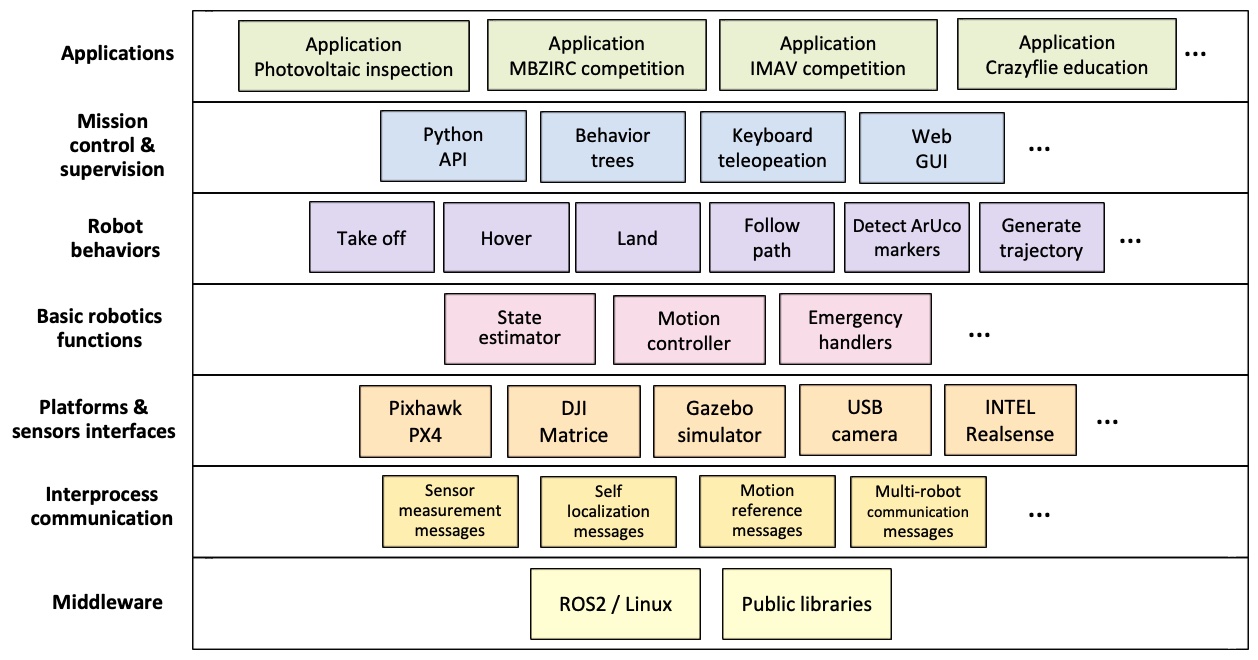
-
•
Middelware. At the lowest level is the software that supports the Aerostack2 environment, which consists of the Linux operating system and ROS (Robot Operating System), as well as general software libraries (e.g. OpenCV).
-
•
Inter-process communication. It includes components to facilitate communication between processes that operate concurrently. These are message types for information exchange that define data structures (specific to aerial robotics) that are common to facilitate process interoperability.
-
•
Interfaces with platforms and sensors. These are components that serve as interfaces with multiple kinds of aerial platforms and sensors. Aerostack2 has several interfaces that allow operating with both physical platforms (e.g., with Pixhawk or with DJI platforms) and simulated platforms (e.g., using simulated drones with the Gazebo environment) besides different types of sensor (e.g., USB cameras, RealSense depth camera).
-
•
Basic robotics functions. Aerostack2 includes a set of software components that implement specialized algorithms corresponding to essential aerial robotics functions for autonomous operation such as state estimation, motion control, and other basic functions (e.g., emergency handling, etc.).
-
•
Behaviors. This level includes a set of components corresponding to different robot behaviors provided by Aerostack2 for autonomous operation. Each component encapsulates the algorithms used to implement a particular behavior (e.g., take off, hover, generate trajectory, etc.) together with mechanisms for execution monitoring to facilitate the specification of mission plans.
-
•
Mission control. This level includes components that facilitate the specification of missions for autonomous drone operation. For example, behavior trees can be used to indicate and visualize with a hierarchical graphical structure the tasks performed by the drone. On the other hand, Aerostack2 also provides an API (application programming interface) that allows one to specify missions in a flexible way using the Python language. Additionally, Aerostack2 provides tools for the user to monitor and manually control the mission execution.
-
•
Applications. The top level corresponds to the specific applications built with the components of the lower levels. Aerostack2 has examples of applications that can serve developers as a reference and guide on how to build drones that operate autonomously. In addition to applications with real drones, Aerostack2 has multiple applications in simulated environments with varying degrees of complexity to facilitate the learning of this technology.
It is important to note that this modular organization of components is open to be used at any layer. This means that developers who use Aerostack2 may use directly the top-level components but also may use separately any intermediate layer or other individual component (e.g., the state estimator) for building a particular application. The following sections describe in more detail each layer of the software stack.
III-A Interprocess communication
In order to organize each robot control architecture with multiple interacting processes operating concurrently, Aerostack2 has a standard data channel that is shared among the processes. To facilitate process interoperability, the content of the data channel follows conventions defined by standards that are applicable to aerial robotics. These standards are defined with respect to data structures and common names for communication mechanisms between processes (e.g., ROS 2 topics, services, and actions). Our framework follows some standards that have been defined by the ROS 2 community for aerial robots, and others (e.g., more specific message types or names of ROS 2 topics, services, and actions) have been defined specifically in Aerostack2. Table III illustrates some of the ROS topics used by Aerostack2 together with standard names and standard message types.
The content of the standard data channel is distributed in the following main groups:
-
•
Sensor measurements. Sensor measurements are values corresponding to direct measurements recorded by sensors. This includes, for example, images from cameras, data from IMU, data from GPS, etc.
-
•
Actuator commands. These messages correspond to commands that are directly understandable aerial platforms, such as thrust or, depending on the platform, values about the desired localization.
-
•
Self localization. These values correspond to the robot localization in the environment together with kinematic values (e.g., speed) as they are believed by the robot. These values may be obtained, for example, by fusing sensor measurements with the help of extended Kalman filters (EKF).
-
•
Motion reference. These messages are motion values that should be considered as goals by motion controllers. This includes, for example, desired values for pose, speed, trajectory, etc.
-
•
Others: multi-robot communication messages, alert messages corresponding to emergency situations, operation mode of the aerial platform, etc.
| ROS topic name | Message type | Description |
|---|---|---|
motion_reference/pose
|
geometry_msgs/PoseStamped
|
Actuator command for the multirotor specifying x, y, and z (m: meters) and roll, pitch and yaw (rad: radians). |
motion_reference/twist
|
geometry_msgs/TwistStamped
|
Actuator command for the multirotor specifying vx, vy and vz (m/s: meters per seconds) and roll rate, pitch rate and yaw rate (rad/s: radians per seconds). |
motion_reference/trajectory
|
as2_msgs/TrajectoryPoint
|
Reference trajectory point specifying x, y and z (m: meters), vx, vy and vz (m/s: meters per seconds), ax, ay, and az (m/s²: meters per seconds squared) and yaw angle (rad: radians). |
sensor_measurement/camera
|
sensor_msgs/Image
|
Raw image data received from camera (a general camera). |
sensor_measurement/imu
|
sensor_msgs/Imu
|
Inertial Measurement Unit data. |
sensor_measurement/gps
|
sensor_msgs/NavSatFix
|
GPS (Global Positioning System) coordinates. |
III-B Platforms and sensors interfaces
The common data channel presented in the previous section includes sensor and actuator data represented in a generic way that is independent of the physical platform used. This makes it possible to make part of the control architecture independent of the different platforms to be used, which facilitates the reuse of its components. The way to connect the architecture with each platform is through the construction of interfaces between the platform and the communication channel.
Aerostack2 incorporates a Platform abstraction class responsible for managing the capabilities associated with the direct integration of various aerial platforms into the framework. This abstraction facilitates the integration of new platforms into the framework by providing guidance on integration steps, overloading functions of the Platform class, and ensuring compatibility with the entire framework.
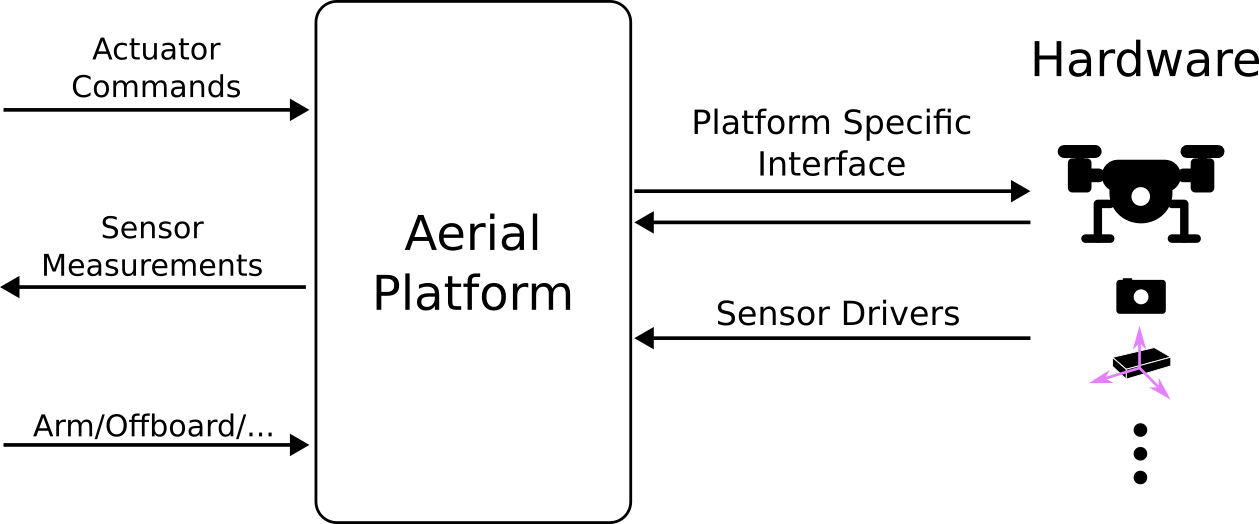
The proposed framework’s interaction with the Platform interface facilitates the integration of both physical and simulated interfaces, without requiring the rest of the framework to distinguish between the two. This feature is a fundamental pillar that strengthens the sim2real capabilities of the framework.
The responsibility of this interface is to gather sensor measurements from the aircraft and transmit them to the Communication Layer. Additionally, it is tasked with receiving actuator commands and other requests from the various layers of the Aerostack2 framework and relaying them to the aircraft in a platform-specific manner.
Moreover, there may be instances where additional sensors or actuators are required for a specific application, such as controlling a mounted arm or manipulating a different sensor. To address this, Aerostack2 incorporates the Sensor abstraction class, which simplifies the management of external sensors. It should be noted that the Aerostack2 framework is fully compatible with all ROS 2 drivers, enabling easy integration with previous community efforts.
III-C Basic Robotic Functions
The Aerostack2 platform encompasses a collection of software components that perform fundamental robotic functions in aerial robotics. These components correspond to functions such as motion control, state estimation, and other essential functions (e.g., emergency handling, etc.) that support the autonomous operation of various types of aerial robots.
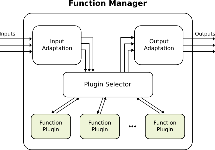
In general, Aerostack2 components are designed to be general and reusable with alternative algorithms that are implemented in the form of plug-ins and are selected based on each particular situation and aerial robotic application. But this way of structuring the components gains full sense when talking about basic robotic functions due to the importance of these modules within the functioning of the entire system.
In this architecture, the basic functions are managed by a function manager, which is responsible for loading the plugins with each concrete algorithm (e.g., a PID controller) and managing how they interact within the rest of the framework. The plugin selector can also provide meta-control features, such as plugin replacement, plugin bypass (which occurs when the motion reference can be directly handled by the aerial platform), whereas the input and output adapters, adjusts the input or output of the function plugin to the rest of the Aerostack2 framework. In Fig. 2 an schema of the architecture of a basic function is described.
Specifically, the two core functions of the framework are the following, the connection of which can be shown in Fig. 4:
-
•
Motion Control: This module listens to the motion reference commands generated from the top-level layers and converts them into actuator command signals that will be followed by the concrete aerial platform. Inside this module, the controllers process the references to generate control signals. The Controller Manager is responsible for ensuring a suitable combination of motion references, which have to be preprocessed with the current working plugin preferences (e.g. the motion references shall be expressed in the reference frame in which the controller expects), but also to adequate the actuation command signals and post-processing them for aerial platform desired format. Moreover, the plugin selector has the capability to load multiple controllers in the form of plugins, being able to be aware of the operation of each one and making the appropriate selection.
-
•
State Estimator: This module combines the information received from different sensors to estimate the state of the aircraft, where the state refers to the position and speed of each aircraft over time. This module can load multiple state estimation algorithms in the form of plugins. The State Estimator Manager is responsible for generating the transformation trees (TF trees) that will be used by the rest of the framework. In addition, it is aware of the available plugins and is able to make the selection based on the environment. In addition, it is aware of the available plugins and is able to make the selection based on the environment.
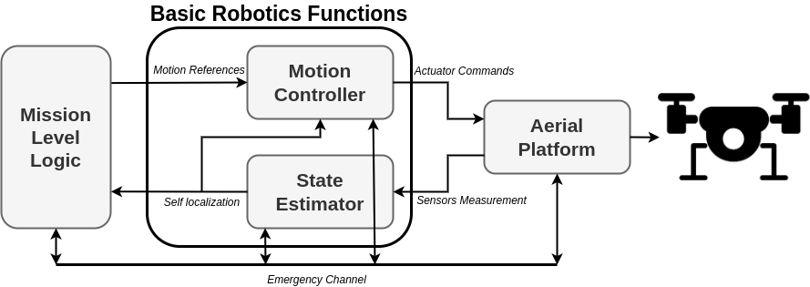
In this category of components, there are also other components, such as emergency handlers, that implement emergency procedures to react quickly in the presence of unexpected situations, such as battery discharge or approaching forbidden areas. There are multiple agents that can trigger these emergencies, and depending on the severity of the emergency, the module corresponding to a low-level layer will handle it. For example, if the severity is low, the controller may be able to handle it, but if it is severe, the aerial platform itself should act.
III-D Behaviors
Aerostack2 uses a specialized type of component, called behavior, which provides a logical layer to formulate mission plans in a uniform and more simplified way (compared to the direct use of state estimators and actuator controllers). Each behavior corresponds to a specific robot skill related, for example, to flight motion, such as taking off, landing, hovering and following a path, or other abilities (e.g., video recording, communication with other agents, etc.).
Using behaviors, a mission plan is expressed as a controlled sequence of activations (or deactivations) of multiple behaviors that may operate concurrently. Each behavior activation initiates the execution of a particular task described with certain parameters (e.g., following a particular path described with a list of waypoints). The result of each behavior execution is described in terms of success or failure, which is useful to determine the next step to be done during the mission.
We distinguish between two types of robot behaviors, according to execution goals111This division is also mentioned in the literature of robotics. For example, these two categories have been distinguished using the terms servo, for recurrent behaviors, and ballistic for goal-based behaviors [14].: (1) goal-based behaviors that are defined to reach a final state or attain a goal (for example, in an aerial robot, the behavior taking off), and (2) recurrent behaviors that perform an activity recurrently or maintain a desired state (for example, a behavior for visual marker recognition).
The notion of behavior in robotics has been used in the behavior-based paradigm [15] [16] (which mainly corresponds to reactive behaviors) and in behavior-based systems [17] (with both reactive and deliberative behaviors). In particular, a behavior in Aerostack2 may correspond not only to reactive behaviors (e.g., hovering) but also to skills similar to mental abilities that use complex internal representations (e.g., generating a trajectory to reach a destination).
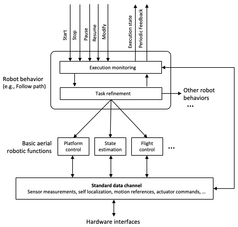
The software components that implement behaviors in the Aerostack2 framework are specialized modules for robust plan execution following a distributed organization that facilitates maintainability and flexibility to add new behaviors in the future. Each behavior provides the following two main types of functions (Fig. 5):
-
•
Task refinement. Robot behaviors execute tasks that cannot be executed directly by actuators because they are formulated in an abstract terminology as it is used to specify mission plans by the user. Robot behaviors refine these tasks into more detailed operations (e.g., references to controllers, etc.). This is done in an adaptive way in continuous interaction with the environment (e.g., waiting a certain amount of time to complete each step or selecting the most appropriate method according to the current situation of the environment).
-
•
Execution monitoring. Each robot behavior observes and assesses how each task is executed (e.g., by contrasting observations with expectations), which is very important to facilitate a robust operation. In contrast to other centralized approaches, Aerostack2 distributes execution monitoring into behaviors. For example, each behavior checks locally whether the current situation of the environment satisfies the assumptions to operate correctly (e.g., a behavior for visual marker recognition checks that the lighting assumptions in the environment are satisfied). Execution monitoring also detects when the execution has reached a prefixed goal or when there is a failure in the execution. For example, in the case of a task to follow a certain path, a failure can be detected if the robot does not arrive at the destination point in a maximum expected time or if the robot moves in the opposite direction to the direction that is expected to follow towards the destination point.
Each software component that implements a behavior encapsulates the details of the algorithms used to execute the task, providing a uniform interface that is common for all behaviors. This interface is used to control the execution of the behavior with the following basic services: start, pause, resume and stop. In addition, a service called modify is used to change parameters of a behavior without the need to stop its execution. The behavior interface is also used to inform about the execution of the behavior with two separate outputs: the execution state of the behavior (e.g., idle, running, or paused), and a periodic feedback during the execution of behavior.
The manner in which the behaviors have been implemented is fully consistent with the standard ROS 2 actions. Each behavior is linked to its own ROS2 action, with added functionalities that enable actions to be paused, resumed, or even have their goals modified during execution.
III-E Mission control and supervision
Aerostack2 provides several mechanisms that help developers specify a mission plan and supervise its execution. The developer can write a mission plan to specify the set of tasks that a robot must perform on a particular mission. The specification of mission plans can be formulated in the form of robot behaviors. In this way, the user can specify the mission more easily by indicating complex tasks that the robot executes autonomously (e.g., following a certain path).
One of the solutions provided by Aerostack2 to specify missions is a Python API (Application Programming Interface). This is a convenient method for users familiar with computer programming languages and provides high flexibility for formulating plans with complex control regimes. Aerostack2 provides an API with a set of functions to activate/deactivate behaviors or to directly send command through motion reference messages. The next piece of code shows a simple example of a mission written in Python using the API provided by Aerostack2.
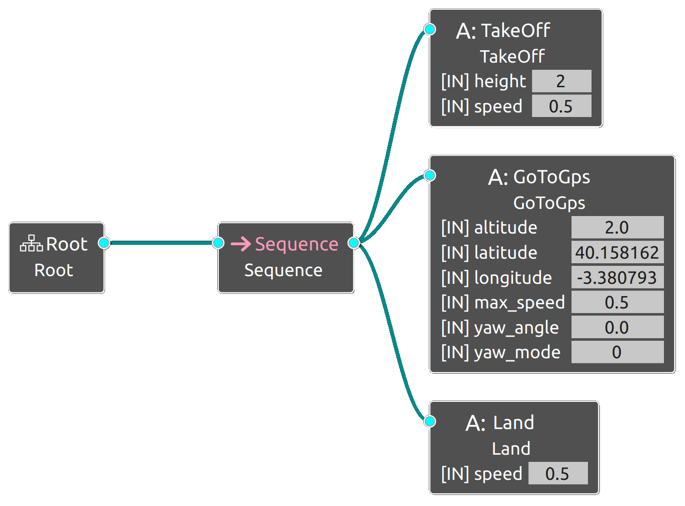
As an alternative to the Python API, the developer may use other mechanisms to specify mission plans. For example, mission plans may be formulated using behavior trees [18]. The modularity and hierarchical of behavior trees are useful during the mission plan design but also during mission execution thanks to a graphically monitoring. Aerostack2 incorporates custom behavior tree nodes that can activate and deactivate robot behaviors. Fig. 6 shows a mission sketched in a behavior tree.
It is important to note that, using these previous methods to specify mission plans, the developer has to take into account additional operational aspects to coordinate the execution considering the relationships between concurrent behaviors (e.g., incompatibility or dependency). Such coordination mechanisms may be difficult to design and implement in complex autonomous robots. In these situations, additional solutions can be used based on automatic coordination of behaviors [19].
In addition to the tools mentioned for the specification of the mission plan, Aerostack2 also provides other tools to monitor execution. This includes two user interface tools that use information related to basic aerial robotic functions: (1) an alphanumeric viewer to monitor the state of specific variables (e.g., sensor measurements, values corresponding to state estimation, references for controllers) and (2) an interface for keyboard teleoperation which can be used by the user to operate manually an aerial robot with the help of the keyboard.
The alphanumeric viewer is a powerful tool to have a overview of the system’s operation, being very useful for research and development of framework modules.
While the keyboard teleoperation is usefull tool to manipulate the dron in a simple way, sending position and speed commands, which allows one to check the system behavior or take the controll when the autonomous logic fails.
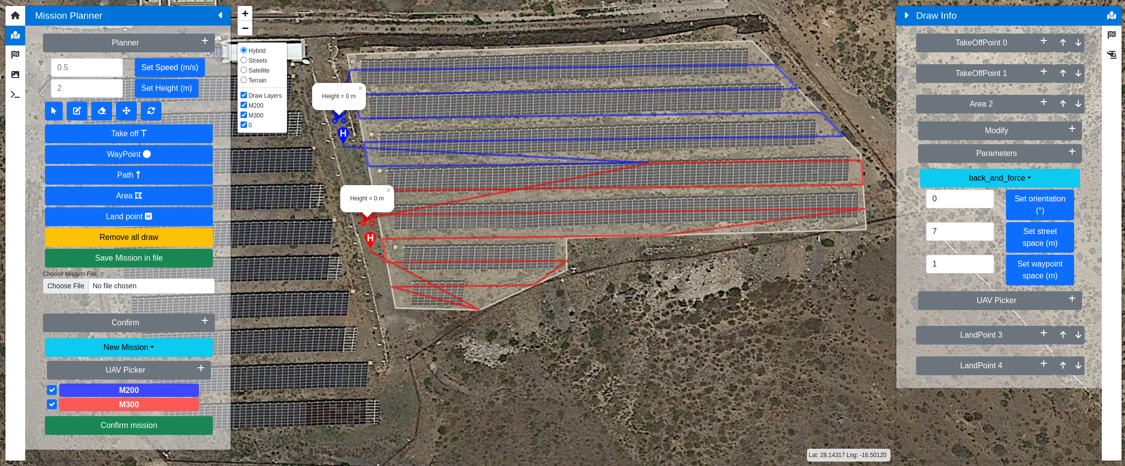
In this category of components, Aerostack2 also provides a graphical user interface for using the software framework through a web-based application. This type of tool is very convenient to facilitate rapid planning of a mission for one or several drones using graphical resources (e.g., a geographic map and graphical references), which can be done online or offline, allowing repeatability of missions, as shown in Fig. 8. This user interface is also useful to show graphically details of the mision execution, allowing its monitoring and modification in real time.
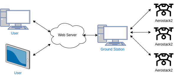
The schematic of this interface is shown in Fig. 7, where many users can connect through different devices and communicate with the agents through the network. This architecture provides the ability to plan and supervise missions from different devices, making the system robust and powerful to use. In addition, since it is a web interface, it can be used from any device, increasing its accessibility.
IV Experiments & Discussion
This section presents some experiments that show the capabilities of Aerostack2 performing drone swarming missions.
IV-A Sim2Real
This experiment studies the ease of moving from an experiment performed in a simulation environment to the real world. In this scenario, two drones have to cross two gates in a coordinated way.
The simulation was performed using Gazebo Ignition. The mission was planned using the python API of Aerostack2. For this mission just the basic behaviors are used: platform behaviors for offboarding and arming, and motion behaviors for taking off, flying, and landing. The localization of the drones and the gates are provided by the ground truth of the simulator, and for control, a PID controller with trajectory references is used.
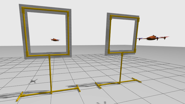
The real experiment was carried out in the CAR Robotics Arena, an area of 60 m2 with a surrounding safety net. An Optitrack motion capture system (mocap) system provides the position of drones and gates within the capture area. The UAVs used for this experiment were two Bitcraze Crazyflie 2.1 with IR markers for mocap localization. Due to the limited payload of these micro-UAVs, the computing was performed by the ground station computer.
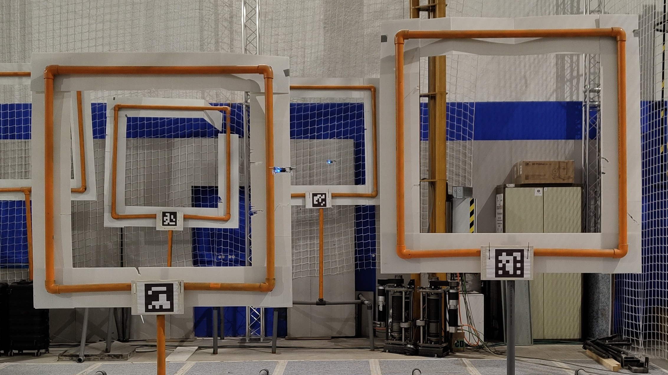
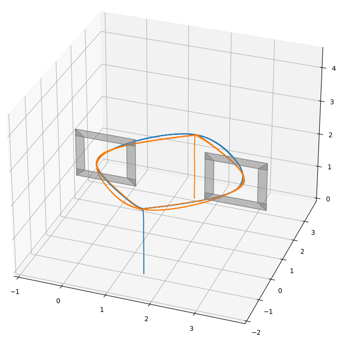
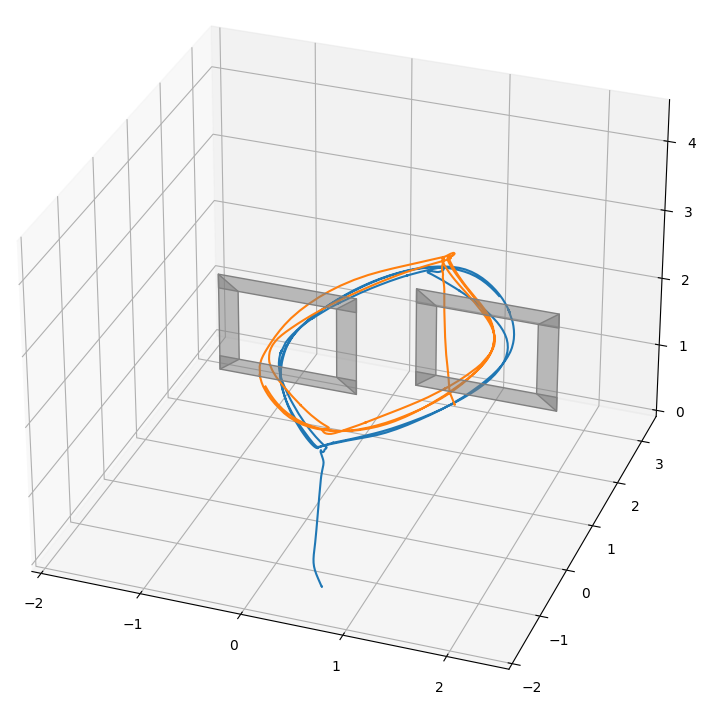
Table IV shows a comparison between the components used in simulation and real experiments. This shows that it is only needed to change the platform and the state estimation component (in this case, a plugin inside of it) to translate the experiment from simulation to the real world.
| Module | Simulation | Real |
|---|---|---|
| Mission Control | Python API | Python API |
| Behaviors | MB, PB, TGB | MB, PB, TGB |
| State Estimation | Ground Truth | Motion Capture System |
| Motion Control | PID controller | PID controller |
| Platforms | Gazebo Simulator | Crazyflie |
IV-B Heterogeneous swarm
| Module | Component |
|---|---|
| Mission Control | Web GUI |
| Behaviors | MB, PB |
| State Estimation | GPS |
| Motion Control | PID controller |
| Platforms | DJI matrice, PX4 |
In this experiment, two different platforms are used at the same time to perform a cooperative mission. These platforms, shown in Fig. 12, were:
-
•
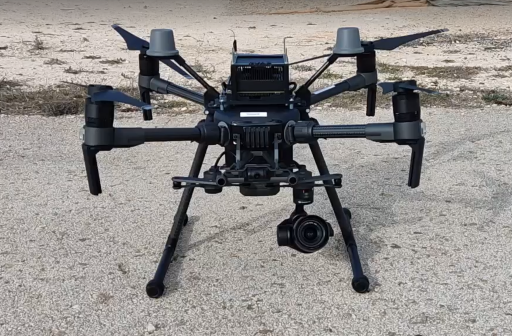
Pixhawk F450: autopilot PX4 Pixhawk 4 mini on DJI F450 frame with Nvidia Jetson Xavier NX for onboard computing, GPS, and Rangefinder as an altimeter.
-
•
DJI M210: DJI Matrice 210 RTK v2 with Nvidia Jetson AGX Xavier for onboard computing.
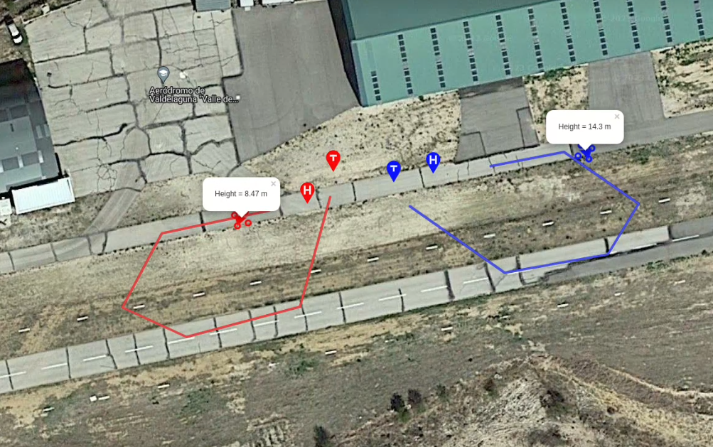
This scenario represents the use of a swarm consisting of two drones to perform a simple aerial inspection. The mission was planned using the Web GUI, generating a path of GPS waypoints for both drones from an aerial image of the flying area. Once the mission was generated, both drones took off at the same time, and each one traveled along the path, landing when they finished.
In this case, the use of two different models of drones does not make a difference for Aerostack2 when planning the mission and controlling the drones. The computing was performed onboard the drones, each drone having an instance of Aerostack2, and they communicated their position to the ground station for monitoring, allowing a high level of autonomy.
IV-C Use cases
Aerostack2 has been used for several applications:
-
•
Wind turbine inspection: in the context of an industrial project that aims to increase the autonomy of drones in wind turbine inspection, some experiments have been carried out. Fig. 14 shows a drone controlled by Aerostack2 in a simulated environment following the movement of the wind turbine during inspection. Subsequently, this simulated wind turbine was used to give references to a real drone during a flight to simulate an inspection in the real world, as shown in Fig. 15. This shows the capability of Aerostack2 to be used to mix real-world flying with simulated information.
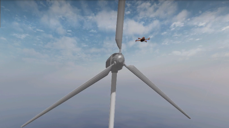
Figure 14: Wind turbine inspection in simulation. 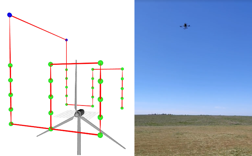
Figure 15: Wind turbine simulated inspection in a real environment. References from a simulated moving wind turbine (left) were used to move a real drone (right). -
•
Photovoltaic plant inspection: as part of the development of an industrial project, the simulation of an inspection of a photovoltaic plant was performed with a swarm of drones. This simulation was made using Gazebo and the photorealistic simulator Flightmare [20]. The mission was planned with the Web GUI, defining the limits of the inspection area. Then, a path planning algorithm generates the path over the lines of panels that must be taken to inspect the area based on the desired distance between survey points. After this, another algorithm is responsible for dividing the route into each path that each drone must follow [21]. This shows that Aerostack2 can be used for the development of industrial projects using a swarm of drones. Fig. 16 shows images taken during this experiment.
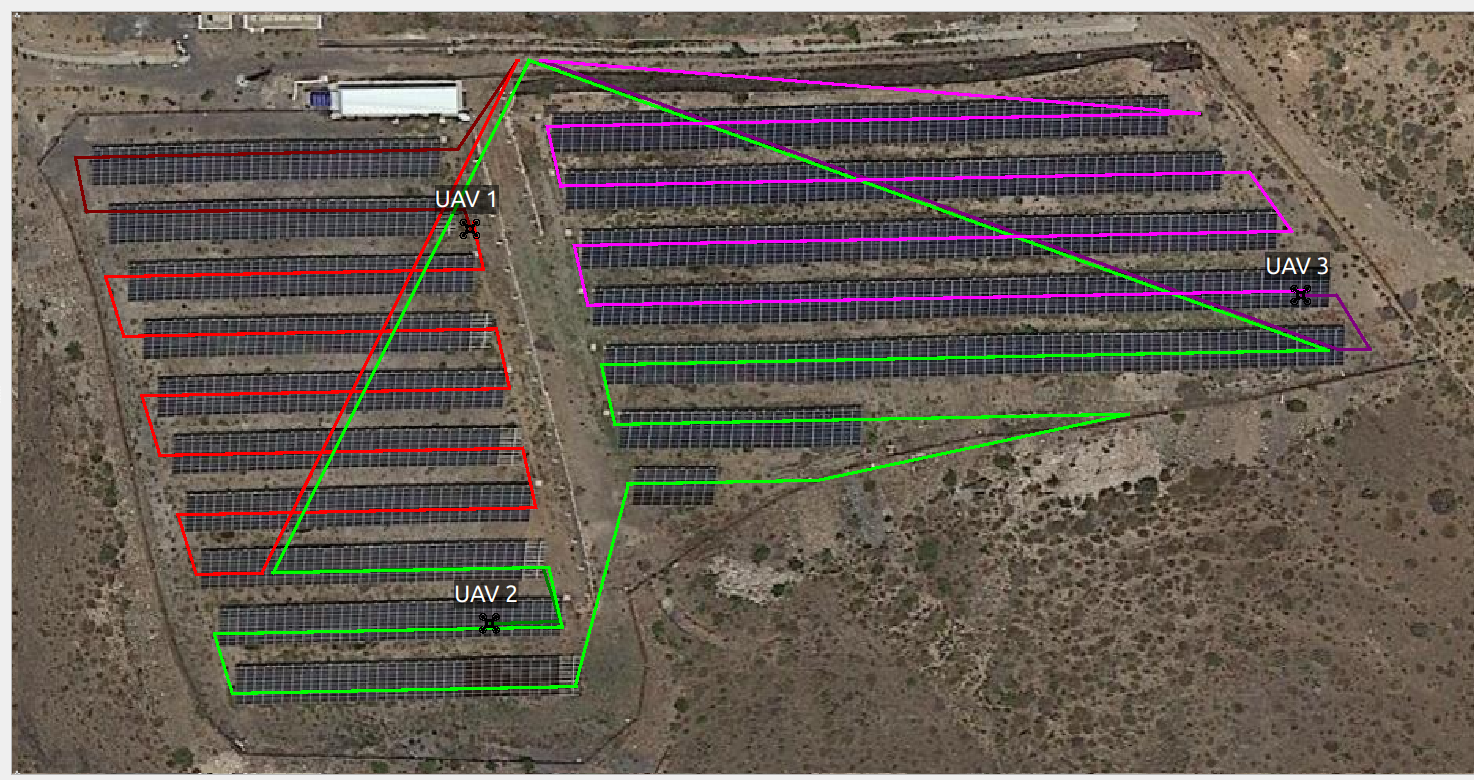
(a) Web GUI mission monitoring 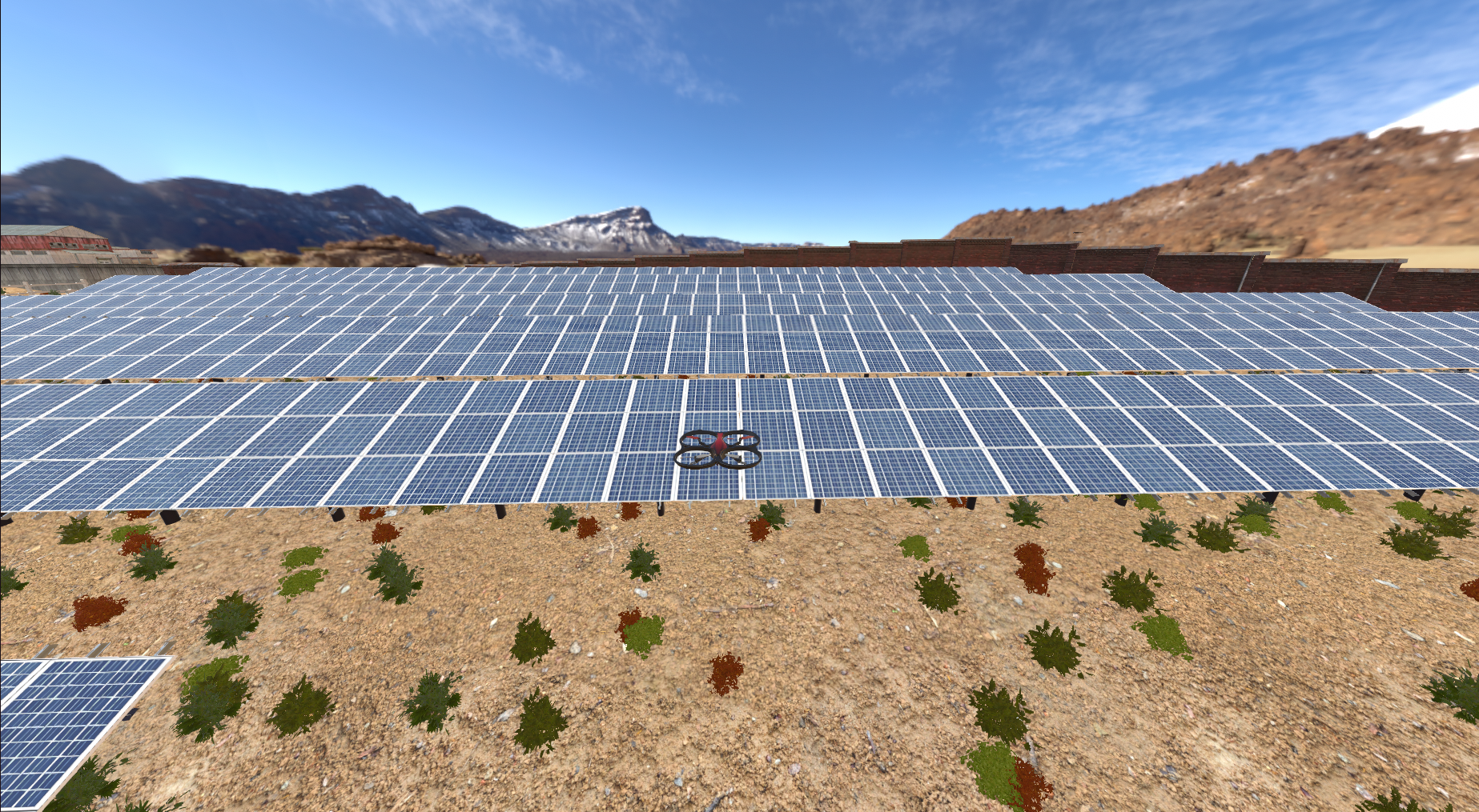
(b) Simulation environment 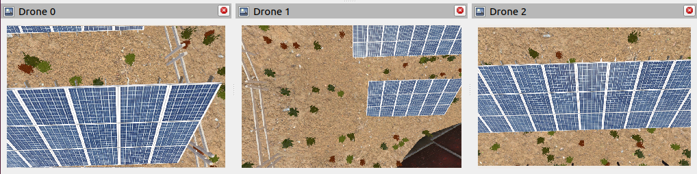
(c) Camera view from the drones Figure 16: Photovoltaic plant swarm simulated inspection. -
•
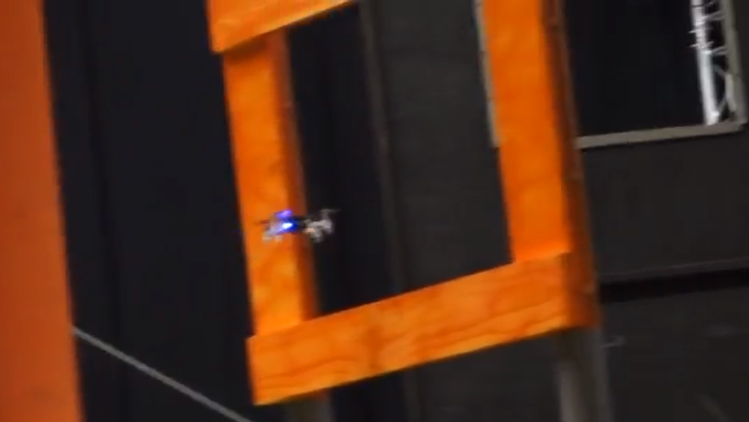
Gate crossing: AI Nanocopter Challenge within IMAV’22 consists of flying one Bitcraze Crazyflie drone inside a small arena populated with obstacles and drone racing gates. Aerostack2 was able to pilot the UAV using wifi communication, and with a segmentation color algorithm, passing through several gates, achieving the record of the highest number of gates passed by all participants. Fig. 17(a) shows the drone during this competition.
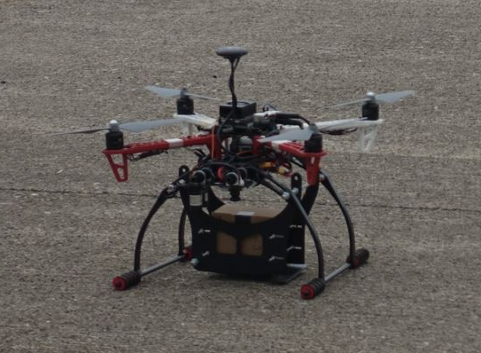
-
•
Package delivery: IMAV’22 also proposes a package delivery challenge consisting of flying a UAV carrying a package and delivering it to a certain place. The maximum weight of the UAV with the payload was 5 kg. This involved the construction of an ad hoc drone using a Pixhawk autopilot on a F450 frame with a package delivery device. In this scenario, Aerostack2 was able to plan the mission with the Web GUI and fly the drone in an outdoor environment using GPS references, as shown in Fig. 17(b).
(a) AI nanocopter 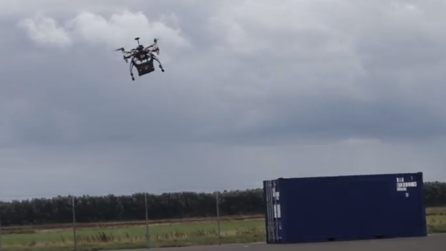
(b) Package delivery Figure 17: Using Aerostack2 during IMAV’22 in different challenges: AI nanocopter (left) and Package Delivery (right). -
•
Maritime Operation: MBZIRC’23 competition proposes a maritime operation of search and evidence collection. This challenge consists of several drones searching for a specific boat in a vast maritime area, coordinated with an unmanned surface vehicle (USV) to take some packages from this boat. The main difficulties of this scenario were the absolute lack of GPS signal, the communication distances, and the coordinated maneuvers required to transport the packages. For this phase, the scenario was recreated in a realistic simulation environment made on Gazebo. Aerostack2 served as the framework for the trials of this competition, showing the capabilities to fly several coordinated drones, using custom localization and communication algorithms, and implement neural networks for object detection, as shown in Fig. 18.

The use of Aerostack2 in these applications shows the capability of this framework to be used in very different scenarios, with completely different requirements.
V Conclusions and Future Work
This paper has presented an innovative Open Source framework for the development of aerial robot systems. The framework’s key capabilities, including multirobot orientation, platform independence, versatility, and modularity, have been demonstrated through a series of experiments conducted in diverse scenarios, both in simulation and in the real world.
Future work will involve the continued development of new behaviors, metacontrol capabilities, and the expansion of the number of behaviors, controllers, state estimators, and platforms supported by the system through collaboration with the aerial robotics community.
Acknowledgments
Funding. This work has been supported by the project COPILOT ref. Y2020\EMT6368 ”Control, Monitoring and Operation of Photovoltaic Solar Power Plants by means of synergic integration of Drones, IoT and advanced communication technologies”, funded by Madrid Government under the R&D Synergic Projects Program.
We acknowledge the support of the European Union through the Horizon Europe Project No. 101070254 CORESENSE.
This work has also been supported by the project INSERTION ref. ID2021-127648OBC32, ”UAV Perception, Control and Operation in Harsh Environments”, funded by the Spanish Ministry of Science and Innovation under the program ”Projects for Knowledge Generating”. The work of the third author is supported by the Grant FPU20/07198 of the Spanish Ministry for Universities. The work of the fifth author is supported by the Spanish Ministry of Science and Innovation under its Program for Technical Assistants PTA2021-020671.
Data and Materials. All materials are open-source accesible at https://github.com/aerostack2/aerostack2 under BSD-3-Clause license.
References
- [1] Steve Macenski, Francisco Martín, Ruffin White, and Jonatan Ginés Clavero. The marathon 2: A navigation system. In 2020 IEEE/RSJ International Conference on Intelligent Robots and Systems (IROS), 2020.
- [2] David Coleman, Ioan Sucan, Sachin Chitta, and Nikolaus Correll. Reducing the barrier to entry of complex robotic software: a moveit! case study, 2014.
- [3] Jose Luis Sanchez-Lopez, Ramón A Suárez Fernández, Hriday Bavle, Carlos Sampedro, Martin Molina, Jesus Pestana, and Pascual Campoy. Aerostack: An architecture and open-source software framework for aerial robotics. In 2016 International Conference on Unmanned Aircraft Systems (ICUAS), pages 332–341. IEEE, 2016.
- [4] Steven Macenski, Tully Foote, Brian Gerkey, Chris Lalancette, and William Woodall. Robot operating system 2: Design, architecture, and uses in the wild. Science Robotics, 7(66):eabm6074, 2022.
- [5] Emad Ebeid, Martin Skriver, Kristian Husum Terkildsen, Kjeld Jensen, and Ulrik Pagh Schultz. A survey of open-source uav flight controllers and flight simulators. Microprocessors and Microsystems, 61:11–20, 2018.
- [6] Tomas Baca, Matej Petrlik, Matous Vrba, Vojtech Spurny, Robert Penicka, Daniel Hert, and Martin Saska. The mrs uav system: Pushing the frontiers of reproducible research, real-world deployment, and education with autonomous unmanned aerial vehicles. Journal of Intelligent & Robotic Systems, 102(1):26, 2021.
- [7] Philipp Foehn, Elia Kaufmann, Angel Romero, Robert Penicka, Sihao Sun, Leonard Bauersfeld, Thomas Laengle, Giovanni Cioffi, Yunlong Song, Antonio Loquercio, et al. Agilicious: Open-source and open-hardware agile quadrotor for vision-based flight. Science Robotics, 7(67):eabl6259, 2022.
- [8] Kartik Mohta, Michael Watterson, Yash Mulgaonkar, Sikang Liu, Chao Qu, Anurag Makineni, Kelsey Saulnier, Ke Sun, Alex Zhu, Jeffrey Delmerico, Dinesh Thakur, Konstantinos Karydis, Nikolay Atanasov, Giuseppe Loianno, Davide Scaramuzza, Kostas Daniilidis, Camillo Jose Taylor, and Vijay Kumar. Fast, autonomous flight in gps-denied and cluttered environments. Journal of Field Robotics, 35(1):101–120, 2018.
- [9] Lorenzo Pichierri, Andrea Testa, and Giuseppe Notarstefano. Crazychoir: Flying swarms of crazyflie quadrotors in ros 2. arXiv preprint arXiv:2302.00716, 2023.
- [10] Fran Real, Arturo Torres-González, Pablo Ramón Soria, Jesús Capitán, and Anibal Ollero. Unmanned aerial vehicle abstraction layer: An abstraction layer to operate unmanned aerial vehicles. International Journal of Advanced Robotic Systems, 17(4):1–13, 2020.
- [11] Kun Xiao, Shaochang Tan, Guohui Wang, Xueyan An, Xiang Wang, and Xiangke Wang. Xtdrone: A customizable multi-rotor uavs simulation platform. In 2020 4th International Conference on Robotics and Automation Sciences (ICRAS), pages 55–61. IEEE, 2020.
- [12] Fadri Furrer, Michael Burri, Markus Achtelik, and Roland Siegwart. Robot Operating System (ROS): The Complete Reference (Volume 1), chapter RotorS—A Modular Gazebo MAV Simulator Framework, pages 595–625. Springer International Publishing, Cham, 2016.
- [13] Generalized autonomy aviation system.
- [14] Joseph L. Jones. Robot Programming: A Practical Guide to Behavior-Based Robotics. McGraw-Hill, 2002.
- [15] Rodney Brooks. A robust layered control system for a mobile robot. IEEE journal on robotics and automation, 2(1):14–23, 1986.
- [16] Ronald C Arkin. Behavior-based robotics. MIT press, 1998.
- [17] François Michaud and Monica Nicolescu. Behavior-based systems. Springer handbook of robotics, pages 307–328, 2016.
- [18] Michele Colledanchise and Petter Ögren. Behavior Trees in Robotics and AI. CRC Press, jul 2018.
- [19] Martin Molina and Pablo Santamaria. Behavior coordination for self-adaptive robots using constraint-based configuration. arXiv preprint arXiv:2103.13128, 2021.
- [20] Yunlong Song, Selim Naji, Elia Kaufmann, Antonio Loquercio, and Davide Scaramuzza. Flightmare: A flexible quadrotor simulator. In Conference on Robot Learning, 2020.
- [21] Marco Andrés Luna, Mohammad Sadeq Ale Isaac, Ahmed Refaat Ragab, Pascual Campoy, Pablo Flores Peña, and Martin Molina. Fast multi-uav path planning for optimal area coverage in aerial sensing applications. Sensors, 22(6):2297, 2022.