Stability of the Modulator in a Plasma-Modulated Plasma Accelerator
Abstract
We explore the regime of operation of the modulator stage of a recently proposed laser-plasma accelerator scheme [Phys. Rev. Lett. 127, 184801 (2021)], dubbed the Plasma-Modulated Plasma Accelerator (P-MoPA). The P-MoPA scheme offers a potential route to high-repetition-rate, GeV-scale plasma accelerators driven by picosecond-duration laser pulses from, for example, kilohertz thin-disk lasers. The first stage of the P-MoPA scheme is a plasma modulator in which a long, high-energy ‘drive’ pulse is spectrally modulated by co-propagating in a plasma channel with the low-amplitude plasma wave driven by a short, low-energy ‘seed’ pulse. The spectrally modulated drive pulse is converted to a train of short pulses, by introducing dispersion, which can resonantly drive a large wakefield in a subsequent accelerator stage with the same on-axis plasma density as the modulator. In this paper we derive the 3D analytic theory for the evolution of the drive pulse in the plasma modulator and show that the spectral modulation is independent of transverse coordinate, which is ideal for compression into a pulse train. We then identify a transverse mode instability (TMI), similar to the TMI observed in optical fiber lasers, which sets limits on the energy of the drive pulse for a given set of laser-plasma parameters. We compare this analytic theory with particle-in-cell (PIC) simulations and find that even higher energy drive pulses can be modulated than those demonstrated in the original proposal.
I Introduction
In a laser-plasma accelerator (LPA), plasma oscillations are driven by pushing free electrons away from an ultrashort laser pulse via the ponderomotive force. The heavier ions remain approximately stationary relative to the electrons, thus the electron-ion charge separation collectively forms a strong electric field which can be used to accelerate charged particles. The plasma wave driven in this way will have a phase velocity set by the group velocity of the laser pulse, which is well suited for the acceleration of relativistic charged particles. The accelerating gradients achievable by LPA are set by the wavebreaking field and can be on the order of 100 GV/m [1], three orders of magnitude larger than those possible in radio-frequency cavities. Here the plasma frequency , where is the electron density.
Efficient excitation of the plasma wave by a single laser pulse requires that the duration of the pulse is less than half the plasma period . For plasma densities of interest is in the 100 fs range, and hence single-pulse LPAs first became practical with the development of chirped pulse amplification (CPA) [2], which allowed joule-scale pulses to be compressed to sub-picosecond durations. Ever since, most experimental demonstrations of LPAs have used high intensity ultrashort laser pulses from Ti:sapphire CPA laser systems. However, these systems suffer from low ( 0.1-10 Hz) repetition rates [3] and poor () electrical-to-optical energy efficiencies [4]. Despite the advantages gained by being much more compact, the low efficiency and repetition rate of the laser drivers used today severely limit the number of applications for which LPAs offer an advantage over conventional, radio-frequency particle accelerators.
It is important, therefore, to consider alternative laser systems and/or develop novel approaches for driving LPAs. Contemporary thin-disk lasers are efficient and can already provide joule-scale pulses at kHz repetition rates [5, 6, 7]. However, they cannot drive a LPA directly since the small bandwidth of their gain media limits the duration of the pulses they generate to [8, 9, 10] , which is much longer than the plasma period. We note that pulses from thin-disk lasers have been compressed to a duration below , following spectral broadening via self-phase modulation in a gas [11]. However, to date this approach has been limited to pulse energies below .
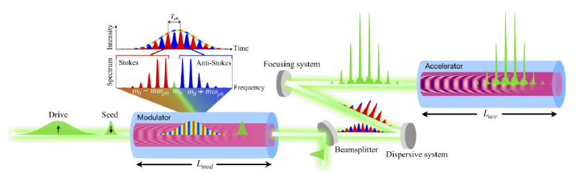
With the objective of applying the desirable features of thin-disk lasers to LPAs, some of the present authors recently proposed a scheme, illustrated in Fig. 1, for converting picosecond-duration pulses to a train of shorter pulses that could be used to resonantly excite a plasma wave [12]. In this scheme, which we call the Plasma-Modulated Plasma Accelerator (P-MoPA), a high-energy, picosecond-duration ‘drive’ pulse is modulated spectrally by co-propagating it in a plasma channel with a low amplitude () plasma wave driven by a low-energy, short ‘seed’ pulse. To first order, the spectral modulation takes the form of a set of sidebands of angular frequencies , where is the angular frequency of the input drive pulse, is the sideband order, and is the plasma frequency on the axis of the plasma channel. The spectrally-modulated drive pulse is converted into a temporal modulation by passing it through a dispersive optical system that removes the relative spectral phase, , of each sideband. This forms a train of short pulses, spaced temporally by , which can resonantly drive a large amplitude plasma wave in a plasma accelerator stage with the same axial density as the modulator.
In our earlier work a one-dimensional (1D) fluid model, and 2D particle-in-cell (PIC) simulations were used to demonstrate the operation of the plasma modulator and accelerator stages, and to show that GeV-scale energy gains could be obtained from existing thin-disk laser systems. In this paper we derive a full 3D theory of seeded spectral modulation and we use this to establish the useful operating regime for the modulator stage in the P-MoPA. We find that the range of operation of the modulator is determined by the onset of the transverse mode instability (TMI), similar to the TMI observed in high power fiber laser systems [13, 14, 15, 16, 17]. This analysis is used to establish the regime of parameter space for which the modulator can be operated successfully. The results of the 3D analytic theory are compared with particle-in-cell (PIC) simulations, and are found to be in good agreement. We find that even higher energy drive pulses can be modulated than those considered in the original proposal.
II The Plasma Modulator
II.1 Seeded Spectral Modulation in Plasma Channels
Propagation of the envelope of a laser pulse in an axisymmetric plasma channel of electron density with a small wake can be approximately described by the paraxial wave equation [18, 19, 20, 21] (see Supplemental Material [22] for its derivation)
| (1) |
where is the envelope of the pulse’s normalized vector potential, is the laser frequency and the propagation is described in co-moving coordinates , , with defined as the group velocity of electromagnetic plane waves in uniform plasma of density , corresponding to the on-axis plasma channel frequency . This group velocity may differ from the group velocity of a tightly focused laser pulse [23, 24]. Nonlinearities come from weakly relativistic effects as well as from interaction between the pulse and its own excited wake.
Successful seeded spectral modulation requires relativistic and self-wake effects to be negligible, which reduces Eq. (II.1) to a linear paraxial wave equation
| (2) |
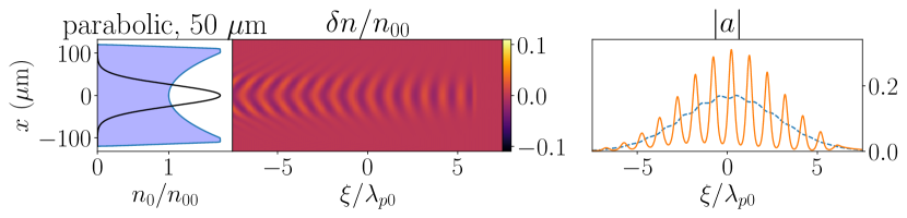
where denotes the seed pulse envelope, whose intensity we assume to be unchanging relative to the modulating drive pulse envelope . We also demand that the channel is matched to the spot size of the seed and drive pulses. A matched parabolic channel and its respective unperturbed Gaussian drive pulse envelope take the form [25, 26, 24]
| (3) |
where is the channel depth parameter, is the classical electron radius and is the slowly-varying longitudinal envelope of the drive pulse. Assuming the seed wake is small relative to the channel depth parameter , we can apply time-independent perturbation theory to Eq. (2), yielding the following modulation to the total phase of the laser pulse
| (4) |
where is the laser wavenumber with the on-axis plasma index of refraction and denotes the intensity-weighted transverse average. Using this expression we can also retrieve the shift in instantaneous frequency
| (5) |
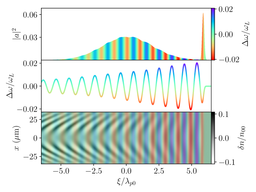
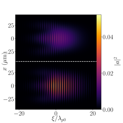
where is the modulator length. This predicts that the spectral modulation amounts to a radial averaging of the longitudinal gradient of the wake weighted by the transverse intensity profile of the drive pulse. This independence of the spectral modulation of radial position is desirable as it allows the spectral modulation to be converted into a temporal one by applying the same chromatic dispersion across the entire cross-section of the modulated pulse. Figure 2 shows the results of a 2D PIC simulation which demonstrates that the spectral modulation is indeed independent of the transverse coordinate, despite the fact that the amplitude and phase of the plasma wave does depend on the radial coordinate, as predicted by Eq. (5). Figure 2 also shows suppression of the spectral modulation towards the tail of the drive pulse, which is most apparent in the plot of the retrieved instantaneous frequency. This is also expected from Eq. (5), since the large curvature of the wavefronts of the plasma wave towards the tail of the drive pulse leads to a reduction in the spectral modulation when the longitudinal gradient of the wave is averaged radially. Note that in the Supplemental Material [22] we compare the results of PIC simulations in 2D and cylindrical geometry. All PIC simulations presented in this paper were performed with axial plasma density , seed and drive laser wavelength , seed pulse FWHM duration and modulator length . A complete list of simulation parameters is included in the Supplemental Material [22].
II.2 Channel Suppression of Spectral Modulation
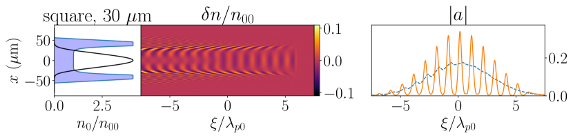
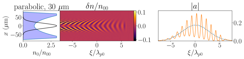
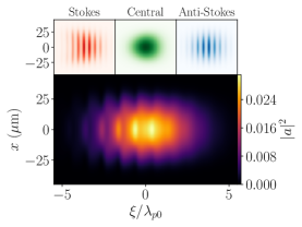
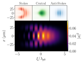
As observed in Fig. 2, Eq. (5) implies that the spectral modulation of the drive pulse is limited by wave-front curvature of the plasma wave. For low amplitude wakes this curvature is dominated by the transverse profile of the plasma channel. For square channels the wake has flat phase fronts over most of the transverse profile of the lowest-order mode of the channel. However, for channels with a curved transverse profile, such as parabolic channels, the wave-fronts of the plasma wave are curved, which can strongly suppress the spectral modulation.
Figure 3 shows the results of 2D PIC simulations that compare the performance of a modulator with square and parabolic plasma channels. It can be seen that for the square channel the wave-fronts of the plasma wave are flat across most of the channel width, and as a consequence the pulse train generated by removal of the sideband spectral phase exhibits strong temporal modulation over the entire duration of the pulse train. In contrast, the wave-fronts of the wake driven in a parabolic channel of matched spot size are strongly curved, and this curvature increases towards the tail of the drive pulse. As a consequence, the generated pulse train does not exhibit complete intensity modulation near its tail, which would reduce the amplitude of the plasma wave it could drive in the accelerator stage. As shown in Fig. 3, increasing the matched spot size of the parabolic channel to reduces the wake curvature, which leads to improved modulation of the generated pulse train. We note that the deleterious effects of wave-front curvature would be even more pronounced in 3D geometry (see Supplemental Material [22]).
III Stability of the Plasma Modulator
It is important to understand the extent to which instabilities will arise in the modulator, and the range of laser and plasma parameters for which any deleterious effects arising from them can be avoided. Since we do not want to waste any of the drive pulse energy within the modulator stage, we would like its envelope to remain smooth as it propagates. Although the specific set of parameters used in the original P-MoPA proposal [12] were shown to work in simulation, for the scheme to be practical we want a large, well-defined parameter space where it is stable.
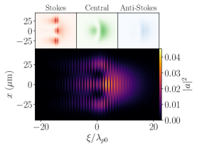
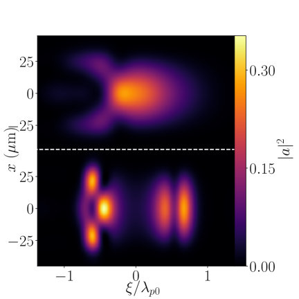
Increasing the drive pulse energy eventually disrupts the plasma modulator with a TMI via a self-modulation mechanism. This instability drives time-varying wakes which excite higher order transverse channel modes. The results of PIC simulations demonstrating this phenomenon are given in Fig. 4. It can be seen that the Stokes sidebands become more defocused towards the trailing end of the pulse, thereby exciting higher order transverse modes, whereas the anti-Stokes-shifted light remains relatively well focused. This asymmetry between the Stokes and anti-Stokes light leads to the formation of low-contrast pulse trains in the modulator, with the Stokes-shifted radiation forming a train off-axis, and the anti-Stokes light forming a train on-axis. This effect becomes worse with increasing drive pulse energy, and can be seen to be especially bad for the pulse, which has undergone severe transverse break-up and has been strongly redshifted. This difference in behaviour between the Stokes and anti-Stokes sidebands has previously been observed as the result of relativistic effects [28]. As shown in the Supplemental material [22], a similar effect is predicted in the non-relativistic regime when non-paraxial effects are accounted for.
III.1 Envelope Self-Modulation and Raman Forward Scattering
We now consider the stability of picosecond-scale pulses propagating in long unperturbed plasma channels, i.e. in the absence of a wake driven by a seed pulse. As discussed by Mori [29], as long as is satisfied, the following parameter determines whether a laser pulse will be dominated by Raman forward scattering (RFS) or envelope self-modulation (SM) instabilities:
| (6) |
where is the peak laser power and is the laser duration. When , RFS dominates, whereas SM dominates when . Substituting laser-plasma parameters used by Jakobsson et al [12], we find and , meaning that we are well in the SM-dominated regime. The maximum growth rate and -folding number of envelope SM in a uniform plasma is given by [30, 31]
| (7) |
where is the interaction time.The parameters used by Jakobsson et al [12] yield -foldings, and hence SM could become problematic, especially if we try to include more energy in the drive pulse.
III.2 Transverse Mode Stability Condition
For a pulse propagating in a waveguide, the growth of SM is complicated by oscillations in the spot size of the mode, which arise from excitation of more than one waveguide mode. This becomes relevant when the SM growth rate is slower than the spot size oscillation frequency [32] . In this section we consider the effects of the plasma channel on self-modulation.
Consider coupling a slightly unmatched drive pulse into a parabolic plasma channel so it undergoes small spot size oscillations, and assume that no centroid oscillations are present, so that only radial Laguerre-Gaussian modes are excited (see Supplemental Material [22]). Neglecting relativistic effects, applying time-dependent perturbation theory to Eq. (II.1), the coefficients of each radial Laguerre-Gaussian mode at longitudinal coordinate are found to evolve according to:
| (8) |
where is the fixed seed wake, is the self-wake of the drive pulse, and and are the spot size and centroid oscillation frequencies respectively [32]. Coupling the drive pulse into a slightly unmatched channel corresponds to following set of initial conditions
| (9) |
where is the channel spot size mismatch parameter. In order to solve Eq. (III.2), the self-wake must be known. We estimate the self-wake as follows. We first assume that the self-wake can be neglected, and calculate the intensity modulation of the drive pulse caused by the seed wake only. We then use this intensity modulation to calculate the self-wake it would excite. This estimate of the self-wake can then be used to define the plasma modulator stability condition, which sets bounds on the laser-plasma parameters to prevent nonlinear self-modulation from exciting transverse mode transitions.
We will work in the shallow channel limit , which allows us to neglect the effects of the channel on wake structure [33]. This gives a seed wake of the form [18]
| (10) |
where and denotes the on-axis seed wake amplitude. As the drive pulse should remain primarily in the fundamental mode, we can approximate Eq. (III.2) as a two-level system comprising the and modes with transitions between them driven by the seed wake
| (11) |
where is the rate of spectral modulation parameter. Note that since we are using the paraxial description, we are implicitly assuming symmetry between the Stokes and anti-Stokes sidebands (see Supplemental Material [22] for the non-paraxial description). We can already see from these expressions that the first radial mode spectrally modulates half as fast as the fundamental, as it is more sensitive to the radial drop-off of the seed wake amplitude . This asymmetry, coupled to spot size oscillations, is one of two effects contributing to plasma-resonant modulations of the drive pulse intensity which excite a self-wake. Since the spot size oscillation frequency is necessarily much higher than the spectral modulation rate, i.e. , as a consequence of the seed wake being small relative to the channel depth parameter, we can integrate Eq. (III.2) by assuming most of the light remains in the fundamental mode to find a first order solution . This yields the following intensity modulation
| (12) |
We see from Eq. (III.2) that the drive pulse is modulated radially, longitudinally, and temporally. This modulation can be physically understood by splitting it into three effects which can be isolated by setting certain terms to zero. The first is a longitudinally uniform spot size oscillation of amplitude , which can be recovered by setting . The second comes from coupling between the spot size oscillations and the seed wake spectral modulation due to the effect mentioned earlier where higher order radial modes spectrally modulate slower than the fundamental mode in the seed wake. The third depends purely on the seed wake, which can be seen when setting . The seed wake introduces local variations in the matched spot size as it perturbs the channel plasma density, varying the spot size longitudinally in and temporally in .
To estimate the self-wake that would be excited by this intensity modulation, we are only interested in keeping terms resonant with the plasma which excite the largest amplitude self-wake. We also only consider propagation times up to , as this provides sufficient spectral modulation for compression into a pulse train which roughly coincides with the minimum modulation required to reach the accelerator stage wake amplitude plateau discussed by Jakobsson et al [12]. With both of these considerations in mind, we can Taylor expand the terms in Eq. (III.2) to first order in . This gives the plasma-resonant part of the intensity modulation and the approximate self-wake it would excite [34]
| (13) |
where indicates the total energy of the drive pulse contained between its head and coordinate . To prevent self-modulation driving transverse mode transitions (and to make this calculation self-consistent), we require that the self-wake effect on the transition must be negligible throughout the full propagation in the modulator, resulting in the constraint
| (14) |
Substituting and Eq. (III.2) into this constraint yields the plasma modulator transverse mode stability condition
| (15) |
This sets a limit on the total energy of the drive pulse for a given plasma density, spot size, laser wavelength, seed wake and channel spot size mismatch. For the laser-plasma parameters used by Jakobsson et al [12], taking and from the PIC simulations therein, the requirement of Eq. (III.2) becomes , which is satisfied. Hence, in this regime we do not expect the self-modulation effects to be debilitating to the plasma modulator. In PIC simulations, we have found that even letting the LHS of Eq. (III.2) go up to remains stable enough for compression into a pulse train despite the excitation of the first radial mode being non-negligible. Figure 5 shows the calculated intensity profiles, , of drive pulses at the exit of the modulator before and after compression into a pulse train (by removing the expected [27] sideband spectral phase of a pulse without TMI (see Supplemental Material [22])) for drive pulses of energy and various pulse durations. It can be seen that, despite the pulse duration varying by a factor of 16, they each undergo the same amount of spot size oscillation driven transitions to higher order transverse modes. This is in agreement with Eq. (III.2), which is independent of the drive pulse duration. As a consequence, for drive pulses of duration 1, 2 and , the transverse structure of the pulse at the end of the modulator is identical. For drive pulses of duration, the structure is also similar, but in this case the pulse duration is only approximately two plasma periods long, and hence the assumption of small bandwidth breaks down. We note also that Fig. 5 shows that in each case the spectrally-modulated drive pulse can still be compressed into a well-defined pulse train suitable for the accelerator stage, despite the transverse structure that it has developed.

For most practical applications, the spot size oscillations will be determined by the mismatch between the transverse amplitude profile of the lowest-order channel mode, and that of the drive pulse at the channel entrance. However, even in the limit of a perfectly matched channel, small spot size oscillations can arise from other sources, such as ponderomotive and relativistic self-focusing [35, 36]. In addition, the term in Eq. (III.2), which comes from the seed wake forming a plasma-resonant variation in matched spot size, ensures that there will always be an upper limit on the drive pulse energy.
There are two ways that excitation of higher order transverse modes can be mitigated, other than ensuring that Eq. (III.2) is satisfied. However, each of these comes at a cost. First, the treatment above assumed propagation in a shallow channel. For deeper channels, i.e. , the self-wake will be partially suppressed by the off-resonant plasma wave, and the difference in spectral modulation rate of the higher-order mode and the fundamental will be decreased due to the radial component of the seed wake. This allows for more energy to propagate in the modulator without transitions to higher order modes. However, channels of this form also suppress the spectral modulation towards the tail of the pulse, as shown in Fig. 3, which is detrimental to pulse compression. Another option would be to use a leaky channel that leaks higher order modes faster than the fundamental mode [37, 38]. However, this approach would have reduced efficiency, since drive pulse energy transferred to higher order modes would be lost.
IV Conclusion
We have derived a full 3D analytic theory of seeded spectral modulation, and have used this to establish the useful operating regime for the modulator stage in the P-MoPA. This model is found to be in very good agreement with those obtained from 2D PIC simulations of the modulator.
The analytic theory leads to several important conclusions. First, the spectral modulation of the drive pulse is independent of radial distance from the axis of the modulator channel. This ensures that, after leaving the modulator, the entire spectrally-modulated pulse can be compressed by a simple optical system that removes the spectral phase accumulated in the modulator. Second, curvature of the seed-pulse-driven plasma waves is shown to reduce the degree of spectral modulation, and hence the modulation of the pulse train that is generated after compression. This finding establishes limits on the shape of the channel used in a P-MoPA modulator.
We also explored limits to the operating parameters of a seeded modulator set by the self-modulation of the drive pulse and excitation of higher-order transverse channel modes. We found that the operation of the modulator is limited by the onset of the transverse mode instability (TMI), similar to the TMI observed in high power fiber laser systems. An analysis of the excitation of higher-order modes allowed the identification of a condition on the energy of the drive pulse, the relative amplitude of oscillations in its spot size, and the relative amplitude of the seed-pulse-driven wake, that must be satisfied for stable operation.
Finally we emphasize that the results presented here show that the modulator in a P-MoPA can exhibit stable operation over a much broader range of operating parameters than considered in the original proposal [12]. This includes operation at higher drive pulse energies, which bodes well for the development of high-repetition-rate, GeV-scale P-MoPAs.
Acknowledgements.
This work was supported by the UK Engineering and Physical Sciences Research Council (EPSRC) (Grant No. EP/V006797/1), the UK Science and Technologies Facilities Council (Grant No. ST/V001655/1]), InnovateUK (Grant No. 10059294), UKRI funding (ARCHER2 Pioneer Projects) and the Ken and Veronica Tregidgo Scholarship in Atomic and Laser Physics. This publication arises from research funded by the John Fell Oxford University Press Research Fund. This work used the ARCHER2 UK National Supercomputing Service (ARCHER2 PR17125) https://www.archer2.ac.uk. This research used the open-source particle-in-cell code WarpX [39] https://github.com/ECP-WarpX/WarpX, primarily funded by the US DOE Exascale Computing Project. Primary WarpX contributors are with LBNL, LLNL, CEA-LIDYL, SLAC, DESY, CERN, and Modern Electron. We acknowledge all WarpX contributors. This research was funded in whole, or in part, by EPSRC and STFC, which are Plan S funders. For the purpose of Open Access, the author has applied a CC BY public copyright licence to any Author Accepted Manuscript version arising from this submission. The input decks used for the PIC simulations presented in this paper are available at http://doi.org/10.5281/zenodo.7734261References
- Tajima and Dawson [1979] T. Tajima and J. M. Dawson, Laser electron accelerator, Phys. Rev. Lett. 43, 267 (1979).
- Strickland and Mourou [1985] D. Strickland and G. Mourou, Compression of amplified chirped optical pulses, Optics Communications 56, 219 (1985).
- Dawson et al. [2012] J. W. Dawson, J. K. Crane, M. J. Messerly, M. A. Prantil, P. H. Pax, A. K. Sridharan, G. S. Allen, D. R. Drachenberg, H. H. Phan, J. E. Heebner, C. A. Ebbers, R. J. Beach, E. P. Hartouni, C. W. Siders, T. M. Spinka, C. P. J. Barty, A. J. Bayramian, L. C. Haefner, F. Albert, W. H. Lowdermilk, A. M. Rubenchik, and R. E. Bonanno, High average power lasers for future particle accelerators, AIP Conference Proceedings 1507, 147 (2012), https://aip.scitation.org/doi/pdf/10.1063/1.4773687 .
- Hidding et al. [2019] B. Hidding, S. Hooker, S. Jamison, B. Muratori, C. Murphy, Z. Najmudin, R. Pattathil, G. Sarri, M. Streeter, C. Welsch, M. Wing, and G. Xia, Plasma wakefield accelerator research 2019–2040: A community-driven uk roadmap compiled by the plasma wakefield accelerator steering committee (pwasc), PWASC (2019).
- Herkommer et al. [2020] C. Herkommer, P. Krötz, R. Jung, S. Klingebiel, C. Wandt, R. Bessing, P. Walch, T. Produit, K. Michel, D. Bauer, R. Kienberger, and T. Metzger, Ultrafast thin-disk multipass amplifier with 720 mJ operating at kilohertz repetition rate for applications in atmospheric research, Opt. Express 28, 30164 (2020).
- Nagel et al. [2021] S. Nagel, B. Metzger, D. Bauer, J. Dominik, T. Gottwald, V. Kuhn, A. Killi, T. Dekorsy, and S.-S. Schad, Thin-disk laser system operating above 10 kW at near fundamental mode beam quality, Opt. Lett. 46, 965 (2021).
- Produit, Thomas et al. [2021] Produit, Thomas, Walch, Pierre, Herkommer, Clemens, Mostajabi, Amirhossein, Moret, Michel, Andral, Ugo, Sunjerga, Antonio, Azadifar, Mohammad, André, Yves-Bernard, Mahieu, Benoît, Haas, Walter, Esmiller, Bruno, Fournier, Gilles, Krötz, Peter, Metzger, Thomas, Michel, Knut, Mysyrowicz, André, Rubinstein, Marcos, Rachidi, Farhad, Kasparian, Jérôme, Wolf, Jean-Pierre, and Houard, Aurélien, The laser lightning rod project, Eur. Phys. J. Appl. Phys. 93, 10504 (2021).
- Paschotta et al. [2001] R. Paschotta, J. Aus der Au, G. Spühler, S. Erhard, A. Giesen, and U. Keller, Passive mode locking of thin-disk lasers: effects of spatial hole burning, Appl. Phys. B 72, 267 (2001).
- Südmeyer et al. [2009] T. Südmeyer, C. Kränkel, C. Baer, O. Heckl, C. Saraceno, M. Golling, R. Peters, K. Petermann, G. Huber, and U. Keller, High-power ultrafast thin disk laser oscillators and their potential for sub-100-femtosecond pulse generation, Appl. Phys. B 97, 281 (2009).
- Baer et al. [2010] C. R. E. Baer, C. Kränkel, C. J. Saraceno, O. H. Heckl, M. Golling, R. Peters, K. Petermann, T. Südmeyer, G. Huber, and U. Keller, Femtosecond thin-disk laser with 141 W of average power, Opt. Lett. 35, 2302 (2010).
- Kaumanns et al. [2021] M. Kaumanns, D. Kormin, T. Nubbemeyer, V. Pervak, and S. Karsch, Spectral broadening of 112 mJ, 1.3 ps pulses at 5 kHz in a LG10 multipass cell with compressibility to 37 fs, Opt. Lett. 46, 929 (2021).
- Jakobsson et al. [2021a] O. Jakobsson, S. M. Hooker, and R. Walczak, Gev-scale accelerators driven by plasma-modulated pulses from kilohertz lasers, Phys. Rev. Lett. 127, 184801 (2021a).
- Eidam et al. [2010] T. Eidam, S. Hanf, E. Seise, T. V. Andersen, T. Gabler, C. Wirth, T. Schreiber, J. Limpert, and A. Tünnermann, Femtosecond fiber CPA system emitting 830 W average output power, Opt. Lett. 35, 94 (2010).
- Eidam et al. [2011] T. Eidam, C. Wirth, C. Jauregui, F. Stutzki, F. Jansen, H.-J. Otto, O. Schmidt, T. Schreiber, J. Limpert, and A. Tünnermann, Experimental observations of the threshold-like onset of mode instabilities in high power fiber amplifiers, Opt. Express 19, 13218 (2011).
- Jauregui et al. [2011] C. Jauregui, T. Eidam, J. Limpert, and A. Tünnermann, Impact of modal interference on the beam quality of high-power fiber amplifiers, Opt. Express 19, 3258 (2011).
- Smith and Smith [2011] A. V. Smith and J. J. Smith, Mode instability in high power fiber amplifiers, Opt. Express 19, 10180 (2011).
- Jauregui et al. [2020] C. Jauregui, C. Stihler, and J. Limpert, Transverse mode instability, Adv. Opt. Photon. 12, 429 (2020).
- Esarey et al. [1993] E. Esarey, P. Sprangle, J. Krall, A. Ting, and G. Joyce, Optically guided laser wake‐field acceleration*, Physics of Fluids B: Plasma Physics 5, 2690 (1993), https://doi.org/10.1063/1.860707 .
- Andreev et al. [1994] N. E. Andreev, L. M. Gorbunov, V. I. Kirsanov, A. A. Pogosova, and R. R. Ramazashvili, The theory of laser self-resonant wake field excitation, Physica Scripta 49, 101 (1994).
- Mora and Antonsen [1997] P. Mora and T. M. Antonsen, Jr., Kinetic modeling of intense, short laser pulses propagating in tenuous plasmas, Physics of Plasmas 4, 217 (1997), https://doi.org/10.1063/1.872134 .
- Zhu et al. [2012] W. Zhu, J. P. Palastro, and T. M. Antonsen, Studies of spectral modification and limitations of the modified paraxial equation in laser wakefield simulations, Physics of Plasmas 19, 033105 (2012), https://doi.org/10.1063/1.3691837 .
- [22] URL_will_be_inserted_by_publisher.
- Esarey et al. [1995] E. Esarey, P. Sprangle, M. Pilloff, and J. Krall, Theory and group velocity of ultrashort, tightly focused laser pulses, J. Opt. Soc. Am. B 12, 1695 (1995).
- Esarey and Leemans [1999] E. Esarey and W. P. Leemans, Nonparaxial propagation of ultrashort laser pulses in plasma channels, Phys. Rev. E 59, 1082 (1999).
- Kurtz and Streifer [1969] C. Kurtz and W. Streifer, Guided waves in inhomogeneous focusing media part i: Formulation, solution for quadratic inhomogeneity, IEEE Transactions on Microwave Theory and Techniques 17, 11 (1969).
- Firth [1977] W. Firth, Propagation of laser beams through inhomogeneous media, Optics Communications 22, 226 (1977).
- Jakobsson et al. [2021b] O. Jakobsson, S. M. Hooker, and R. Walczak, Supplemental material for gev-scale accelerators driven by plasma-modulated pulses from kilohertz lasers, http://link.aps.org/supplemental/10.1103/PhysRevLett.127.184801 (2021b).
- Gibbon [1990] P. Gibbon, The self‐trapping of light waves by beat‐wave excitation., Physics of Fluids B: Plasma Physics 2, 2196 (1990), https://doi.org/10.1063/1.859401 .
- Mori [1997] W. Mori, The physics of the nonlinear optics of plasmas at relativistic intensities for short-pulse lasers, IEEE Journal of Quantum Electronics 33, 1942 (1997).
- Max et al. [1974] C. E. Max, J. Arons, and A. B. Langdon, Self-modulation and self-focusing of electromagnetic waves in plasmas, Phys. Rev. Lett. 33, 209 (1974).
- Esarey et al. [1997] E. Esarey, P. Sprangle, J. Krall, and A. Ting, Self-focusing and guiding of short laser pulses in ionizing gases and plasmas, IEEE Journal of Quantum Electronics 33, 1879 (1997).
- Gonsalves et al. [2010] A. J. Gonsalves, K. Nakamura, C. Lin, J. Osterhoff, S. Shiraishi, C. B. Schroeder, C. G. R. Geddes, C. Tóth, E. Esarey, and W. P. Leemans, Plasma channel diagnostic based on laser centroid oscillations, Physics of Plasmas 17, 056706 (2010), https://doi.org/10.1063/1.3357175 .
- Andreev et al. [1997] N. E. Andreev, L. M. Gorbunov, V. I. Kirsanov, K. Nakajima, and A. Ogata, Structure of the wake field in plasma channels, Physics of Plasmas 4, 1145 (1997), https://doi.org/10.1063/1.872186 .
- Rosenbluth and Liu [1972] M. N. Rosenbluth and C. S. Liu, Excitation of plasma waves by two laser beams, Phys. Rev. Lett. 29, 701 (1972).
- Siegrist [1976] M. Siegrist, Self-focusing in a plasma due to ponderomotive forces and relativistic effects, Optics Communications 16, 402 (1976).
- Brandi et al. [1993] H. S. Brandi, C. Manus, G. Mainfray, T. Lehner, and G. Bonnaud, Relativistic and ponderomotive self‐focusing of a laser beam in a radially inhomogeneous plasma. i. paraxial approximation, Physics of Fluids B: Plasma Physics 5, 3539 (1993), https://doi.org/10.1063/1.860828 .
- Djordjević et al. [2017] B. Z. Djordjević, C. Benedetti, C. B. Schroeder, E. Esarey, and W. P. Leemans, Laser mode control using leaky plasma channels, AIP Conference Proceedings 1812, 040013 (2017), https://aip.scitation.org/doi/pdf/10.1063/1.4975860 .
- Djordjević et al. [2018] B. Z. Djordjević, C. Benedetti, C. B. Schroeder, E. Esarey, and W. P. Leemans, Filtering higher-order laser modes using leaky plasma channels, Physics of Plasmas 25, 013103 (2018), https://doi.org/10.1063/1.5006198 .
- Fedeli et al. [2022] L. Fedeli, A. Huebl, F. Boillod-Cerneux, T. Clark, K. Gott, C. Hillairet, S. Jaure, A. Leblanc, R. Lehe, A. Myers, C. Piechurski, M. Sato, N. Zaim, W. Zhang, J. Vay, and H. Vincenti, Pushing the frontier in the design of laser-based electron accelerators with groundbreaking mesh-refined particle-in-cell simulations on exascale-class supercomputers, in 2022 SC22: International Conference for High Performance Computing, Networking, Storage and Analysis (SC) (SC) (IEEE Computer Society, Los Alamitos, CA, USA, 2022) pp. 25–36.