Parity-check-aided Dynamic SCL-Flip Decoder with A Simplified Flip Metric for Polar Codes
Abstract
Since polar codes were proposed, improving the performance of polar codes at limited code lengths has received significant attention. One of the effective solutions is a series of list flip decoders proposed in recent years. To further enhance performance, we proposed a parity-check-aided dynamic successive cancellation list flip (PC-DSCLF) decoder in this paper. First, we designed a simplified flip metric, and proved by simulations that this simplification hardly affects the error-correction performance of list flip decoders. Subsequently, we optimized the existing allocation scheme for parity check (PC) bits, and then designed the first multi-PC-aided scheme with the dynamic characteristic for list flip decoders. The dynamic characteristic refers to an excellent ability to correct higher-order errors, which is beneficial for error-correction performance improvement. Meantime, the multi-PC-aided scheme to list flip decoders brings more flexible distributed check bits, which can narrow down the range for searching error bits and achieve a more efficient early termination. Simulation results showed that without error-correction performance loss, PC-DSCLF decoder shows up to 51.1% average complexity gain with respect to the state-of-the-art list flip decoder at practical code lengths. Lower average complexity leads to lower average energy consumption and lower average decoding delay.
Index Terms:
Polar code, successive cancellation list flip (SCLF) decoding, dynamic SCLF decoding, parity check, simplified flip metric.I Introduction
The polar codes using the low-complexity successive cancellation (SC) decoding algorithm are the first channel codes that can provably achieve channel capacity with infinite code length [1]. Due to their excellent performance, polar codes have been adopted in the channel coding scheme for control information in the 5G enhanced Mobile Broadband (eMBB) scenario [2]. However, polar codes with SC decoding algorithm has unsatisfactory error-correction performance at limited code lengths. Hence, low-complexity and high-performance polar decoders at limited code lengths have received significant attention.
The SC list (SCL) decoding algorithm [3], [4] and cyclic redundancy check (CRC)-aided SCL (CA-SCL) decoding algorithm [5], [6] are classic improved algorithms based on the SC decoding algorithm. These two improved decoding algorithms adopt a list of multiple candidate paths to improve the error-correction performance of the SC decoding algorithm with a single candidate path. In particular, by using a CRC, the CA-SCL decoder outperforms the SCL decoder in terms of error-correction performance. However, more candidate paths need more computation complexity (energy) and more storage space. To reduce the computation complexity (energy) or decoding delay, scholars have proposed different breakthrough algorithms, such as adaptive SCL decoding [7], log-likelihood ratio (LLR)-based SCL decoding [8], fast simplified SCL decoding [9], and the list-pruning algorithm [10]. However, these algorithms cannot achieve better error-correction performance than the CA-SCL decoder with the same list size.
To further improve the error-correction performance of the CA-SCL decoding algorithm while maintaining the same list size, [11] proposed the SCL bit-flip (SCL-BF) decoding algorithm. This algorithm introduces the concept of bit flip from SC flip (SCFlip) decoding algorithm [12] into the list decoders for the first time. Thus, the algorithm may find the correct path that a failed list decoder discards, by extra decoding attempts with bit flip. Hence, the SCL-BF decoder obtains better error-correction performance than the CA-SCL decoder with the same list size. It is noted the efficiency of the bit flip operation in SCL-BF depends on two points: (1) the flip method and (2) the decision of the flip position. However, in these two points, SCL-BF decoder is very similar to SCFlip decoder (a based-SC decoder with bit flip) [12], so it is not effective enough for list flip decoders with a list of multiple candidate paths. To improve the efficiency of the bit flip operation, [13] and [14] proposed a list decoder with shift-pruning (SCL-SP) and the SCL flip (SCL-Flip) decoder successively. SCL-SP decoder replaces the bit flip strategy of SCL-BF with a more efficiently shifted-pruning strategy. SCL-Flip decoder designs a novel metric based on the posterior probabilities of all candidate paths to filter bad flip positions. Although both of these two algorithms improve the performance of the SCL-BF algorithm to some extent, they are not effective and flexible enough to correct higher-order errors, which will limit the improvement of error-correction performance and increase the number of unnecessary decoding attempts.
Inspired by D-SCFlip (a based-SCFlip decoding algorithm with the dynamic characteristic) in [15], [16] recently designed a new flip metric to correct higher-order errors in the list decoding process, combined with the distributed CRC technology that contributes to early termination, and finally proposed a dynamic successive cancellation list flip (D-SCLF) decoding algorithm. Both D-SCLF decoder and DSCFlip decoder have the dynamic characteristic, which in this paper refers to the excellent ability to correct higher-order errors using only flip metrics. A high-order error in a decoding process indicates that the process cannot output the correct bit sequence by fixing a single error bit. Benefiting from its capability to correct higher-order errors, for the downlink control channel in 5G, D-SCLF decoder with a list size of only four and only three additional attempts can achieve the performance of a CA-SCL decoder with a list size of eight, which leads to an overall memory and average complexity (energy) reduction [16].
In this paper, we proposed a parity-check-aided D-SCLF (PC-DSCLF) decoding algorithm. The contributions of this algorithm are as follows:
Firstly, we replaced the original flip metric of D-SCLF decoder with a simplified flip metric, considering the origin flip metric contains many logarithmic and exponential operations. The simulation results show that the D-SCLF (or PC-DSCLF) decoding algorithm using the new simplified flip metric and the D-SCLF (or PC-DSCLF) decoding algorithm using the original flip metric have similar error correction performance.
Secondly, inspired by [17], we proposed the first multi-PC scheme that has the dynamic characteristic and can apply to the list flip decoders. Different from the multi-PC scheme [17] applied to the SCFlip decoder, we design a more efficient allocation scheme for multi-PC bits and a multi-PC-aided list flip decoding scheme with the dynamic characteristic. On the one hand, the new allocation scheme can eliminate the duplicate function of the last PC bits and CRC bits, and thus make PC bits play a greater role in early termination. On the other hand, the dynamic characteristic enables our scheme to have the same capability to correct high-order errors as D-SCLF decoder. Besides, we extend the original multi-PC bit scheme that only applies to the SCFlip decoder with a single candidate path to the one that can apply to the list flip decoder with a list of multiple candidate paths. These three points are not available in the original multi-PC scheme.
The successful application of the multi-PC scheme to D-SCLF decoding also means that the position and number of the distributed check bits are more flexible, instead of being restricted like the previously distributed CRC bits in D-SCLF decoder. More flexible check bits not only help the D-SCLF decoding algorithm to narrow down the range for searching error bits, but also help to achieve a more efficient early termination. To better verify the effectiveness of our multi-PC scheme, we have done some simulations without distributed CRC bits involved. Simulation results show the D-SCLF algorithm with our multi-PC scheme shows up to 64.1% average complexity gain with respect to the D-SCLF algorithm with undistributed CRC bits, for .
Finally, we combine the simplified flip metric and multi-PC scheme (including the allocation scheme for multi-PC bits and the multi-PC-aided decoding scheme) to propose the PC-DSCLF decoding algorithm. Simulation results show that our PC-SCLF decoding algorithm shows up to 51.1% average complexity gain with respect to the D-SCLF algorithm with distributed CRC, for , which leads to average energy reduction and average decoding delay reduction.
Without loss of generality, we choose the check bit structure consistent with that in [17]. Besides, represents the code length is 512, the number of the information bits is 256, and the number of check bits is 24.
The remainder of the paper is organized as follows. Section II briefly overviews the encoding method and main SCL-based decoding algorithm. Section III describes and analyzes the details of the proposed decoders. In section IV, the simulation results are illustrated and discussed. Finally, some conclusions are highlighted.
II Preliminaries
In this section, we give a brief overview of the encoding method and main SCL-based decoding algorithms, for a polar code of code length , CRC length , information bits length , and code rate . It is noted that the decoding algorithms introduced in this section only use CRC, so their total number of check bits is equal to .
II-A Polar Encoding Method
The polar encoding method [1] is defined as
| (1) |
denotes the encoded vector. refers to the encoding vector, which consists of two subjects: and . consists of all frozen bits. consists of all non-frozen bits. refers to the Kronecker product and . is a bit-reversal permutation matrix.
II-B CA-SCL decoder
The CA-SCL decoder [5],[6] is a well-known polar code decoding algorithm due to its superior performance. The main reason for obtaining excellent performance is the use of multiple candidate paths and a CRC check.
Assume is total number of candidate paths. In CA-SCL decoding, the path metric (PM) was used to measure the reliability of these paths, which can be an be computed by the following equation [8].
| (2) |
where , and refers to the log-likelihood ratio (LLR) value of the bit in the candidate path. represents the value of the bit in the candidate path, and . A candidate path with a larger means the path is more like to be a wrong estimated path.
When decoding the bit and , CA-SCL decoder utilizes a list to reserve all candidate paths. refers to the set consisted of the first non-frozen bits. When decoding the bit and , paths in are expanded to sub-paths, which forms an expanded list . Then, can be achieved by selecting paths with smaller PM from .
After all bits are decoded, CA-SCL decoding algorithm performs CRC on paths in the . If CRC fails, CA-SCL output the candidate path with smallest PM in . If not, CA-SCL decoder output the candidate path with the smallest PM among those candidate paths passing the CRC check.
II-C SCLFlip decoder
To obtain better error-correction performance of CA-SCL decoder, [11] proposed an SCL bit-flip (SCL-BF) decoder, which is the first decoder introducing flip operations to a failed CA-SCL decoding process. A failure CA-SCL decoding process refers to its corresponding CRC fails. Obviously, the key of SCL-BF decoder to improve the error-correction performance are the accuracy of identifying the first error bit and the efficiency of flip operations.
To improve the accuracy of identifying error bits in a failed CA-SCL decoding process, [14] proposed the SCL flip (SCL-Flip) decoder that designs a novel flip metric based on PM. The new metric in [14] be computed by the following equation.
| (3) |
where denotes the flip metric value of the bit, and is a coefficient to compensate for the biased estimation due to the error propagation. A lower means that mistakes are more likely to occur. Because of this, the SCLFlip decoder prioritizes flipping information bits with lower value.
However, a lower does not represent a higher likelihood of the first mistake happening.
II-D D-SCLF decoder
To optimize the flip metric in SCLFlip, [16] proposed D-SCLF decoders inspired by the D-SCFlip decoder in [15]. D-SCLF decoder designs a new flip metric to approximate the probability of occurring in a CA-SCL decoding process. represents the event that the first mistake happened in the bit.
Furthermore, D-SCLF extends the flip metric and dynamically builds a list of flip sets to correct high-order errors in a failed CA-SCL decoding process. The probability that occrurs with the flip set [16] satisfies
| (4) |
and . Therefore, the extended flip metric in [16] can be obtained by the following calculation.
| (5) | ||||
where . is also a compensated coefficient with similar function like . . records all flip indices for the additional decoding attemps, where and is the max number of additional attemps. Meanwhile, is a subset of a dynamic flip set , where has a constant size of but is updated after each failure decoding attempts. consists of the first unfrozen bits.
Similar to SCLFlip decoder, D-SCLF decoder prioritizes flipping information bits set with lower value computed by (5).
III PC-DSCLF Decoder
III-A The Simplification to The Flip Metric in D-SCLF Decoder
Although D-SCLF algorithm designs a flip metric to approximate the probability of the first mistake happening and utilize it to correct high-order errors, the expression, , contained by the flip metric is inconvenient for efficient hardware implementations. Therefore, inspired by the approximation in [18], we replaced the original flip metric with a simplified flip metric in this section.
We default to 0.4, because it is preferable to have a constant value of and the D-SCLF utilizing with outperforms the SCLFlip decoder using [16].
The new flip metric our proposed satisfies
| (6) |
where
| (7) |
is a positive integer. To make (6) easier to understand, we replace with . Specially, satisfies
| (8) |
where is the last element in .
For illustration purpose, Fig. 1 plots the comparison of and , with .
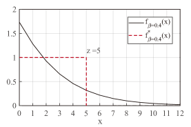
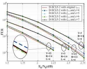
Fig. 2 plots the error-correction performance comparison of D-SCLF-2 decoding algorithm with our approximation against its original approach . D-SCLF-2 refers to the D-SCLF’s number of flip indices for an additional decoding attempt is less than or equal to 2. The reason why we set the maximum number of flip indices for an additional attempt to 2 is to conveniently compare the performance of the D-SCLF decoding algorithm in [16] and to verify the ability to correct high-order errors. In subsequent simulations, we default this value to 2.
We have noticed the frame error rate (FER) performance of D-SCLF-2 decoder using our proposed threshold is similar to that of the origin D-SCLF-2 decoder in general. Particularly, when and (or 7), the FER performance of D-SCLF decoder with outperforms that of the origin D-SCLF decoder. The reason is that the threshold only approximates the probability of incurring the first error.
Therefore, with a similar error-correction performance, our proposed flip metric efficiently eliminates the logarithmic and exponential functions contained by in D-SCLF decoder.
However, with z increases, the FER performance of D-SCLF algorithm with gradually declines when . Therefore, considering a constant value of is preferable and the overall similar error-correction performance is required, we default to 5 in the following sections.
III-B Improved Allocation Scheme for Multi-PC Bits
D-SCLF decoder utilizes the distributed CRC bits to realize early termination and then reduce its computation complexity. However, most of these distributed CRC bits append to the end of non-frozen bits and thus do not contribute to early termination. Besides, other CRC bits that contribute to early termination are also limited in number and location flexibility due to the information bits they protect. Therefore, a more flexible early termination technique that can be applied to D-SCLF decoders is worth exploring.
Inspired by the multi-PC scheme in [17], we infer that if the scheme can be successfully applied to D-SCLF decoding, then a new and more flexible early termination scheme is generated. But there are several difficulties. On the one hand, the original multi-PC scheme can only be applied to SCFlip decoder with a single candidate path and cannot be applied to a more complex list flip decoder with a list of multiple candidate paths. On the other hand, although the original multi-PC scheme adopts a new flip metric to simplify the flip metric in D-SCFlip decoding algorithm, it fails to preserve the dynamic characteristic, which means that it cannot retain the same error correction performance potential as D-SCFlip decoding and will result in redundant decoding attempts. Meantime, although it has a positive effect on the flip efficiency improvement of SCFlip by limiting the flip position in a predetermined set, it may not have the corresponding positive effect when it applies to list flip decoders, because the predetermined set is generated by estimating the first hard-decision error location of SC decoding.
After overcoming these challenges, we propose the first multi-PC scheme that has the dynamic characteristic and can apply to D-SCLF decoding to our knowledge. This scheme consists of an optimized allocation scheme for PC bits and a multi-PC-aided decoding scheme. In this section, we give the details of allocation scheme.
In the original allocation scheme, the PC bits are approximately uniformly distributed on the predetermined set. However, we have noticed the last PC bit and the CRC bits play duplicate roles, due to their close positions. Therefore, we design a new allocation scheme that eliminates this duplicate function to make PC bits play a greater role in early termination.
It is noted that a predetermined set contains more than 99% of all incorrect hard decisions caused by the channel noise in SC decoding process [19]. Meanwhile, a predetermined set consists of only non-frozen bits. For brevity, this paper will not describe the method of generating a predetermined set in detail, and more details are available in fig. 3 of [17].
Assume is the number of elements in the predetermined set, is the number of PC bits, and is the number of CRC bits. Let and . Similar to the allocation scheme in [17], our allocation also includes two cases.
In case one (),
| (9) |
represents the value of non-frozen bit. refers to the index of PC bit in the non-frozen bit sequence . is the index of element in the predetermined set in .
In case two (),
| (10) |
where , and . Then,
| (11) |
where satisfies equation (9) and
| (12) |
To explained our method and its difference from the original method more intuitively, we describe Fig. 3 based a hypothetical non-frozen bit sequence.
Fig. 3 (b) shows our allocation scheme. By simple calculation, we can get . By further calculation according to (9)-(12) ,we can obtain
Similarly, from Fig. 3 (a), we can get
Obviously, the last PC bit and the CRC bits in Fig. 3 (a) play duplicate roles, but no similar situation occurs in Fig. 3 (b). It should be emphasized that although this is a hypothetical non-frozen bit sequence, the reality may be that the last PC bit position coincides with the position of a CRC bit, because the predetermined set is composed of non-frozen bits in , and CRC bits are also in . So this hypothetical non-frozen bit sequence is not an isolated case, and this optimization is necessary.

It is also noted that the main difference between our allocation scheme and the allocation scheme in [17] is that we divide the predetermined set into segments, and the last segment is not protected by a PC bit. Therefore, our proposed scheme can eliminate the duplicate function of the last PC bits and CRC bits, and thus make PC bits play a greater role in early termination.
III-C Multi-PC-aided Decoding Scheme and PC-DSCLF decoder
In this section, we give the details of the PC-DSCLF decoder, which contains the simplified flip metric and a new multi-PC-aided decoding scheme. Unlike the original multi-PC scheme, the new scheme has the dynamic characteristic, which means our scheme can correct high-order errors like D-SCLF decoding. Besides, the successful application of the multi-PC-aided decoding scheme brings more flexible distributed check bits, which can narrow down the range for searching error bits and achieve a more efficient early termination.
Algorithm 1 describes the detail of PC-DSCLF decoder. refers to the maximum of additional attempts. represents the code length. SCLDecoding() denotes standard CA-SCL decoding during which the path selection at the bit indices given in this set is flipped. Specially, SCLDecoding() denotes standard CA-SCL decoding without flip operation. The flip operation refers to the current is achieved by selecting L paths with bigger PM from . refers to the list of flip sets. For example, the flip set records all flip indices for the additional decoding attempt. It is noted is not a subset of , and . and . The initial values of elements in and are both . can be achieved by equation (3).
After SCLDecoding() decoded the bit that is a PC bit, the PC check will be activated. If all paths in cannot pass all PC checks before the bit, PCerr will be updated to 1. Subsequently, the current SCLDecoding() is terminated, and will be updated for use by SCLDecoding(). If not, SCLDecoding() will continue to decoder until the next PC bit. When SCLDecoding() can decoded the bit, the CRC check will be activated. If all paths in cannot pass the CRC check, CRCerr will be updated to 1, and will be updated for use by SCLDecoding(). If not, PC-DSCLF decoding is terminated and outputs the path with the smallest among those candidate paths passing the CRC check in .
Algorithm 2 and Algorithm 3 describe the details of the PC check and the CRC check, respectively. When the current decoding bit is a check bit, one of these checks will be triggered and then updates the value or value.
Algorithm 4 describes the update process of the list of flip sets , which will be triggered only when in Algorithm 1.
If after the initial decoding attempt SCLDecoding(), will consist of indexes of non-frozen bits with smaller , and these non-frozen bits are in .
If after the additional decoding attempt SCLDecoding(), will be updated by inserting new flip sets when ( and ). Besides, a proof is required to ensure that the newly inserted flip set may be executed after the additional attempt. The proof process is as follows.
Proof:
Since and , , which means the proof is completed.
IV Simulation Results and Discussions
To demonstrate the effectiveness of our multi-PC bits scheme, we compare the performance of D-SCLF-2 and PC-DSCLF-2 in Fig. 4 and Fig. 5, with the same and the same number of check bits. Without loss of generality, we choose the check bit structure consistent with that in [17]. The check bits of the D-SCLF-2 algorithm are composed of 8 PC bits and 16 undistributed CRC bits, where the generator polynomial of the 16 CRC bits is . The D-SCLF-2 consists of 24 undistributed CRC bits, and its generator polynomial is . Note that our multi-PC bits allocation scheme is detailed in section III A. Besides, AWGNC channel, BPSK modulation, and Gaussian channel construction algorithm with are used.
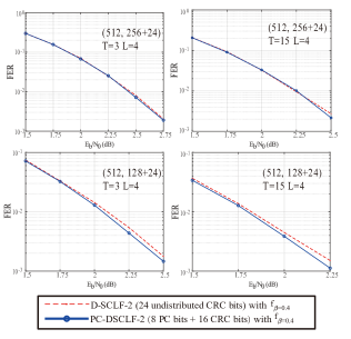
Fig. 4 shows the FER performance of the D-SCLF-2 (24 undistributed CRC bits) and PC-DSCLF-2 (8 PC bits and 16 undistributed CRC bits), with the same and . Under the same code rate, same amount of check bits, same , and same , we observed that the performance curves of the two algorithms almost overlap. Particularly at high , the error correction performance of our algorithm is slightly better than that of D-SCLF-2. The reason is that a longer CRC bit may not contribute to a better error correction performance [20]. This paper does not further investigate the choice of CRC bits since our main goal is to demonstrate that our multi-PC bit scheme does not reduce the error correcting performance of the original method.
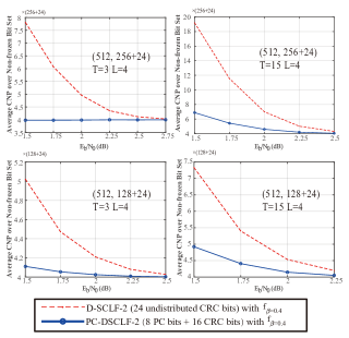
Fig. 5 shows the corresponding average cumulative number of paths (CNP) over of the algorithms in Fig. 4. We utilized the same CNP parameter as [16] to measure the computational complexity since the multi-PC bit technique might lead to an early termination in a decoding process. For an illustration of the computed method of CNP, we give a simple example: for , the CNP in a standard SCL () decoding algorithm is . Simulation in Fig. 5 shows our multiple PC bits scheme adopting shows up to average complexity gain with respect to the D-SCLF-2 algorithm with 24 undistributed CRC bits, without any error-correction performance degradation.
Thus, our multiple PC bits scheme maintains the error-correction performance of the D-SCLF algorithm while reducing its computational complexity.
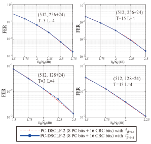
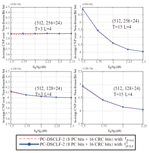
Fig. 6 and Fig. 7 show the FER performance and average CNP of PC-DSCLF-2 algorithm with different flip metrics, respectively. Obviously, the curves of PC-DSCLF-2 decoder with the simplified flip metric and PC-DSCLF-2 with the original flip metric almost overlap. Therefore, our simplified flip metric eliminates the logarithmic and exponential operations in , without increasing average CNP and degrading FER performance.
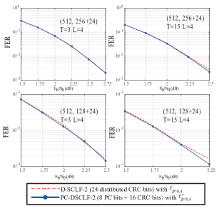
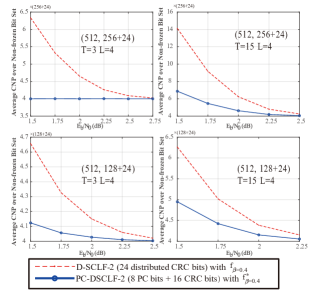
Fig. 8 and Fig. 9 show the FER performance and average CNP of the D-SCLF-2 (24 distributed CRC bits and and PC-DSCLF-2 (8 PC bits and 16 undistributed CRC bits and ), respectively. For the sake of illustration, we define as the CNP of a standard SCL decoding algorithm. As is increased, the average CNP converges to regardless of rate and decoding algorithm. In all cases, our PC-SCLF decoding algorithm converges to quicker than D-SCLF decoding algorithm. Specially, our PC-SCLF (T=15 and L=4) decoding shows up to average CNP gain with respect to the D-SCLF (T=15 and L=4) decoding, for PC(512, 256+24).
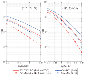
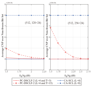
Fig. 10 and Fig. 11 show the FER performance and average CNP of CA-SCL (24 distributed CRC bits) and PC-DSCLF-2 (8 PC bits and 16 undistributed CRC bits), respectively. By only three additional decoding attempts, PC-DSCLF-2 decoder can obtain a similar FER performance with the one of CA-SCL decoder with , while having a similar average CNP with the one of CA-SCL decoder with , for . Although the PC-SCLF decoder further improves FER performance at the cost of computation complexity with the increases, the PC-SCLF decoder with still has a significantly lower computation complexity and a better FER performance than CA-SCL decoder with . Therefore, our PC-DSCLF decoder with low complexity and storage space can achieve the error-correction performance of CA-SCL decoder with a large complexity and storage space, which means PC-DSCLF decoder is an effective low-complexity and high-performance polar decoder.
Based on the above results, we can get: (1) The simplified flip metric designed by the PC-DSCLF reduces the logarithmic and exponential operations in the D-SCLF’s flip metric without sacrificing FER performance and CNP performance. This makes PC-DSCLF decoding more friendly in hardware implementation. (2) Compared to the D-SCLF, our PC-DSCLF with multi-PC-aided scheme greatly reduces its average computation complexity (energy) without FER performance loss, which means our decoder has lower average latency and energy consumption. (3) our PC-DSCLF decoder with low complexity and storage space can achieve the error-correction performance of CA-SCL decoder with a large complexity and storage space. Therefore, PC-DSCLF decoder is an effective low-complexity and high-performance polar decoder.
V Conclusions
In this work, we designed a PC-DSCLF decoding algorithm with a simplified flip metric. On the one hand, PC-DSCLF decoding designed a simplified flip metric, and it was proved by simulations that this simplification hardly affects the error-correction performance. On the other hand, PC-DSCLF decoding proposed the first multi-PC scheme with the dynamic characteristic and introduced it into list flip decoding. The dynamic characteristic gives PC-DSCLF decoding an excellent high-order error correction capability that can reduce the number of redundant decoding attempts. The multi-PC scheme allows PC-DSCLF decoding to locate errors faster and perform early termination more efficiently than the state-of-the-art list flip decoding. Simulation results show that our decoding greatly reduces the computation complexity of the state-of-the-art list flip decoder without loss of error-correction performance. Meanwhile, we also proved through simulations that PC-DSCLF decoding with low complexity and storage space can achieve the error-correction performance of a regular list decoder with a large complexity and storage space. Therefore, PC-DSCLF decoder is an effective low-complexity and high-performance polar decoder.
References
- [1] E. Arikan, “Channel polarization: A method for constructing capacity-achieving codes for symmetric binary-input memoryless channels,” IEEE Transactions on Information Theory, vol. 55, no. 7, pp. 3051–3073, 2009.
- [2] 3GPP, “Nr; multiplexing and channel coding (release 15),” in https://www.3gpp.org/DynaReport/38-series.htm.
- [3] I. Tal and A. Vardy, “List decoding of polar codes,” in 2011 IEEE International Symposium on Information Theory Proceedings, 2011, pp. 1–5.
- [4] K. Chen, K. Niu, and J. Lin, “List successive cancellation decoding of polar codes,” Electronics letters, vol. 48, no. 9, pp. 500–501, 2012.
- [5] I. Tal and A. Vardy, “List decoding of polar codes,” IEEE Transactions on Information Theory, vol. 61, no. 5, pp. 2213–2226, 2015.
- [6] K. Niu and K. Chen, “Crc-aided decoding of polar codes,” IEEE Communications Letters, vol. 16, no. 10, pp. 1668–1671, 2012.
- [7] B. Li, H. Shen, and D. Tse, “An adaptive successive cancellation list decoder for polar codes with cyclic redundancy check,” IEEE communications letters, vol. 16, no. 12, pp. 2044–2047, 2012.
- [8] A. Balatsoukas-Stimming, M. B. Parizi, and A. Burg, “Llr-based successive cancellation list decoding of polar codes,” IEEE Transactions on Signal Processing, vol. 63, no. 19, pp. 5165–5179, 2015.
- [9] G. Sarkis, P. Giard, A. Vardy, C. Thibeault, and W. J. Gross, “Fast list decoders for polar codes,” IEEE Journal on Selected Areas in Communications, vol. 34, no. 2, pp. 318–328, 2015.
- [10] Z. Zhang, L. Zhang, X. Wang, C. Zhong, and H. V. Poor, “A split-reduced successive cancellation list decoder for polar codes,” IEEE Journal on Selected Areas in Communications, vol. 34, no. 2, pp. 292–302, 2015.
- [11] Y. Yongrun, P. Zhiwen, L. Nan, and Y. Xiaohu, “Successive cancellation list bit-flip decoder for polar codes,” in 2018 10th International Conference on Wireless Communications and Signal Processing (WCSP), 2018, pp. 1–6.
- [12] O. Afisiadis, A. Balatsoukas-Stimming, and A. Burg, “A low-complexity improved successive cancellation decoder for polar codes,” in 2014 48th Asilomar Conference on Signals, Systems and Computers. IEEE, 2014, pp. 2116–2120.
- [13] M. Rowshan and E. Viterbo, “Improved list decoding of polar codes by shifted-pruning,” in 2019 IEEE Information Theory Workshop (ITW), 2019, pp. 1–5.
- [14] Y.-H. Pan, C.-H. Wang, and Y.-L. Ueng, “Generalized scl-flip decoding of polar codes,” in GLOBECOM 2020 - 2020 IEEE Global Communications Conference, 2020, pp. 1–6.
- [15] L. Chandesris, V. Savin, and D. Declercq, “Dynamic-scflip decoding of polar codes,” IEEE Transactions on Communications, vol. 66, no. 6, pp. 2333–2345, 2018.
- [16] Y. Shen, A. Balatsoukas-Stimming, X. You, C. Zhang, and A. P. Burg, “Dynamic scl decoder with path-flipping for 5g polar codes,” IEEE Wireless Communications Letters, vol. 11, no. 2, pp. 391–395, 2021.
- [17] B. Dai, C. Gao, Z. Yan, and R. Liu, “Parity check aided sc-flip decoding algorithms for polar codes,” IEEE Transactions on Vehicular Technology, vol. 70, no. 10, pp. 10 359–10 368, 2021.
- [18] F. Ercan, T. Tonnellier, N. Doan, and W. J. Gross, “Simplified dynamic sc-flip polar decoding,” in ICASSP 2020-2020 IEEE International Conference on Acoustics, Speech and Signal Processing (ICASSP). IEEE, 2020, pp. 1733–1737.
- [19] Z. Zhang, K. Qin, L. Zhang, H. Zhang, and G. T. Chen, “Progressive bit-flipping decoding of polar codes over layered critical sets,” in GLOBECOM 2017 - 2017 IEEE Global Communications Conference, 2017, pp. 1–6.
- [20] S. A. Hashemi, C. Condo, F. Ercan, and W. J. Gross, “On the performance of polar codes for 5g embb control channel,” in 2017 51st Asilomar Conference on Signals, Systems, and Computers. IEEE, 2017, pp. 1764–1768.