NEMTO: Neural Environment Matting for
Novel View and Relighting Synthesis of Transparent Objects
Abstract
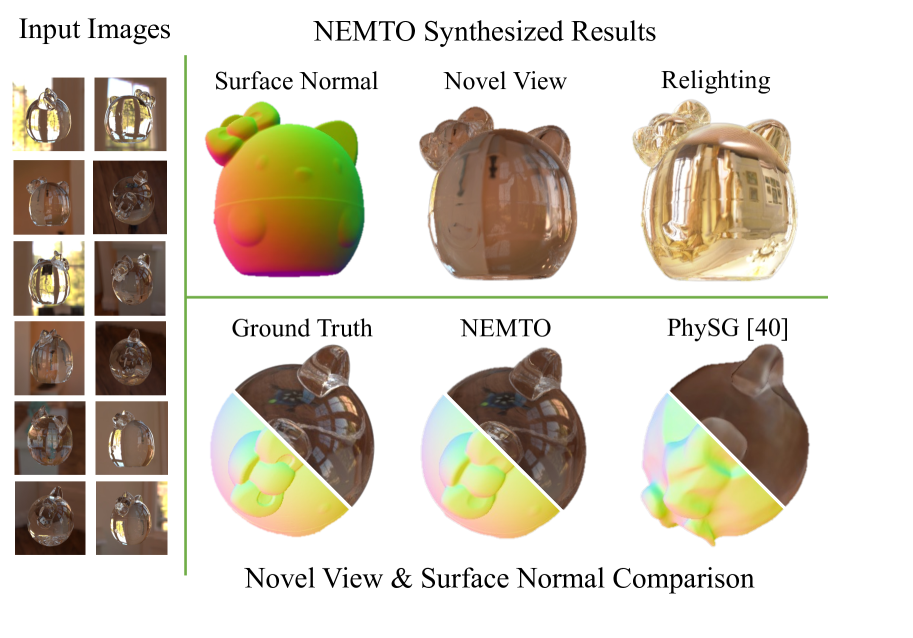
We propose NEMTO, the first end-to-end neural rendering pipeline to model 3D transparent objects with complex geometry and unknown indices of refraction. Commonly used appearance modeling such as the Disney BSDF model cannot accurately address this challenging problem due to the complex light paths bending through refractions and the strong dependency of surface appearance on illumination. With 2D images of the transparent object as input, our method is capable of high-quality novel view and relighting synthesis. We leverage implicit Signed Distance Functions (SDF) to model the object geometry and propose a refraction-aware ray bending network to model the effects of light refraction within the object. Our ray bending network is more tolerant to geometric inaccuracies than traditional physically-based methods for rendering transparent objects. We provide extensive evaluations on both synthetic and real-world datasets to demonstrate our high-quality synthesis and the applicability of our method.
1 Introduction
Modeling transparent objects is important for VR/AR applications as the former are abundant in the real world. Unlike opaque objects with close-to-zero light transmission, transparent objects allow light to pass through. Such refraction and reflection create complex light paths and give transparent objects highly environment-dependent appearances. Consequently, the appearance and geometry of transparent objects are much more entangled than those of opaque objects [27]. A slight error in object geometry can lead to a global change in appearance [37], as the light path for each ray may thus vary substantially. For these reasons, deriving material and object geometry from images of a transparent object is a highly ill-posed and challenging problem.
Existing work for modeling transparent objects can be classified into two categories. One assumes known indices of refraction (IOR) and reconstructs the complex geometry of transparent objects through either physical devices and structured backlights [8, 22, 32, 33, 35, 37] or neural networks that model geometry with analytical refraction [21]. The other [2] focuses on optimizing the refractive ray path in the scene without modeling the object surface geometry. However, neither approach is optimal for synthesizing novel views and relighting for transparent objects with complex geometry. In this work, we propose a new framework that combines recent advances in Neural Inverse Rendering [4, 5, 25, 40, 42, 43] to overcome these limitations.
Traditionally, physically-based rendering follows Snell’s Law to render transparent objects. However, object appearance highly depends on geometry estimation, and jointly optimizing both is highly ill-posed. Therefore, our key contribution is incorporating a physically-guided Ray Bending Network (RBN) to disentangle object geometry and light refraction. RBN takes the learned geometry [39] as prior, and models light refraction by mapping the incoming ray direction directly to the refracted ray direction exiting the object. Our method does not assume a homogeneous refractive index or a fixed number of bounces [2, 27], and models the object’s surface with the zero-level set of the Signed Distance Function (SDF). NEMTO thus has the potential to handle a wider range of complex geometry and better adapt to various refractive media than existing transparent object modeling [2, 21]. Furthermore, our RBN can improve the estimated geometry by better disentangling it from the appearance of the object than other neural rendering methods [39, 40]. NEMTO thus makes it practical to model transparent objects in various scenarios, by working with unknown refractive indices and natural environment illumination. Tab. 1 lists the pros and cons of image-based models on novel view and relight synthesis, along with methods focusing on geometry estimation for transparent objects. We identify the first group as our baseline because the second cannot synthesize views without knowing the object IOR. Experiments show that NEMTO can synthesize higher quality novel views and relighting through our representation of transparent objects than all of our baseline methods.
To summarize, our contributions are as follows111Code and datasets will be made public upon acceptance.:
-
•
We propose NEMTO, the first end-to-end method for novel view synthesis and scene relighting for transparent objects, shown in Fig. 1. Our method can disentangle transparent object geometry and appearance.
-
•
We design a physically-guided Ray Bending Network (RBN) for predicting ray paths traversing through the transparent object. The network prediction has better error tolerance for the estimated geometry than analytically calculated refraction.
-
•
NEMTO can easily be adapted to real-world transparent objects and achieve high-quality image-based synthesis.
2 Related Work
|
|
|
|
|
|
|
|
Task | ||||||||
| NeRF [23] | ✗ | ✓ | ✗ | ✗ | ✓ | ✓ | ✗ | Img-Based Synthesis | ||||||||
| Eikonal [2] | ✓ | ✓ | ✗ | ✗ | ✓ | ✓ | ✗ | |||||||||
| IDR [39] | ✗ | ✓ | ✗ | ✓ | ✓ | ✓ | ✗ | |||||||||
| PhySG, … [40, 43] | ✗ | ✓ | ✓ | ✓ | ✓ | ✗ | ✓ | |||||||||
| NEMTO (Ours) | ✓ | ✓ | ✓ | ✓ | ✓ | ✓ | ✗ |
Geo.
Est. |
||||||||
| [35, 22, 37] | ✓ | ✗ | ✗ | ✓ | ✗ | ✗ | ✗ | |||||||||
| TLG [21] | ✓ | ✗ | ✗ | ✓ | ✓ | ✗ | ✗ |
Neural Rendering. Neural rendering algorithms with implicit scene representation fall into two categories, volume-based and surface-based methods. Volume-based methods, e.g. NeRF [23], enable photo-realistic novel view synthesis by representing the scene as a Multilayer Perceptron (MLP) based radiance field [4, 31, 38]. These methods often cannot distill radiance near the object surface, which is disadvantageous in our case as light refraction strongly relies on ray-surface intersections as prior. Surfaced-based methods [39] directly optimize the underlying geometry with SDFs and estimate object surface with higher accuracy.
Both representations have evolved to model appearance via the rendering equation [17] i.e., to jointly estimate the scene geometry, appearance, and illumination of the scene using existing 2D images [3, 4, 31, 40, 42, 43]. These methods assume that objects have opaque surfaces and light paths are non-refractive throughout the scene, and model appearance with the Disney BRDF model [6, 18]. They provide insights into solving the highly ill-posed inverse rendering problem, but cannot work for transparent objects. In our model, we design an MLP for ray refraction prediction to allow modeling of light through non-opaque objects.
Environment Matting. Environment matting captures the reflection and refraction of environment light by transparent objects. It represents illumination as texture maps and recovers refraction through pixel-texel correspondence. With a structured backlight as background, the light path through the object in the front can be approximately computed [8, 44]. Inspired by traditional environment matting techniques for transparent object shape reconstruction, Chen et al. [7] design a deep learning network to estimate the environment matting as a refractive flow field. These above methods require a controlled dark room to capture images without ambient light. Wexler et al. [33] develop an environment matting algorithm that works with natural scene backgrounds, but that method requires complex camera setups and structured background light. In our method, we approximate environment matting through a neural network. We directly map camera rays to refracted rays and optimize by comparing projected pixels on the environment maps to ground truth pixels. Our method does not require a complex physical setup and is more adaptive to inaccurate geometry.
Transparent Object Modeling. Forward rendering of transparent objects is well-understood given Snell’s Law. Inversely rendering transparent objects and reconstructing the geometry from images, however, remains challenging. Kutulakos et al. [20] first prove that a ray path through two-interface refractive media can be recovered theoretically. Given this insight, previous methods estimating transparent geometry use controlled setups for light path acquisition such as light field probes [32], polarized imagery [13], X-ray CT scanner [28], and transmission imaging [19]. Wu et al. [35] and Lyu et al. [22] use turntables in front of static structured backlights to reconstruct geometry, but our work does not require these special setups. Neural networks are later introduced with analytical refraction modeling to approach the problem. Li et al. [21] assume known environment illumination and IOR to only optimize for geometry with one neural network on all kinds of geometry. Bemana et al. [2] synthesize novel views for transparent objects with unknown IOR, but only work with simple geometry such as a sphere. Our work doesn’t assume known IORs or restrict the light refraction to two bounces. By directly estimating object-specific light refractions, NEMTO synthesizes photo-realistic novel views and relighting for transparent objects on casually-captured images.
3 Method
3.1 Problem Formulation
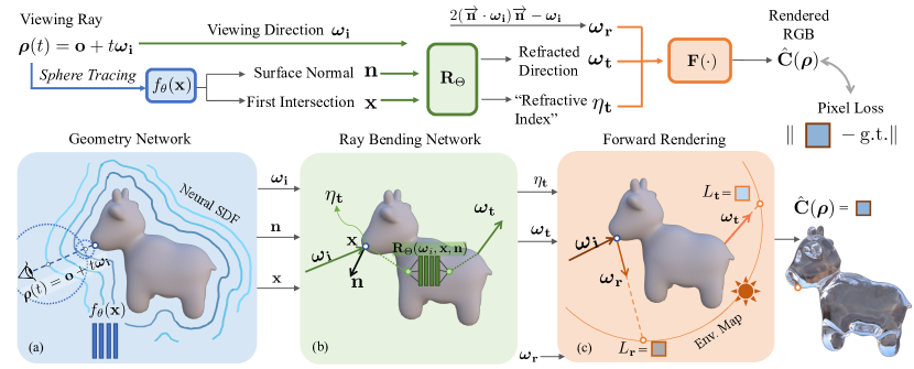
Each input dataset contains multi-view images and object masks of a transparent object with unknown IOR, and an environment map for scene illumination. Object masks and the environment map can be generated by preprocessing image data, which we detail in the supplementary. We assume the images are captured under static distant illumination represented by the environment map. Separately estimating illumination can compensate for entanglement between geometry and lighting, as transparent object appearance is highly correlated to scene illumination. We relax the assumptions that light bounces twice within the transparent media in Li et al. [21] and do not require two reference points on each ray [20]. The model architecture is summarized in Figure 2.
3.2 Geometry Network
We adopt implicit signed distance functions (SDFs) [39] to represent object geometry due to their adaptive resolution and memory efficiency [26]. Specifically, we represent the geometry as a zero-level set of an MLP neural network mapping a 3D location to its SDF value , being its optimizable weights. Concretely, . We optimize geometry with silhouette loss through and regularize the neural SDF with IGR regulariztion [11] for a smooth and realistic object surface, detailed in Sec. 3.5.
To find the intersection point between the viewing ray and implicit geometry surface, we perform ray casting through sphere tracing [12] starting from the intersection between and the bounding box of the object. The surface normal of an SDF at is directly given by its first order derivative: , therefore enabling gradient flow between normal and geometry optimization.
3.3 Ray bending Network
To render each viewing ray through the transparent object in a physically-plausible manner, we design our model to be consistent with the rendering equation [17] and physically-based material model.
Light Refraction and Reflection Modeling. To model a transparent object, one can analytically calculate the light path of an incident ray through the object given the perfect specular reflection and transmission exhibited by its smooth dielectric materials [27]. Specifically, all scattering of radiance for a given ray shares a single outgoing direction.
As shown in Fig. 2. (b), for a 3D point on object surface, we denote the incoming ray direction as , the unit surface normal as , the angle between and as . Likewise denote reflected and transmitted ray direction as and with and . Analytically, , and according to Snell’s Law,
| (1) |
where and are defined as the indices of refraction of the medium through which the incoming and outgoing ray travels, respectively. The analytical reflected ray direction is expressed as:
| (2) |
while the analytical refracted ray direction is formulated as
| (3) |
Neural Environment Matting. The accuracy of the analytically evaluated refracted light direction is highly correlated to the quality of the estimated geometry, which makes it difficult to simultaneously optimize the geometry and light refraction through the object. To overcome this issue, we discard the analytical solution for refraction modeling in Eq. (3) and utilize a neural environment matting method. Our ray bending network (RBN) directly estimates , mapping incident rays intersecting the scene object to the final refracted ray direction, thereby learning how the transparent object refracts environment light and implicitly represents the refractive index through the network.
As shown in Fig. 2 (b), our modeling of light refraction passing through transparent media is expressed as a function , which takes as input the viewing direction , the first intersection point between the viewing ray and the implicit geometry surface, and the surface normal of point . The function output is the refracted direction for the viewing ray exiting the geometry and the “refractive index” at . By incorporating and as priors, we can account for complex viewing effects, such as total internal reflection, which depends on the angle between the surface normal, viewing direction and the concavity of the geometry. We approximate this function using a Multi-Layer Perceptron (MLP) network . To handle high-frequency ray refractions, we apply positional encoding [29] to the viewing direction and surface intersection.
Our light path modeling stems from two important intuitions inspired by traditional environment matting techniques for transparent objects: (1) we assume the scene to contain a single object that is transparent, and we assume the contribution of radiance on each ray segment exiting the object is negligible except for one main refracted ray; (2) the scene illumination will be modeled with an environment map and each ray comes from an infinite distance. From these observations, the final evaluated radiance of each camera ray that intersects with the scene object only depends on its direction upon exiting the object. In the next section, we present our differentiable forward rendering algorithm to work with these assumptions.
3.4 Forward Rendering
The recursive hemispherical integral of the rendering equation for evaluating each viewing ray does not have a closed-form solution and has to be numerically evaluated with the Monte Carlo method [30]. We provide an approximate evaluation of the final radiance as the combination of reflected radiance at incident ray and refracted radiance at outgoing ray through the Fresnel term. Our rendering module is differentiable and designed for physical plausibility.
For transparent objects with smooth surfaces, the view-dependent reflected radiance at each incident point is only dependent on the the reflected ray direction [27, 31]:
| (4) |
while is related to through Eqn. (2). We propose the assumption that an analogous relationship exists between refracted radiance at the incident location and the final refracted ray direction. Specifically,
| (5) |
where maps unit ray direction to a 3-channel RGB color. We reference the RGB value on our estimated environment map by the 2D coordinate obtained through texture mapping from the viewing direction.
We use the Fresnel equation to compute the incident energy split between reflection and transmission, therefore the reflected and transmitted radiance is proportional to the incident ray radiance at the surface intersection. For unpolarized transparent objects, the Fresnel reflectance is given by
| (6) |
| (7) |
where gives the reflectance for parallel polarized light, and is the reflectance for perpendicular polarized light. Since we assume light to be unpolarized, the Fresnel reflectance can be analytically written as,
| (8) |
Due to the conservation of energy, the energy transmittance is therefore given by .
The final radiance for a given ray is then evaluated as:
| (9) |
with denotes element-wise multiplication, and being the IOR for air.
3.5 Optimization
As the joint optimization of geometry and light refraction of transparent objects is highly ill-posed, we enforce different priors to generate visually plausible solutions.
For each batch, we sample the set of all pixels from the input image dataset to get patches, each of neighboring pixels. Therefore a training batch contains pixels we denote as . can be subdivided into two non-overlapping sets of pixels and depending on whether the pixel contains the object or not, . Each is rendered by one camera ray with origin and viewing direction . We apply masked rendering and mask out non-intersecting rays for the loss functions. Specifically, through sphere tracing, if hits the object surface, , otherwise and its rendered radiance .
The Pixel loss for is obtained through the ground truth RGB for and rendered radiance ,
| (10) |
For ray refraction estimation, we use two losses: for each ray that hits the object with viewing direction to guide its refracted direction exiting the object toward the analytical solution obtained by Eq. (3) through cosine similarity,
| (11) |
We employ a weight decaying strategy on to provide initial physically-guided supervision for RBN on refraction. Additionally, we utilize a patch-based loss term for ray hits to encourage locally smooth refraction directions, as we assume that most transparent objects are locally smooth given their smooth dielectric material. For each patch containing only ray hits, we penalize the mean of variance on the estimated refraction directions. Along with , the RBN can better compensate the inaccuracy on estimated geometry than strictly following analytical solution.
For geometry optimization, we employ a silhouette loss from input masks and focus on non-intersecting rays. For each ray , we uniformly sample K points on within the object bounding box and query for the minimal SDF value to penalize on ray miss with the cross-entropy loss with logit parameterized by ,
| (12) |
In order to impose a constraint on the learned function to ensure that it is an approximate SDF, we randomly sample points inside the bounding box and adopt the loss by Implicit Geometric Regularization (IGR) [11]:
| (13) |
The overall loss function of our optimization is defined as the weighted sum of each loss with as weight terms:
| (14) |
4 Experiments
4.1 Synthetic Data Evaluation
Datasets. We use the 4 mesh objects of kitty, cow, bear, and key-mouse from [36, 40], and render each object with the smooth dielectric BSDF model with Mitsuba 3 [16] under an environmental light emitter. For synthetic dataset evaluations we set interior IOR to 1.4723 for glass and exterior IOR to 1.00028 for air. We also create datasets with interior IOR set to 1.2, and 2.4 for ablation studies. We uniformly sample 200 camera poses on the upper hemisphere around each object following the Fibonacci lattice and randomly assign 100 each for training and testing. We obtain object masks through data pre-processing [1].
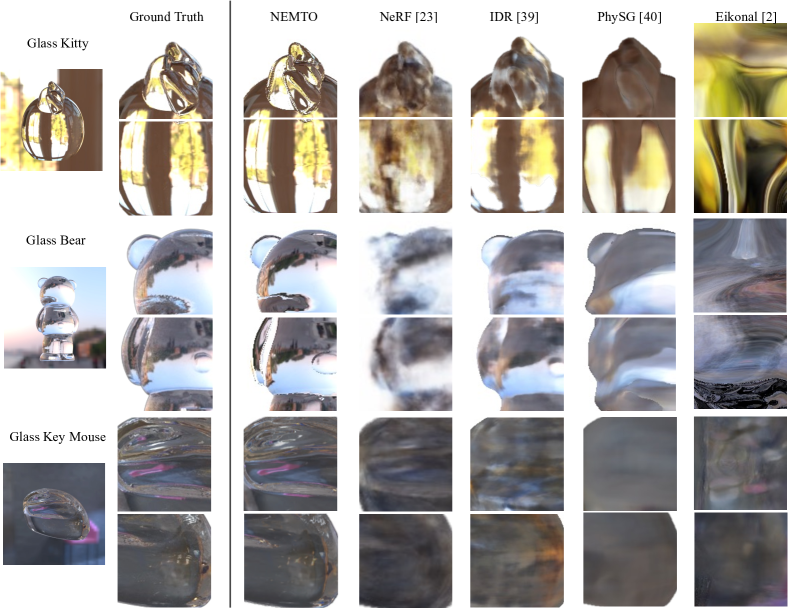
Baseline. As discussed in Sec. 2 and shown in Tab. 1, no other work studies the same problem as ours, i.e., modeling refraction for transparent objects with complex geometry by neural networks for novel view and relighting synthesis. We, therefore, classify our baselines based on different tasks: NeRF [23] and Eikonal Fields [2] on novel view synthesis; IDR [39] on novel view synthesis and geometry reconstruction; PhySG [40] on novel view and relighting synthesis, and geometry reconstruction. As geometry is not our aimed task to improve, extracted mesh quality is only to show that RBN effectively disentangles geometry and ray refraction on appearance. We do not include comparisons with volume-based neural relighting methods [4, 31] as they share the same appearance model with PhySG.
Novel View Synthesis. A qualitative comparison of our method and baseline methods is shown in Fig. 3. NeRF and Eikonal Fields model object appearance as MLP-based volume and cannot distill radiance properly around the object surface. However, when modeling refractive objects with complex geometry, it is important to locate the surface for accurate refraction direction estimation. Eikonal fields relies on user-defined bounding boxes, resulting in failure cases where the opaque scene and the refractive part cannot be separated. Meanwhile, IDR and PhySG are surface-based methods, but IDR models appearance as a light field [34] and cannot correctly interpolate the high-frequency change of the refracted environment illumination on object appearance. PhySG uses Disney BSDF [6] which does not work for non-opaque objects and therefore fails to correctly disentangle geometry and appearance.
We report quantitative evaluation on novel view synthesis with metrics including PSNR, SSIM, and LPIPS [41] through testing on held-out images in Tab. 3. Our method significantly outperforms all of our baselines on synthesizing novel views for accurately modeling the refraction direction of each ray intersected with geometry.
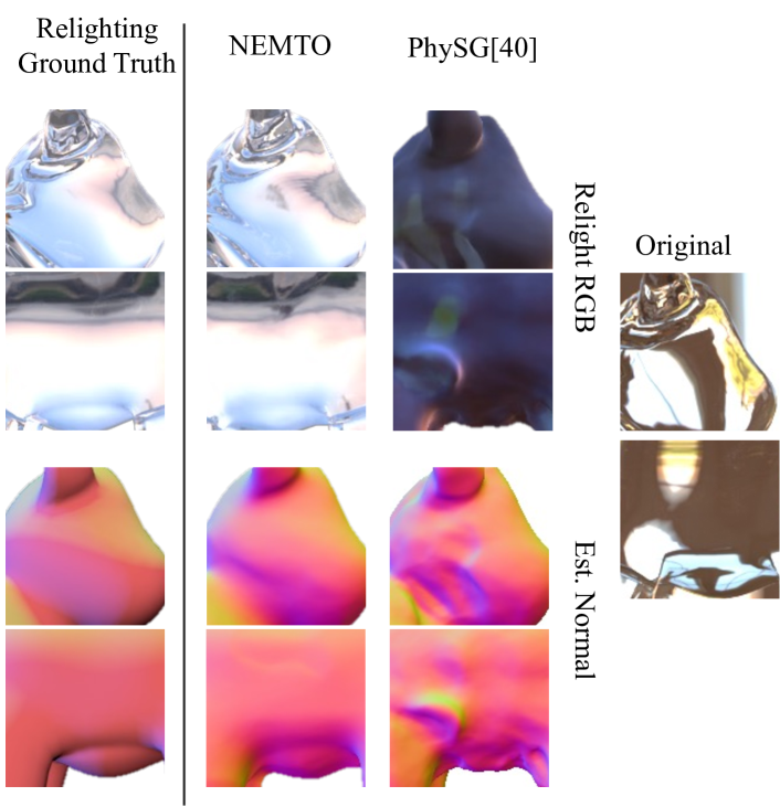
Relight Synthesis. We provide a qualitative comparison of relighting synthesis in Fig. 4. As the environment map used during training is natural and unstructured unlike in prior works [22, 35], many pixels share similar radiance, but our learned refractions are not overfitted on the training illumination; they are aligned with the true refractions. We relight each scene with an unseen environment map to test the correctness of the object refraction. PhySG fails on this task as it does not model refractive material, resulting in incorrect appearance decomposition [6]. We report quantitative evaluation w.r.t ground truth relighting in Tab. 3.
| Synthetic | Chamfer | |||
| Method | Kitty | Bear | Key Mouse | Cow |
| IDR [39] | 4.30 | 3.66 | 3.70 | 11.66 |
| PhySG [40] | 87.67 | 67.43 | 31.61 | 52.17 |
| NEMTO | 2.22 | 1.71 | 2.27 | 2.60 |
Disentanglement on Geometry and Appearance. We evaluate our extracted geometry on synthetic datasets with ground truth mesh through the Chamfer distance metric and compare our geometry with those of surfaced-based methods. In Fig 4, the geometry of PhySG is entangled with surface appearance, i.e. the appearance under the original illumination is imprinted on the surface and raised geometry. Tab. 2 shows that IDR does better than PhySG, though still worse than ours. Our geometry and refracted appearance are better separated due to our modeling of ray refraction and optimizations.
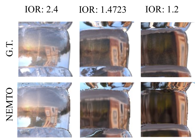
Robustness to different refractive indices. We conducted experiments on transparent objects rendered with various IORs to showcase the robustness of our framework to IOR changes. Our approach is suitable for different types of refractive materials, as demonstrated in Fig. 5. Note that our predicted for the blending of ray refraction and reflection is also adaptive to different IOR, as shown in the case for IOR = 2.4, the reflected radiance is adequately brighter than in IOR = 1.4723 and 1.2.
| Novel View | Relighting | |||||
| Method | PSNR | SSIM | LPIPS | PSNR | SSIM | LPIPS |
| NeRF [23] | 21.274 | 0.837 | 0.171 | - | - | - |
| Eikonal [2] | 15.866 | 0.452 | 0.589 | - | - | - |
| IDR [39] | 22.695 | 0.851 | 0.152 | - | - | - |
| PhySG [40] | 19.981 | 0.791 | 0.203 | 15.412 | 0.749 | 0.237 |
| SDF-A | 21.758 | 0.828 | 0.145 | 17.846 | 0.787 | 0.192 |
| w/o | 15.659 | 0.746 | 0.221 | 14.585 | 0.713 | 0.238 |
| w/o | 21.623 | 0.811 | 0.163 | 19.026 | 0.823 | 0.149 |
| NEMTO | 26.582 | 0.924 | 0.083 | 25.147 | 0.918 | 0.098 |
4.2 Ablation Studies
We perform the following ablation studies to demonstrate the effectiveness of Our RBN, , and .
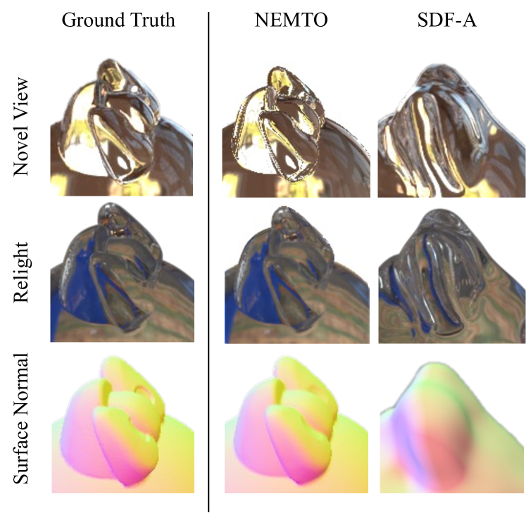
Ablation on ray bending network. We implemented a naive version of our method SDF-A without using RBN. It renders transparent objects with analytical refraction to demonstrates the effectiveness of our RBN and neural environment matting method over the use of a physically-based differentiable renderer on transparent objects. As shown in Fig. 6, our method synthesizes more accurate results when jointly optimizing for geometry and light refraction, which are better disentangled. This is evident from the smoother surfaces of our method due to . NEMTO estimated smoother surface normal than SDF-A, and gives much more faithful ray refractions.
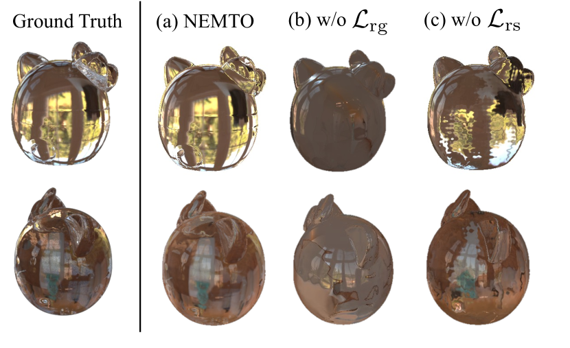
Ablation on and . For experiments on the refraction guiding and refraction smoothness loss, we fix the optimized geometry and only show different optimization results for refraction prediction. The lower part of Tab. 3 shows quantitative evaluation that our complete architecture performs better than without each of these two loss terms. Fig. 8 compares the learned refraction from each ablation experiment: in column (b) without , the model cannot learn the correct direction; in column (c) without , the optimized ray refraction is around the true scope but shows wrong wave-patterned artifacts.
4.3 Real World Data Results
Datasets. For real-world evaluation, we use 4 sets of captured images and environment maps on dog, monkey, pig, and mouse shapes from TLG [21]. As TLG only provides 10-12 images for each real-world object, we render training data with the ground truth CT-scanned meshes following the steps of synthetic datasets generation detailed in the supplementary. We do evaluations on released real-world images.
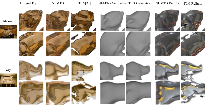
Edited Scene Synthesis. Fig. 7 shows our synthesis for real-world images. Our method is able to predict accurate ray refraction for transparent objects and produces a smoother surface normal prediction on geometry extraction than TLG. TLG designed a novel differentiable rendering layer for physically-based transparent object modeling, but it only renders up to two bounces of refraction, whereas our method does not pose an upper bound on the number of ray bounces. Moreover, TLG does not work with an unknown IOR for transparent objects. Note that, although TLG claims to require only 10-12 images for testing, it requires rendering a large-scale synthetic dataset with 1.5k HDR (High Dynamic Range) environment maps for training, which is unnecessary in our case.
5 Limitations and Conclusion
Limitations. There are a few limitations to our work. First, although NEMTO does not assume homogeneous IOR of transparent media, there is no explicit supervision for heterogeneous transparent objects. With the introduction of appropriate loss functions such as from Eikonal Rendering [15], we believe NEMTO can be extended for a wider variety of transparent media. Secondly, our model requires a preprocessing of image data for environment illumination and object masks, as we cannot jointly optimize illumination along with geometry and object appearance for transparent objects. Lastly, NEMTO focuses on unpolarized transparent objects and does not provide experiments on polarized transparent media [9, 14, 24].
Conclusion. We have presented NEMTO, an end-to-end pipeline for novel view and relighting synthesis of transparent objects with complex geometry. Our method jointly optimizes geometry and highly illumination-dependent object appearance and generates high-quality synthesis.
Acknowledgement. This work was supported in part by the Swiss National Science Foundation via the Sinergia grant CRSII5-180359.
References
- [1] Remove image background., 2022. https://www.remove.bg/. Accessed 2022-11.
- [2] Mojtaba Bemana, Karol Myszkowski, Jeppe Revall Frisvad, Hans-Peter Seidel, and Tobias Ritschel. Eikonal fields for refractive novel-view synthesis. In Special Interest Group on Computer Graphics and Interactive Techniques Conference Proceedings, pages 1–9, 2022.
- [3] Sai Bi, Zexiang Xu, Pratul Srinivasan, Ben Mildenhall, Kalyan Sunkavalli, Miloš Hašan, Yannick Hold-Geoffroy, David Kriegman, and Ravi Ramamoorthi. Neural reflectance fields for appearance acquisition. arXiv preprint arXiv:2008.03824, 2020.
- [4] Mark Boss, Raphael Braun, Varun Jampani, Jonathan T. Barron, Ce Liu, and Hendrik P.A. Lensch. Nerd: Neural reflectance decomposition from image collections. In Proceedings of the IEEE/CVF Conference on International Conference on Computer Vision (ICCV), 2021.
- [5] Mark Boss, Varun Jampani, Raphael Braun, Ce Liu, Jonathan T. Barron, and Hendrik P.A. Lensch. Neural-pil: Neural pre-integrated lighting for reflectance decomposition. In Advances in Neural Information Processing Systems (NeurIPS), 2021.
- [6] Brent Burley and Walt Disney Animation Studios. Physically-based shading at disney. In Transactions on Graphics (Proceedings of SIGGRAPH), volume 2012, pages 1–7. vol. 2012, 2012.
- [7] Guanying Chen, Kai Han, and Kwan-Yee K Wong. Tom-net: Learning transparent object matting from a single image. In Proceedings of the IEEE/CVF Conference on Computer Vision and Pattern Recognition (CVPR), pages 9233–9241, 2018.
- [8] Yung-Yu Chuang, Douglas E Zongker, Joel Hindorff, Brian Curless, David H Salesin, and Richard Szeliski. Environment matting extensions: Towards higher accuracy and real-time capture. In Proceedings of the 27th annual conference on Computer Graphics and Interactive Techniques, pages 121–130, 2000.
- [9] Zhaopeng Cui, Jinwei Gu, Boxin Shi, Ping Tan, and Jan Kautz. Polarimetric multi-view stereo. In Proceedings of the IEEE/CVF Conference on Computer Vision and Pattern Recognition (CVPR), pages 1558–1567, 2017.
- [10] Christian Diller. Chamfer distance for pytorch, 2022. https://github.com/otaheri/chamfer_distance.
- [11] Amos Gropp, Lior Yariv, Niv Haim, Matan Atzmon, and Yaron Lipman. Implicit geometric regularization for learning shapes. arXiv preprint arXiv:2002.10099, 2020.
- [12] John C Hart. Sphere tracing: A geometric method for the antialiased ray tracing of implicit surfaces. The Visual Computer, 12(10):527–545, 1996.
- [13] Cong Phuoc Huynh, Antonio Robles-Kelly, and Edwin Hancock. Shape and refractive index recovery from single-view polarisation images. In Proceedings of the IEEE/CVF Conference on Computer Vision and Pattern Recognition (CVPR), pages 1229–1236. IEEE, 2010.
- [14] Cong Phuoc Huynh, Antonio Robles-Kelly, and Edwin Hancock. Shape and refractive index recovery from single-view polarisation images. In Proceedings of the IEEE/CVF Conference on Computer Vision and Pattern Recognition (CVPR), pages 1229–1236, 2010.
- [15] Ivo Ihrke, Gernot Ziegler, Art Tevs, Christian Theobalt, Marcus Magnor, and Hans-Peter Seidel. Eikonal rendering: Efficient light transport in refractive objects. Transactions on Graphics (Proceedings of SIGGRAPH), 26(3):59–es, 2007.
- [16] Wenzel Jakob, Sébastien Speierer, Nicolas Roussel, Merlin Nimier-David, Delio Vicini, Tizian Zeltner, Baptiste Nicolet, Miguel Crespo, Vincent Leroy, and Ziyi Zhang. Mitsuba 3 renderer, 2022. https://mitsuba-renderer.org.
- [17] James T Kajiya. The rendering equation. In Proceedings of the 13th annual conference on Computer Graphics and Interactive Techniques, pages 143–150, 1986.
- [18] Brian Karis and Epic Games. Real shading in unreal engine 4. Proc. Physically Based Shading Theory Practice, 4(3):1, 2013.
- [19] Jaewon Kim, Ilya Reshetouski, and Abhijeet Ghosh. Acquiring axially-symmetric transparent objects using single-view transmission imaging. In Proceedings of the IEEE/CVF Conference on Computer Vision and Pattern Recognition (CVPR), pages 3559–3567, 2017.
- [20] Kiriakos N Kutulakos and Eron Steger. A theory of refractive and specular 3d shape by light-path triangulation. International Journal of Computer Vision, 76(1):13–29, 2008.
- [21] Zhengqin Li, Yu-Ying Yeh, and Manmohan Chandraker. Through the looking glass: Neural 3d reconstruction of transparent shapes. In Proceedings of the IEEE/CVF Conference on Computer Vision and Pattern Recognition (CVPR), pages 1262–1271, 2020.
- [22] Jiahui Lyu, Bojian Wu, Dani Lischinski, Daniel Cohen-Or, and Hui Huang. Differentiable refraction-tracing for mesh reconstruction of transparent objects. Transactions on Graphics (Proceedings of SIGGRAPH), 39(6):1–13, 2020.
- [23] Ben Mildenhall, Pratul P. Srinivasan, Matthew Tancik, Jonathan T. Barron, Ravi Ramamoorthi, and Ren Ng. Nerf: Representing scenes as neural radiance fields for view synthesis. In Computer Vision–ECCV 2020: 15th European Conference, 23-28 August 2020, Proceeding, 2020.
- [24] D. Miyazaki and K. Ikeuchi. Inverse polarization raytracing: estimating surface shapes of transparent objects. In Proceedings of the IEEE/CVF Conference on Computer Vision and Pattern Recognition (CVPR), volume 2, pages 910–917 vol. 2, 2005.
- [25] Jacob Munkberg, Jon Hasselgren, Tianchang Shen, Jun Gao, Wenzheng Chen, Alex Evans, Thomas Müller, and Sanja Fidler. Extracting triangular 3d models, materials, and lighting from images. In Proceedings of the IEEE/CVF Conference on Computer Vision and Pattern Recognition (CVPR), pages 8280–8290, 2022.
- [26] Jeong Joon Park, Peter Florence, Julian Straub, Richard Newcombe, and Steven Lovegrove. Deepsdf: Learning continuous signed distance functions for shape representation. In Proceedings of the IEEE/CVF Conference on Computer Vision and Pattern Recognition (CVPR), pages 165–174, 2019.
- [27] Matt Pharr, Wenzel Jakob, and Greg Humphreys. Physically based rendering: From theory to implementation. Morgan Kaufmann, 2016.
- [28] Jonathan Dyssel Stets, Alessandro Dal Corso, Jannik Boll Nielsen, Rasmus Ahrenkiel Lyngby, Sebastian Hoppe Nesgaard Jensen, Jakob Wilm, Mads Brix Doest, Carsten Gundlach, Eythor Runar Eiriksson, Knut Conradsen, et al. Scene reassembly after multimodal digitization and pipeline evaluation using photorealistic rendering. Applied Optics, 56(27):7679–7690, 2017.
- [29] Matthew Tancik, Pratul P. Srinivasan, Ben Mildenhall, Sara Fridovich-Keil, Nithin Raghavan, Utkarsh Singhal, Ravi Ramamoorthi, Jonathan T. Barron, and Ren Ng. Fourier features let networks learn high frequency functions in low dimensional domains. NeurIPS, 2020.
- [30] Eric Veach. Robust Monte Carlo methods for light transport simulation. Stanford University, 1998.
- [31] Dor Verbin, Peter Hedman, Ben Mildenhall, Todd Zickler, Jonathan T. Barron, and Pratul P. Srinivasan. Ref-NeRF: Structured view-dependent appearance for neural radiance fields. Proceedings of the IEEE/CVF Conference on Computer Vision and Pattern Recognition (CVPR), 2022.
- [32] Gordon Wetzstein, David Roodnick, Wolfgang Heidrich, and Ramesh Raskar. Refractive shape from light field distortion. In Proceedings of the IEEE/CVF Conference on International Conference on Computer Vision (ICCV), pages 1180–1186. IEEE, 2011.
- [33] Ydo Wexler, Andrew Fitzgibbon, and Andrew Zisserman. Image-based environment matting. In Proceedings, Eurographics Workshop on Rendering, pages 289–299, 2002.
- [34] Daniel N Wood, Daniel I Azuma, Ken Aldinger, Brian Curless, Tom Duchamp, David H Salesin, and Werner Stuetzle. Surface light fields for 3d photography. In Proceedings of the 27th annual conference on Computer Graphics and Interactive Techniques, pages 287–296, 2000.
- [35] Bojian Wu, Yang Zhou, Yiming Qian, Minglun Gong, and Hui Huang. Full 3d reconstruction of transparent objects. arXiv preprint arXiv:1805.03482, 2018.
- [36] Jiankai Xing, Fujun Luan, Ling-Qi Yan, Xuejun Hu, Houde Qian, and Kun Xu. Differentiable rendering using rgbxy derivatives and optimal transport. Transactions on Graphics (Proceedings of SIGGRAPH), 41(6), dec 2022.
- [37] Jiamin Xu, Zihan Zhu, Hujun Bao, and Wewei Xu. A hybrid mesh-neural representation for 3d transparent object reconstruction. arXiv preprint arXiv:2203.12613, 2022.
- [38] Lior Yariv, Jiatao Gu, Yoni Kasten, and Yaron Lipman. Volume rendering of neural implicit surfaces. Advances in Neural Information Processing Systems (NeurIPS), 34:4805–4815, 2021.
- [39] Lior Yariv, Yoni Kasten, Dror Moran, Meirav Galun, Matan Atzmon, Ronen Basri, and Yaron Lipman. Multiview neural surface reconstruction with implicit lighting and material. Advances in Neural Information Processing Systems (NeurIPS), 3, 2020.
- [40] Kai Zhang, Fujun Luan, Qianqian Wang, Kavita Bala, and Noah Snavely. Physg: Inverse rendering with spherical gaussians for physics-based material editing and relighting. In Proceedings of the IEEE/CVF Conference on Computer Vision and Pattern Recognition (CVPR), pages 5453–5462, 2021.
- [41] Richard Zhang, Phillip Isola, Alexei A Efros, Eli Shechtman, and Oliver Wang. The unreasonable effectiveness of deep features as a perceptual metric. In Proceedings of the IEEE/CVF Conference on Computer Vision and Pattern Recognition (CVPR), 2018.
- [42] Xiuming Zhang, Pratul P Srinivasan, Boyang Deng, Paul Debevec, William T Freeman, and Jonathan T Barron. Nerfactor: Neural factorization of shape and reflectance under an unknown illumination. Transactions on Graphics (Proceedings of SIGGRAPH), 40(6):1–18, 2021.
- [43] Yuanqing Zhang, Jiaming Sun, Xingyi He, Huan Fu, Rongfei Jia, and Xiaowei Zhou. Modeling indirect illumination for inverse rendering. In Proceedings of the IEEE/CVF Conference on Computer Vision and Pattern Recognition (CVPR), 2022.
- [44] Douglas E Zongker, Dawn M Werner, Brian Curless, and David H Salesin. Environment matting and compositing. In Proceedings of the 26th annual conference on Computer Graphics and Interactive Techniques, pages 205–214, 1999.