Ultrasound sensing with optical microcavities
Abstract
Nowadays, ultrasound sensors are playing an irreplaceable role in the fields of biomedical imaging and industrial nondestructive inspection. Currently, piezoelectric transducers are the most widely used ultrasound sensors, but their sensitivities drop quickly when the size becomes smaller, leading to a typical sensor size at the millimeter to centimeter scale. In order to realize both high sensitivity and spatial resolution, various optical ultrasound sensors have been developed. Among them, ultrasound sensors using high- optical microcavities have realized unprecedented sensitivities and broad bandwidth and can be mass-produced on a silicon chip. In this review, we introduce ultrasound sensors using three types of optical microcavities, including Fabry-Perot cavities, -phase-shifted Bragg gratings, and whispering gallery mode microcavities. We introduce the sensing mechanisms using optical microcavities and discuss several key parameters for ultrasound sensors. We then review the recent work on ultrasound sensing using these three types of microcavities and their applications in practical detection scenarios, such as photoacoustic imaging, ranging, and particle detection.
I Introduction
The versatility of ultrasound applications has been widely recognized. In industry, flow and level measurement, process control, non-destructive testing of materials, and many other parameters are measured by means of ultrasound [1]. In addition, ultrasound has played an irreplaceable role in biomedical imaging. For example, ultrasound imaging is one of the most commonly used tools for early disease diagnosis due to its low cost, nonionizing radiation, and real-time capability [2, 3]. Ultrasound, which is not affected by the weather, is uniquely suited for applications in the field of transportation where moderate distance accuracy is required, such as reversing radar, object recognition and detection, and automatic obstacle avoidance [4]. These various functions can only be achieved with suitable ultrasound sensors.
Piezoelectric transducers are the most widely used ultrasound sensors in production and clinical [5] applications. The incident acoustic pressure waves deform the piezoelectric material and are measured in terms of the electric potential difference across the piezoelectric material induced by the deformation. This is the piezoelectric effect, which converts ultrasound signals into electrical signals. However, as the piezoelectric transducer achieves higher sensitivity only at resonance, the bandwidth is relatively small and it is difficult to attain high frequencies. In addition, their sensitivities drop quickly when their sizes decrease, leading to a typical sensor size at the millimeter to centimeter scale. Recent rapid advances in micromachining technology have made micro-electro-mechanical systems (MEMS) ultrasound sensors a new option. Capacitive micromachined ultrasound transducers (CMUTs) and piezoelectric micromachined ultrasound transducers allow the integration and miniaturization of ultrasound sensors with increased response bandwidth and sensitivity [6]. Both of these techniques are subjected to electromagnetic interference and the opaque sensor structures make them difficult to achieve multimodal imaging.
In recent years, higher-sensitivity optical ultrasound sensors have become a new direction in the development of ultrasound sensing [7, 8]. Optical ultrasound sensors have experienced a continuous breakthrough in miniaturization from the beginning with free-space optical paths to optical fiber paths and now with the on-chip integration process. Optical ultrasound sensors can be classified as resonance-based or non-resonant-based according to the way they measure [9]. Free space optics generally uses interference to measure ultrasound, such as Michelson interferometers [10], which use the change in optical path caused by ultrasound to measure the interferometric phase change and is a non-resonant-based measurement method. To make ultrasound sensors more portable and practical, optical fibers [11, 12, 13] and waveguide [14, 15] structures have been widely used. In order to further improve the ultrasound sensitivity, optical microcavities [16] are often employed. Ultrasound changes their resonance frequencies by deforming the microcavities, which can be detected by monitoring the reflected or transmitted light intensity of microcavities. Benefiting from the high- optical resonances, unprecedented phase measurement precision can be achieved, which allows ultrahigh ultrasound sensitivity. In addition, microcavities can be massively produced on a silicon chip resulting in a reduced cost, and are generally of microscale sizes allowing high spatial resolution for applications such as photoacoustic tomography. In the past few decades, various ultrasound sensing applications have been demonstrated using multiple types of optical microcavities.
In this review, we present the basics of ultrasound sensing using optical microcavities, including the sensing mechanisms as well as the key parameters of ultrasound sensors. This is necessary to understand the sensing principles and to compare the performance of different sensors. Then, we present influential and relatively new results in this field for three types of microcavities, including Fabry-Perot (F-P) cavities, -phase-shifted Bragg gratings (-BGs) and whispering gallery mode (WGM) microcavities. Their key parameters such as bandwidth and sensitivity are summarized, and their respective advantages and disadvantages are further compared. We also introduce their performance in practical applications. Finally, this review presents a comprehensive comparison of ultrasound sensors based on optical microcavities and further prospects for their future development.
II Ultrasound sensing mechanism
An optical microcavity can be treated as a narrow-band optical filter. The resonance condition is satisfied when the optical path in the cavity is an integer multiple of the wavelength of light.
| (1) |
where represents the effective refractive index and the cavity length, a positive integer number, and the resonance wavelength. The optical field then resonates in the cavity, resulting in a Lorentzian-shaped resonance dip in the transmission spectrum. The linewidth of the dip depends on the optical quality () factor of the cavity mode, which is determined by the optical losses of the cavity. A smaller optical loss gives a higher factor and thus a narrower resonance linewidth . The optical factor can be also expressed as , with and being the resonance angular frequency and the optical decay rate of the mode. A higher optical factor is desirable for sensing, as it provides a higher phase measurement precision. The depth of the dip is determined by the coupling strength of the light and the cavity. For a microcavity, an ultrasonic wave can induce either an optical resonance shift or a change in the coupling strength, both of which will induce a variation in the intracavity optical field and can be optically read out. These two sensing mechanisms through optical resonance shift and coupling strength variation are referred to as dispersive and dissipative sensing mechanisms, respectively. Besides the optical resonances, the optical microcavities also support mechanical resonances. Their response to external stimuli is further improved by a factor of mechanical quality factor , and therefore having a high mechanical factor is also beneficial to achieving a better ultrasound sensitivity. The strong coupling between the optical mode and mechanical mode (i.e., optomechanical coupling) enables ultrasensitive sensing of multiple physical quantities [17, 18]. The mechanical resonance enhanced sensitivity was brought to attention only very recently when high mechanical resonators were developed in the past few years. In the following section, we use a cavity optomechanical system to interpret the physics of the dispersive and dissipative sensing mechanisms.
II.1 Dispersive sensing mechanism
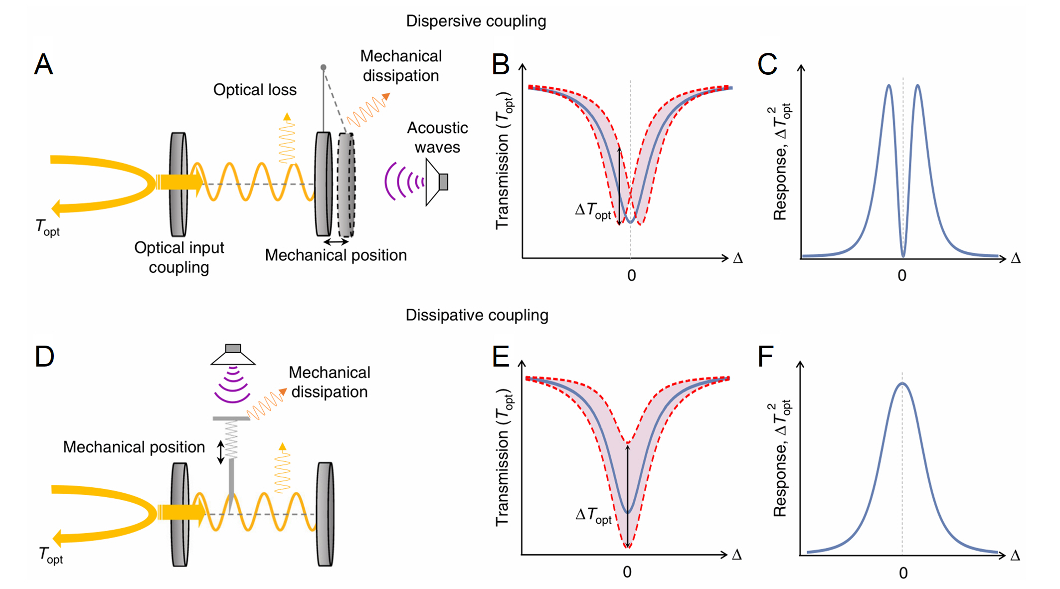
The dispersive sensing mechanism is one of the most commonly used sensing mechanisms for microcavity ultrasound sensing [20]. The principle of the dispersive sensing mechanism is illustrated in Figures 1A-C. A cavity optomechanical system is shown in Figure 1A, in which an optical microcavity is coupled with a mechanical resonator. When ultrasound is incident on a microcavity, the refractive index change due to the photoelastic effect and cavity length variation induced by stress will cause the resonance frequency to shift (Figure 1A). This translates into a periodic modulation of the intracavity optical field at the frequency of the ultrasound. In the measurement, the frequency of the laser is usually locked on the side of the optical resonance to measure the amplitude modulation induced by the ultrasonic wave (Figure 1B). For this measurement method, the optical readout response is proportional to the slope of the transmission, as shown in the response as a function of the optical frequency detuning in Figure 1C. It can be seen that the response reaches the maximum when the frequency detuning . The dispersive sensing mechanism can also also be read out by locking the laser frequency at the center of the optical resonance and measuring the phase modulation. An interferometer is often used to measure the phase modulation [21]. By modifying the two interferometric arms, this method can reduce laser phase noise. The advantage of the dispersive sensing mechanism is that the high optical factor will amplify the optical readout signal. The higher the factor is, the higher the readout sensitivity, and this can be applied to almost all optical microcavity sensors.
II.2 Dissipative coupling mechanism
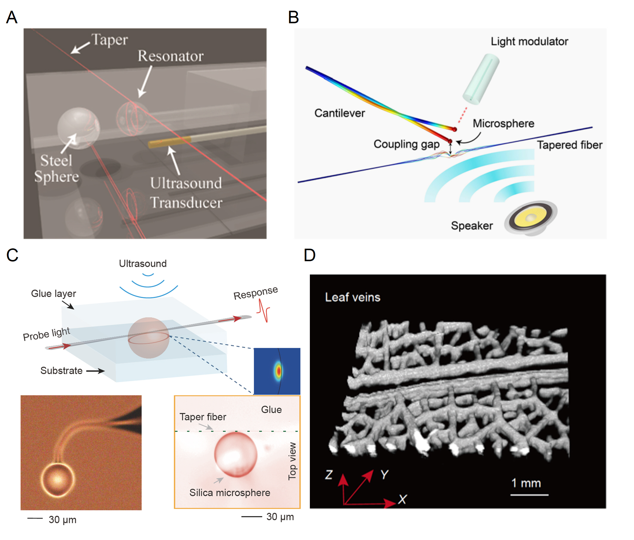
Unlike the dispersive sensing mechanism that measures mode shift, the dissipative sensing mechanism relies on the change in the optical linewidth to read out the ultrasound, as shown in Figures 1D-F. Ultrasound changes the total decay rate by changing the rate of optical coupling into the cavity or the intrinsic loss of the cavity . The variation in the decay rate causes variations in coupling depth (thus the output light intensity) as well as the linewidth. The optical intensity change modulated by the ultrasound can be read out by fixing the incident light frequency at the center of the resonance (Figure 1E). The response reaches the maximum when the detuning and decreases when the detuning increases (Figure 1F). The advantage of the dissipative sensing mechanism is that some optical microcavities are not very susceptible to cavity length changes, and measuring the coupling rate changes between the cavity and the incident light can improve the response to ultrasound. For example, a recent study by Meng et al. [22] found that the perimeter of the microsphere does not change significantly under ultrasound. Instead, owing to the large optical field gradient between the fiber taper and the microsphere, measuring the intensity change through the dissipative coupling can effectively improve the sensitivity.
III Key parameters of ultrasound sensors
There are many parameters to evaluate the performance of ultrasound sensors, such as sensitivity, responsiveness, center frequency, bandwidth, spatial sensing capability, stability, size, etc., and different aspects will be emphasized for comparison in various application requirements. In the following, we focus on the three key parameters of ultrasound sensors, including sensitivity, working frequency and bandwidth, and spatial sensing capability, as they are more commonly used in ultrasound sensing applications.
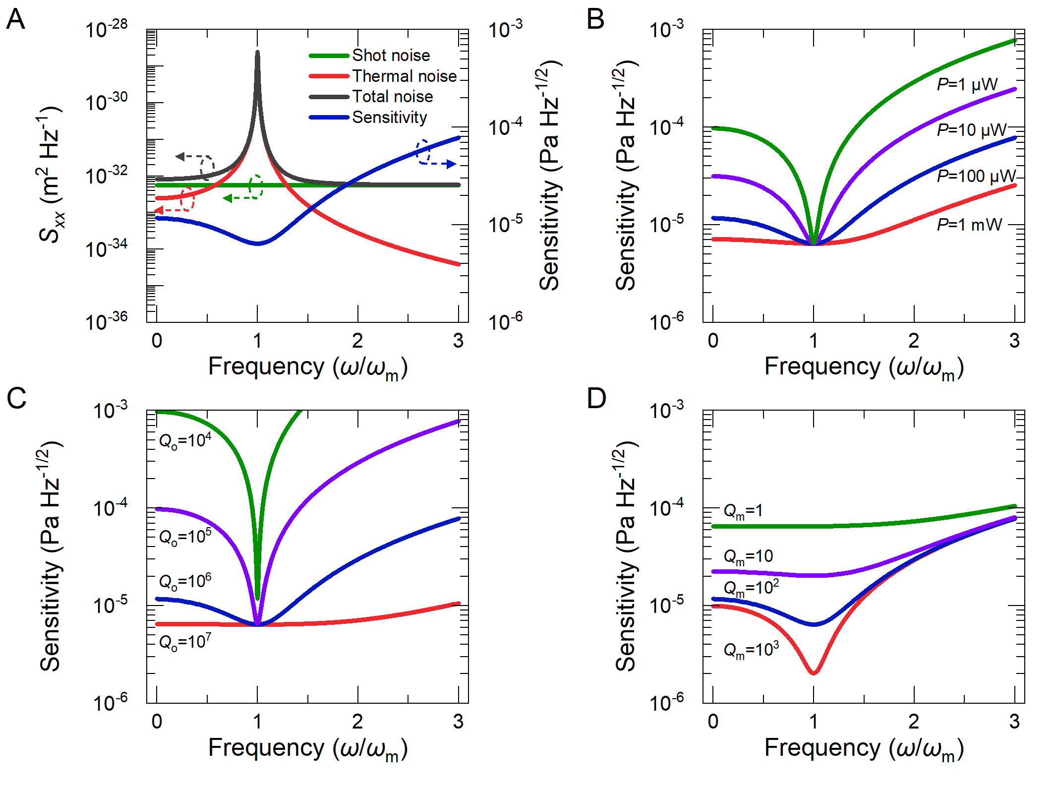
III.1 Sensitivity
Sensitivity is the most important parameter of ultrasound sensors, which is defined as the smallest detectable ultrasound pressure. It characterizes the ability to detect weak ultrasonic waves. Optical ultrasound sensors use light intensity to read out the signal, and the noise equivalent pressure (NEP) is generally used to characterize their sensitivity. NEP is the amplitude of ultrasound pressure that can be read out by the sensor at a signal-to-noise ratio (SNR) of 1. It calibrates the system noise to the effective pressure incident at the sensor surface. The bandwidth of the incident sound pressure is also relevant and NEP (with the unit of Pa) denotes the amplitude of the sound pressure with a certain bandwidth. To characterize the sensitivity of ultrasound sensors within a unit bandwidth, the noise equivalent pressure density (NEPD) can be used, with a unit of Pa Hz-1/2, denoting the NEP for a bandwidth of 1 Hz, corresponding to a measurement time of one second. Increasing the measurement time will decrease the noise floor and therefore improve the NEP. NEP and NEPD, however, are not explicitly differentiated, and in some articles, NEPD is also named NEP.
As mentioned above, the ultrasound sensitivity is ultimately determined by the noise level. For a typical cavity optomechanical sensor, the main sources of noise include the thermal noise related to the environment temperature and the detection noise of the probe laser. The thermal noise mainly comes from the environmental medium damping and the intrinsic loss of the structure, and its displacement noise power spectral density (PSD) is expressed as [23]
| (2) |
() = is the mechanical susceptibility, which quantifies the displacement of the mechanical resonator in response to an external force in the frequency domain, considering a simple case of a single mechanical resonance with a frequency of . is the effective mass and is the damping rate of the mechanical resonator. Decreasing (thus increasing mechanical quality factor ) can enhance the response to near-resonant forces. The detection noise includes the classical technical noise (phase noise and intensity noise) and the quantum shot noise. The technical noise can be significantly suppressed using homodyne or heterodyne detection schemes. As a result, we only consider the shot noise in the following. [18] To better visualize the noise and sensitivity as a function of the frequency, a microdisk optomechanical sensor is utilized as an example. A microdisk with a radius of 100 µm and a thickness of 2 µm has been simulated with a mechanical resonance frequency of 1.3 MHz. The red curve in Figure 2A shows the thermal noise PSD near the mechanical resonance frequency. The temperature is 300 K and the is 100. It can be seen that there is a thermal noise peak near the mechanical mode due to the resonance enhancement, and the response at the mechanical resonance is enhanced by a factor of 100. The displacement PSD of the shot noise is expressed as [24]
| (3) |
In this equation, is the intracavity photon number, where is the incident optical power and is optical resonance frequency. is the optical power decay rate, and stands for the optical detection efficiency. is the optomechanical coupling coefficient, which quantifies how much the optical resonance frequency shift for a mechanical displacement . The shot noise PSD is shown as the green curve in Figure 2A with the optical power µW and optical factor , which is a constant in the frequency range. The shot noise only increases significantly when the frequency is comparable to . The total noise from the sum of thermal noise and shot noise is shown in the black curve in Figure 2A, indicating that the noise is dominated by thermal noise near mechanical resonance frequency and by shot noise when it is far from the mechanical resonance.
By definition, the sensitivity (or NEP) can be obtained from the noise PSD, which is expressed as
| (4) |
where is a coefficient related to the spatial overlap between the ultrasonic wave and the mechanical mode profile of the sensor, and the pressure difference between the upper and lower surfaces of the sensor. is the sensor area. The sensitivity versus frequency is shown in the blue curve in Figure 2A. It can be seen that the sensitivity reaches a minimum at mechanical resonance frequency where the noise is dominated by thermal noise and is degraded in the shot-noise-limited regime. This is due to the fact that mechanical resonance not only enhances thermal noise but also improves response. However, the shot noise is not amplified. Therefore mechanical resonance helps increase the SNR. The fundamental limit of ultrasound sensors is thermal-noise-limited sensitivity. As a result, reaching the thermal-noise-limited sensitivity is essential to achieving high sensitivity for ultrasound sensors.
The thermal noise dominant regime can be reached by optimizing the parameters to reduce the shot noise or increase the thermal noise. From Eq. 4 we can see that increasing the probe power , optical quality factor or the optomechanical coupling coefficient , can reduce the contribution of shot noise. Figures 2B,C show the sensitivity spectra for various incident powers when the is fixed at and for different when the incident power is fixed at 100 µW, respectively. Both incident power and have no effect on the thermal noise term, so the minimum NEP (sensitivity at the mechanical resonance frequency) that can be achieved by the system is constant regardless of how these two parameters are varied. Both Figures 2B,C show that as the incident power and increase, the shot noise decreases, and the frequency range of the thermal noise dominant regime increases, extending the detection bandwidth. It is shown that the sensitivity exhibits a flat spectrum in a frequency range at the order of , for a proper choice of the incident power and the . In addition, as and , increasing the leads to a more effective reduction of the shot noise than increasing the incident power.
Another way to achieve the thermal-noise-dominant regime is to improve the mechanical quality factor . In the one hand, the increase of can not only make it easier for the system to reach the thermal noise dominant regime, but also improve the thermal-noise-limited sensitivity, as shown in Figure 2D. On the other hand, the increase of the will also narrow the linewidth of the mechanical peak, and the thermal-noise-dominated frequency range (i.e., the bandwidth). Due to the high , the thermal-noise-dominated regime can still be reached even when the . Under this premise, a microcavity with lower can realize broadband detection but with compromised sensitivity, and a microcavity with higher can achieve better sensitivity but limited bandwidth in the region dominated by thermal noise. These results show that both optical resonance and mechanical resonance can improve the sensitivity from different aspects. The dual resonance in the cavity optomechanical system enables extremely high sensitivity and has been widely used to measure a broad variety of physical quantities [18].
III.2 Working frequency and bandwidth
All acoustic waves above 20 kHz fall under the category of ultrasound, which has a broad frequency range. Ultrasound with different frequencies has unique applications, so the working frequency and bandwidth of ultrasound sensors are of great interest. For ultrasound imaging, ultrasound of higher frequencies (shorter wavelengths) is desirable as it can provide higher spatial resolution. In order to attain images with micrometer resolution, an ultrasound detector needs to have a center frequency and bandwidth in the MHz range [25]. However, the simple pursuit of high frequencies is not desirable, as sound waves can also be scattered and absorbed in the medium. The absorption loss is proportional to the frequency, and the scattering loss is proportional to the frequency squared. The loss of ultrasonic waves in the air is dominated by the scattering loss, with the attenuation of a 1 MHz frequency ultrasound in the air at the order of 160 dB m-1 [26]. Therefore, balancing between penetration depth and image resolution is necessary. For other applications, the detection bandwidth often determines the performance of the ultrasound sensor. For example, in thermoacoustic and photoacoustic reconstruction, the axial resolution is inversely proportional to the detection bandwidth [27, 28]. An ultrasound sensor of wider bandwidth can detect more details in three dimensions. For another example, most ultrasonic ranging applications employ the time-of-flight (TOF) method, which determines position by reflecting sound waves from the surface of various objects. A larger bandwidth will result in a narrower pulse width in the time domain and therefore better precision. For some specific applications such as sonar and underwater communications, acoustic sensors at kHz frequency are required, to decrease the acoustic loss and therefore expand the detection and communication ranges.
The bandwidths of the traditional piezoelectric transducers are generally at megahertz level, with typical center frequencies at 1-100 MHz and fractional bandwidths (the ratio between the dB or dB bandwidth and the center frequency) of 60–80%. The fractional bandwidth can be increased to over 100% by using capacitive or piezoelectric micromachined ultrasound transducers, but with compromised center frequency generally at a few megahertz levels [29]. For ultrasound sensors with optical microcavities, the bandwidth can be broadened to the level of mechanical resonance frequencies when it is in the thermal-noise-dominant regimes, as discussed above. A bandwidth of up to several hundred megahertz can be achieved using optical ultrasound sensors [30]. For optical resonance-based ultrasound sensors, the intracavity photon lifetime is one of the factors limiting the bandwidth. The lower the optical factor is, the shorter the intracavity photon lifetime is, and the broader the bandwidth is. As a result, there is a tradeoff between sensitivity and bandwidth, regarding the choice of optical factor. In addition, the bandwidth of the sensor is often limited by many other factors, such as mechanical construction, etc. Having a higher mechanical resonance frequency is helpful for achieving a broader bandwidth.
III.3 Spatial sensing capability
The spatial sensing capability of ultrasound sensors includes the ability to respond to ultrasonic waves from different directions (i.e., the acceptance angle), and also the ability to detect ultrasonic waves at different distances. Both of these are significantly influenced by the shape and size of the sensor. Usually, the sensor is most sensitive to the axial ultrasound, and the sensitivity gradually decreases as the angle of incidence increases. Piezoelectric elements are generally directional, typically offering acceptance angles below 20∘ [31], and may require acoustic lenses to increase their acceptance angles. For imaging applications, a wide acceptance angle facilitates more realistic spatial information, in which optical ultrasound sensors are more advantageous. There are various types of optical ultrasound sensors, some of which can achieve an almost full-angle response [32]. In order to minimize ultrasound propagation loss, sensors are frequently placed close to the acoustic sources, but this near-field detection has its drawbacks. Spherical sensors that can be considered as points have a larger acceptance angle but a limited detection distance. While disk or membrane sensors are better suited for long-range detection, their angular response to high-frequency ultrasound is undesirable [33]. Placing the microring detector at the acoustic far field provides a longer working distance and a broader acceptance angle, and the detection at the acoustic near field offers improved sensitivity and broader bandwidth but at the cost of a reduction in the acceptance angle [34].
IV Optical microcavity ultrasound sensors
There are many types of optical microcavities. Depending on the fabrication platform, they can be categorized as free space optical resonant cavities, optical microcavities on fibers, and optical microcavities on a chip. Based on the working principle, they can be classified as F-P cavities, -BGs, WGM microcavities, and photonic crystal microcavities, etc. Some microcavities such as photonic crystal cavities are complex to manufacture and have a relatively low response to ultrasound, therefore are not suitable for ultrasound sensing. This review outlines three types of microcavities that are widely used in ultrasound sensing, namely F-P cavities, -BGs, and WGM microcavities.
IV.1 Fabry-Perot cavities
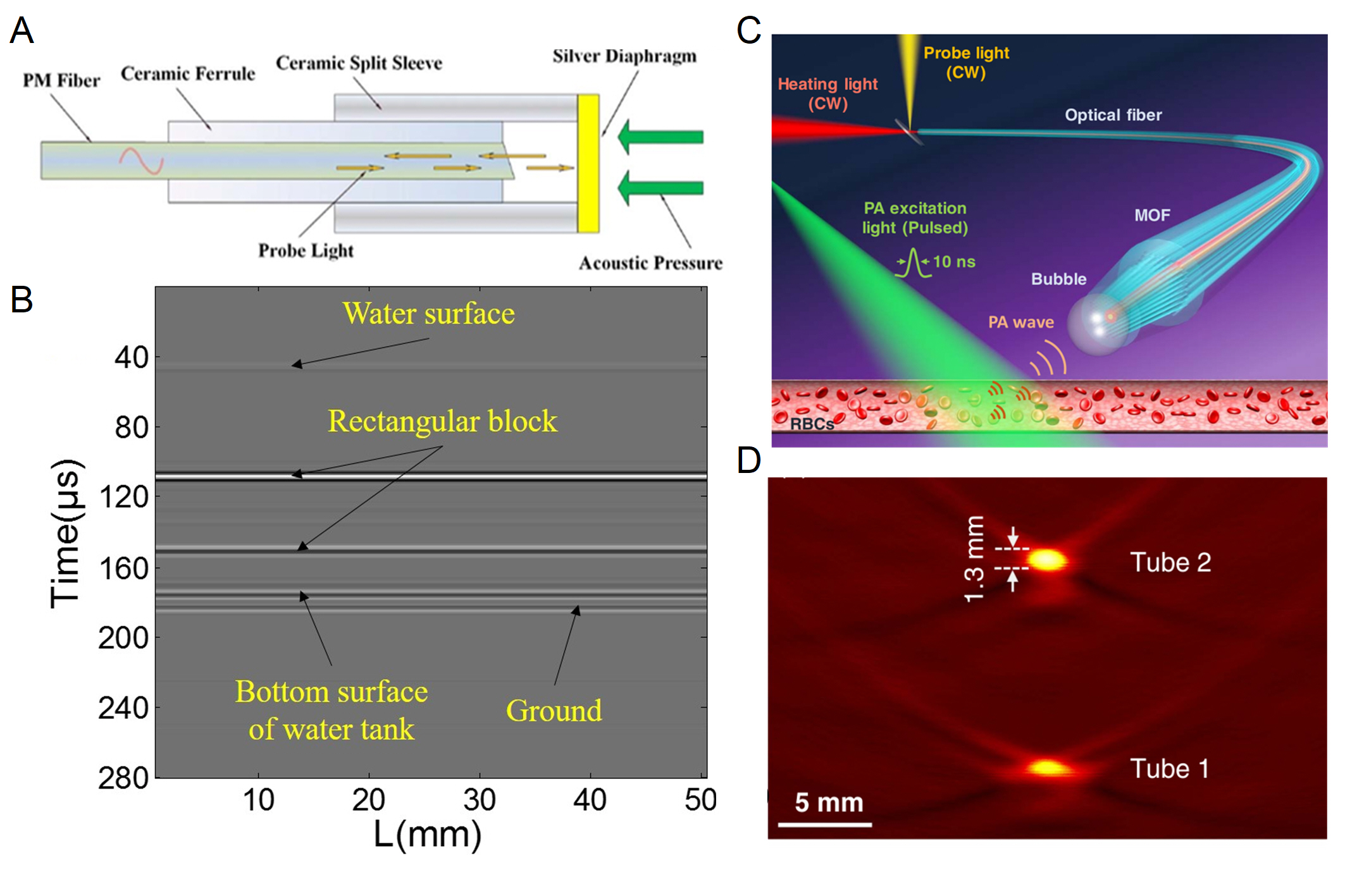
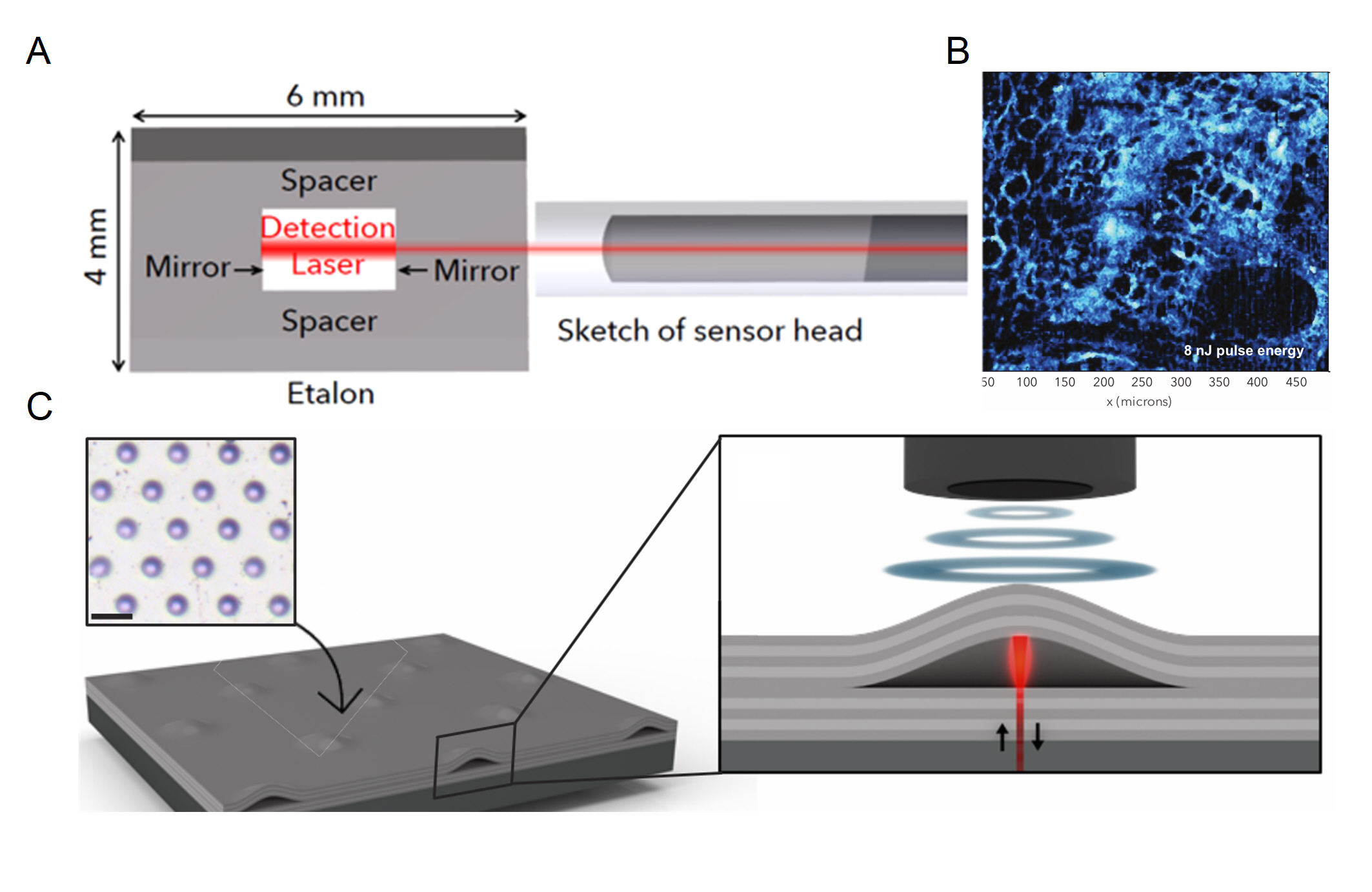
The F-P cavities are the most basic type of optical resonators and have been widely used in many ultrasound sensors [43, 44, 45, 46, 47]. The F-P cavity uses two highly reflective mirrors to localize light in a cavity between the mirrors, which can be realized with the light propagating in the free space or in optical fibers as well as on a chip. F-P cavities for ultrasound sensing are generally not implemented using free-space light, as free-space light paths are generally less mobile and not suitable for most sensing scenarios. Therefore, a majority of ultrasound sensors based on F-P cavities are fabricated at the end of the optical fiber, replacing one mirror with a highly reflective film, which improves both the optical factor and the response to ultrasound [48]. The ultrasound incident on the film causes a change in cavity length and thus modulates the light intensity of the reflected light. In 2013, an F-P cavity using a multilayer graphene film as a reflector was used for ultrasound sensing [49]. Because the film was only 100 nm thick, it realized a NEP of down to 60 µPa Hz-1/2 at 10 kHz and a flat response in the 0.2-22 kHz frequency range. The NEP was then reduced to 14.5 µPa Hz-1/2 by Xu et al. using a silver film with higher reflectivity [35]. Figure 3A shows a schematic diagram of the F-P cavity ultrasound sensor with a silver film. Polymer films with smaller Young’s modulus have also been used to increase the response to ultrasound. Ultrasound sensors made from 353ND [50] and polytetrafluoroethylene (PTFE) [36] films have enabled the TOF method ranging with resolutions of 5 mm and 3.7 mm respectively. Figure 3B shows an ultrasound reconstruction of a Plexiglas block in water using a PTFE diaphragm F-P cavity. A microbubble has also been used for ultrasound sensing as shown in Figure 3C [37]. The microbubble was photothermally generated on a microstructured optical fiber tip, forming a flexible F-P cavity whose gas-water interface was sensitive to ultrasonic waves. This microbubble was capable of detecting weak ultrasounds emitted from red blood cells irradiated by pulsed laser light. Figure 3D shows the reconstructed cross-section photoacoustic image of the blood-filled tubes using this microbubble cavity. To improve the chemical stability of the film and siplify the fabrication process, Fan et al. have made an F-P cavity by splicing three sections of cleaved standard single-mode fibers with the off-core cross-section in the middle [51]. This multi-mode dual-cavity F-P interferometer ultrasound sensor has achieved a broadband ultrasound response from 5 kHz to 45.4 MHz.
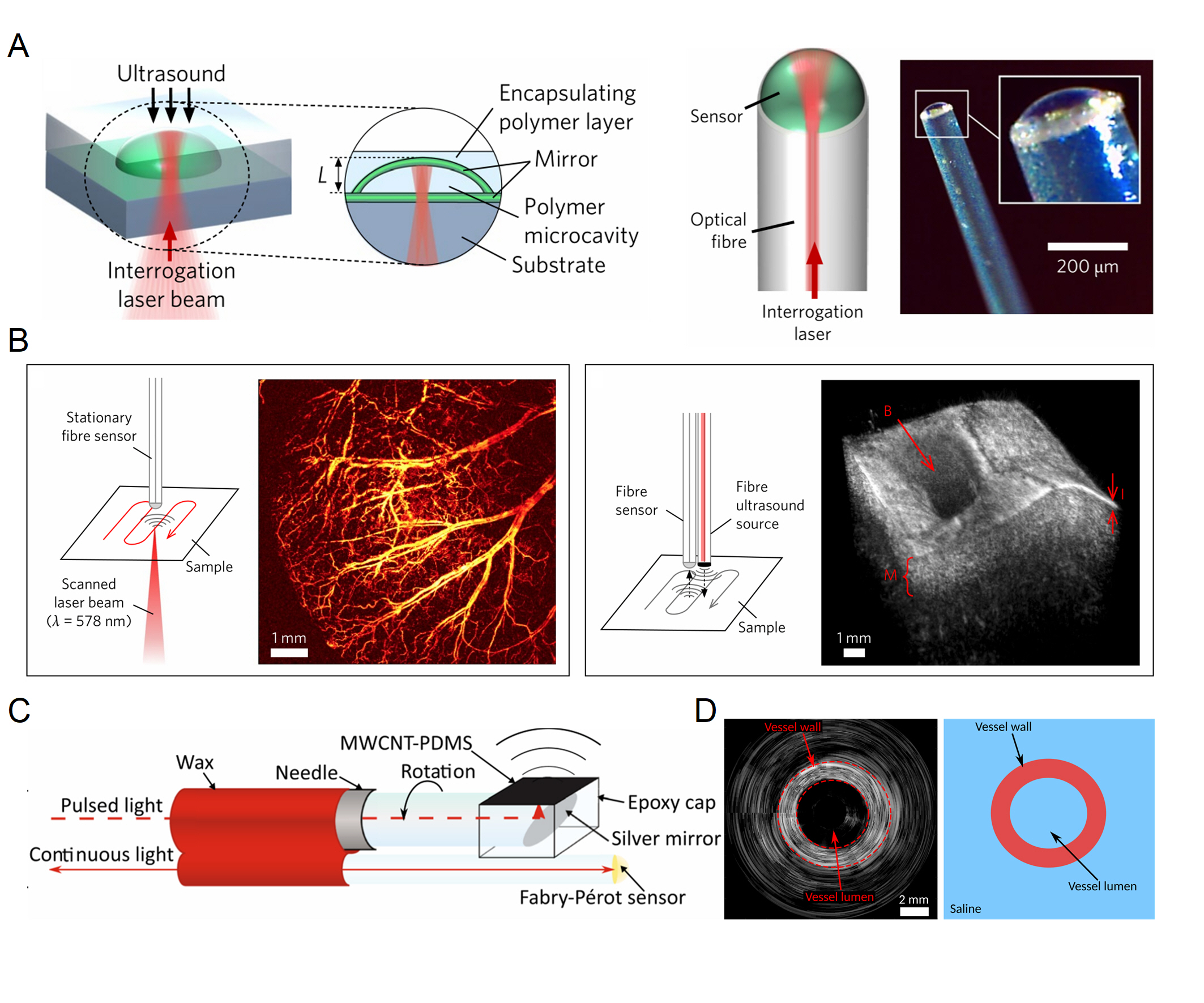
The cavity medium in the previous F-P cavities are air, which is not conducive to encapsulation and is less robust. Therefore in 2017, Guggenheim et al. proposed a flat-concave polymer microresonator that consisted of a solid plano-concave polymer microcavity formed between two highly reflective mirrors as shown in Figure 4A [32]. With a high optical factor of >105, it has realized a broadband response of 40 MHz and a NEP of 1.6 mPa Hz-1/2. This sensor can also be used as a probe for a range of applications, with an almost full angular response when combined on the end face of a fiber (Figure 4A). Figure 4B shows an optical-resolution photoacoustic microscopy image of the mouse ear acquired in vivo (left) and a 3D high-resolution pulse-echo ultrasound image of an ex vivo porcine aorta sample (right) using this ultrasound sensor on a fiber. Another great advantage of the sensor on the fiber is that it can penetrate deep into the tissue for endoscopic imaging. Colchester et al. demonstrated all-optical rotational B-mode pulse-echo ultrasound imaging using an optical head at the distal end with a multi-walled carbon nanotube and polydimethylsiloxane composite coating [38], with its exact structure shown in Figure 4C. The light pulse induces the photoacoustic effect of the coating to produce axial ultrasonic waves, and the F-P cavity next to it is used to receive the tissue echoes, thus enabling compact and minimally invasive probing. Figure 4D shows the rotational optical ultrasound images of an ex vivo swine carotid artery.
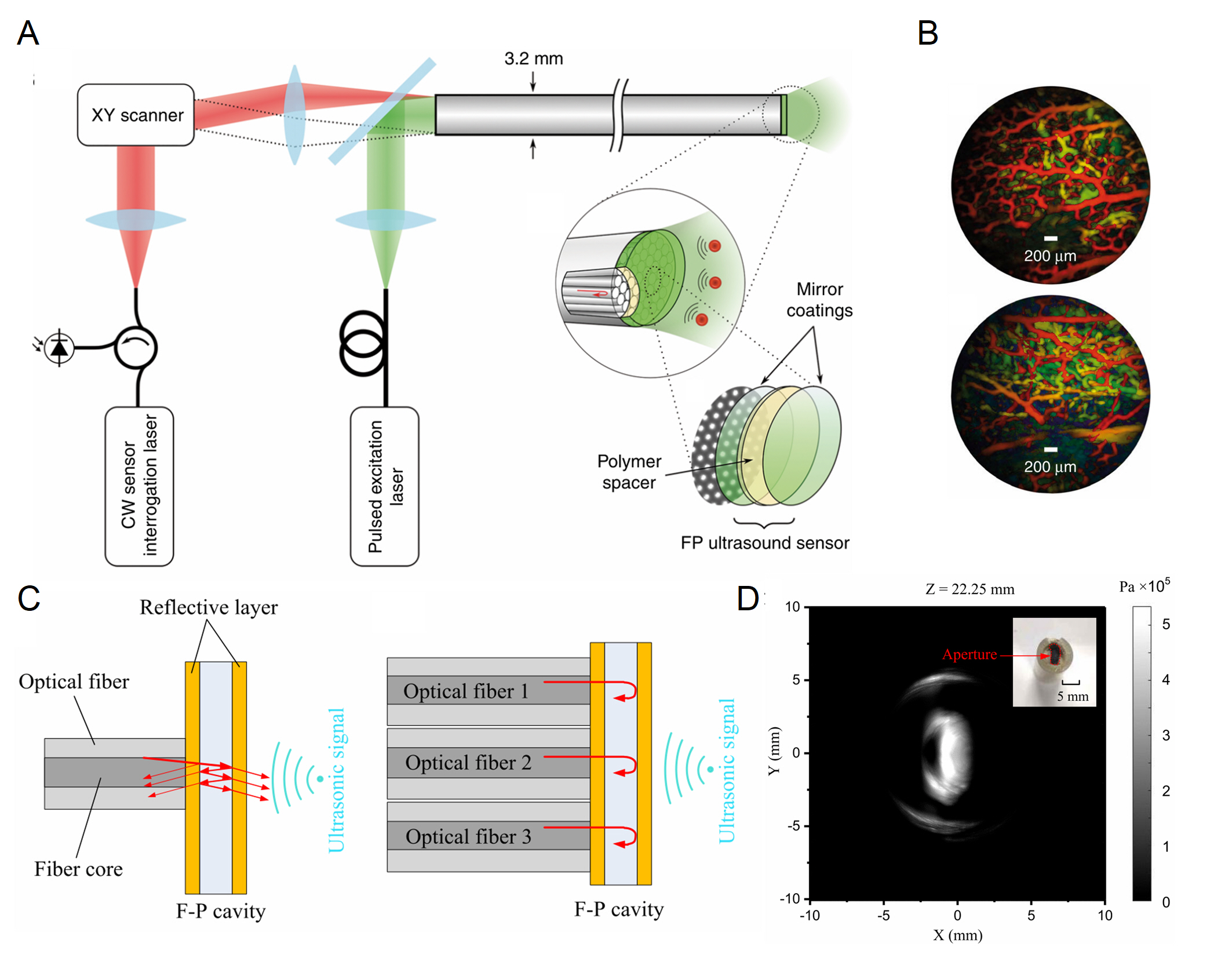
Due to the special cladding-core structure of the fibers, a sensing array can be easily realized using F-P cavities [52]. In 2018, Ansari et al. has realized a forward-viewing endoscopic probe using a 3.2 mm diameter fiber bundle that has 50,000 cores, as shown in Figure 5A [39]. A 15 µm-thick Parylene C film layer between two 90% reflective dielectric mirrors was deposited on the end face of the fiber to form the F-P cavity. Photoacoustic tomography imaging has been realized using this probe. The excitation laser of the photoacoustic signal enters the fiber bundle from all channels, providing a large illuminated field of view. At the same time, the interrogation laser beam is scanned using a lens and coupled into different fiber cores to read out the ultrasound signals at different locations. The lateral resolution of photoacoustic imaging was related to the distance between the cores. The on-axis lateral resolution of the probe was depth-dependent and ranged from 45-170 µm for depths between 1 and 7 mm, and the vertical resolution was 31 µm over the same depth range. Figure 5B shows the photoacoustic images of an ex vivo duck embryo in different regions. However, the drawback of multiple channels is that the optical readout is complicated because the F-P cavities in different channels not necessarily have the same resonant wavelength. In a study by Yang et al., a photothermal tunable fiber optic ultrasound sensor array was demonstrated [53]. The resonant wavelength of each cavity can be controlled by a laser. In 2022, Ma et al. proposed a 416 fiber-optic array based on F-P cavities, which enabled parallel sensing for imaging with a volume rate of 10 Hz [40]. Furthermore, its imaging performance was characterized by reconstructing images from the multichannel signals without mechanical scanning. Figures 5C,D show the principle of parallel sensing and the ultrasound imaging results of an arbitrary-shape ultrasound transducer.
In 2016, Preisser et al. demonstrated a novel all-optical akinetic ultrasound sensor, consisting of a rigid fiber-coupled F-P etalon with a transparent central opening [41]. Unlike other ultrasound sensors based on F-P cavities that use the displacement of the cavity mirror for ultrasound sensing, it uses the change in refractive index within the fluid-filled cavity. The sensor not only achieved a broadband resonance-free flat response in the 22.5 MHz range but also achieved a sensitivity of 450 µPa Hz-1/2 and was used in photoacoustic imaging of biological samples as shown in Figures 6A,B. In addition to being integrated on optical fibers, F-P cavities can also be integrated on a chip. Recently, Hornig et al. realized ultrasound sensing using a monolithic buckled-dome cavity (Figure 6C), with a NEP as low as 30-100 µPa Hz-1/2 in the frequency range below 5 MHz [42]. Due to the sensitive response of the buckled film to external forces, this device has achieved thermal-noise-limited sensitivity.
IV.2 -phase-shifted Bragg gratings
The Bragg grating is a structure with a periodic refractive index. When the Bragg condition is satisfied, there is a high reflectivity in a very small frequency range. The Bragg condition is
| (5) |
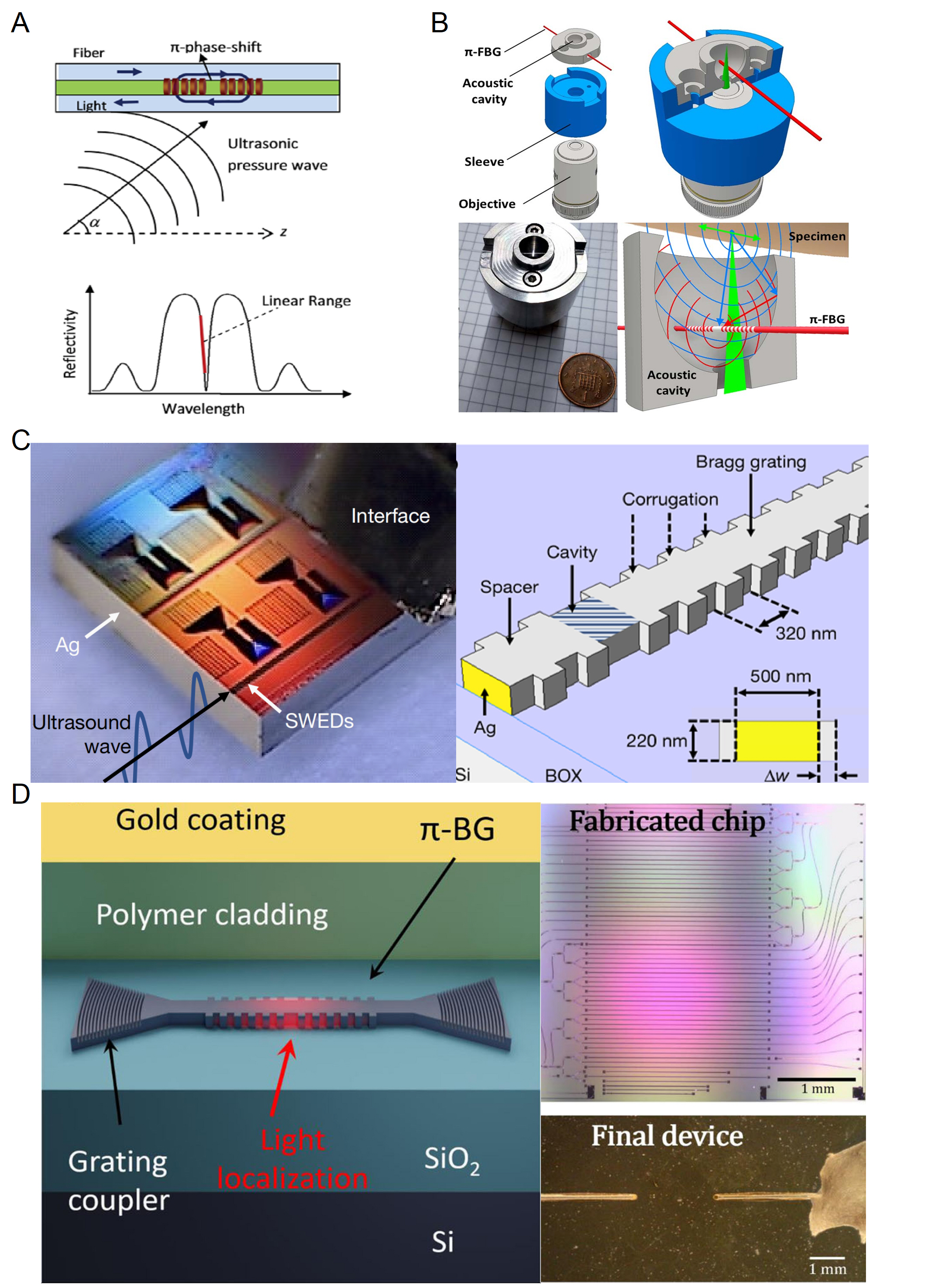
where is the incident light wavelength, is the effective refractive index of the Bragg grating and is the grating period. When an acoustic wave is applied on a Bragg grating, it changes its effective refractive index and period, leading to a change in the reflectivity of the Bragg grating [58]. However, this approach is the result of interference and does not take advantage of optical resonance. Additionally, only ultrasonic waves with wavelengths longer than the grating length can be accurately detected due to the non-uniformity of ultrasonic waves on the Bragg grating disturbance [59]. So researchers introduce a mutation of the phase in the center of the Bragg grating to make -phase-shifted Bragg gratings (-BGs). As a consequence of this phase jump, the grating acts as a highly reflective mirror forming an F-P cavity-like structure in the Bragg grating. Figure 7A shows a schematic diagram of a -BG ultrasound sensor and its reflection spectrum [54]. The formation of the resonator introduces a sharp change at the center of the reflection spectrum (denoted in the red line in the reflectivity spectrum in Figure 7A), which significantly enhances the optical response to ultrasound while reducing the sensing area. In 2011, a -phase-shifted fiber Bragg grating (-FBG) with a reflectivity of over 90% was used for ultrasound sensing, which has realized a detection range of 10 MHz and a NEP of 440 Pa [15]. They used a continuous-wave laser to monitor the shift in resonance wavelengths, a method that was influenced by laser noise. To improve the sensitivity of the optical readout, Riobó et al. measured the phase change near the resonance using a balanced Mach-Zendel interferometer [21]. The interferometric optical path adjustment allowed the phase noise of the laser to be canceled out, achieving 24 times higher SNR than conventional intensity measurement methods.
Due to the chip integration capability, there is great potential for -BGs to be employed in bio-imaging. In 2016, Wissmeyer et al. demonstrated all-optical photoacoustic microscopy using a -FBG. Photoacoustic images of a mouse ear and a zebrafish larva ex vivo have been attained with the optical resolution [60]. Benefitting from the high optical focusing capability and the wide bandwidth ultrasound inspection capability of the -FBG, they achieved a lateral resolution of 2.2 µm and an axial resolution of 10.9 µm. -FBGs can also be well combined with optical microscopy to achieve multi-mode imaging. Figure 7B shows a -FBG and an acoustic resonant cavity compactly combined to increase the ultrasound response while allowing convenient integration into any optical microscope. Shnaiderman et al. used this system to achieve the first in vivo sample measurements in epi-illumination mode with entirely optical hybrid optical and optoacoustic microscopy [55].
-BG can be implemented not only in optical fibers but also in chip-integrated waveguides, which is -phase-shifted waveguide Bragg grating (-WBG). Shnaiderman et al. has taken advantage of the miniaturization of on-chip integration by compressing the sensing area to 200 nm500 nm and implementing an array of eight sensors [56]. Figure 7C shows the details of their structures. This sensor has realized a sensitivity of 9 mPa Hz-1/2 and a wide bandwidth reaching 230 MHz. Such excellent performance has allowed imaging of features 50 times smaller than the wavelength of ultrasound detected, which has enabled ultrasound imaging at a resolution comparable to that achieved with optical microscopy. A further improvement to the -WBG was made by Hazan et al. in 2022, by coating the grating surface with an elastic medium to eliminate the parasitic effect of surface acoustic waves, as shown in Figure 7D [57]. This sensor has realized a sensitivity of 2.2 mPa Hz-1/2 and a bandwidth of up to 200 MHz. The detector was also demonstrated in vivo for high-resolution optoacoustic tomography using an array of -FBGs.
IV.3 Whispering gallery mode microcavities
WGM was first studied in acoustic waves when Lord Reighley found that he could hear two people whispering even if they were very far away. This is because sound waves can be continuously reflected along the curved wall with very small propagation loss. The concept of WGM was then extended to microwaves and optical waves. Analogous to sound waves, light waves can be confined inside a closed circular high-refractive-index dielectric structure through total internal reflection. When the optical path is equal to an integer number times the optical wavelength, the resonance condition is satisfied. With the development of microfabrication technologies in the past few decades, WGM microcavities with extremely high optical factors have been realized [61, 62, 63, 64]. With their high optical factor, small mode volume, and flexible material systems and shapes, WGM microcavities have been demonstrated in various sensing applications [65, 66, 67, 68, 69, 70, 71, 72, 73, 74, 75, 76, 77, 78, 79, 80, 81, 82, 83, 84, 85, 86]. In recent years, WGM microcavities have also been used for ultrasound sensing. In the following, we present the recent ultrasound sensing works using WGM microcavities with different geometries, including microrings, microspeheres, microbubbles, microdisks, and microtoroids.
IV.3.1 Microrings
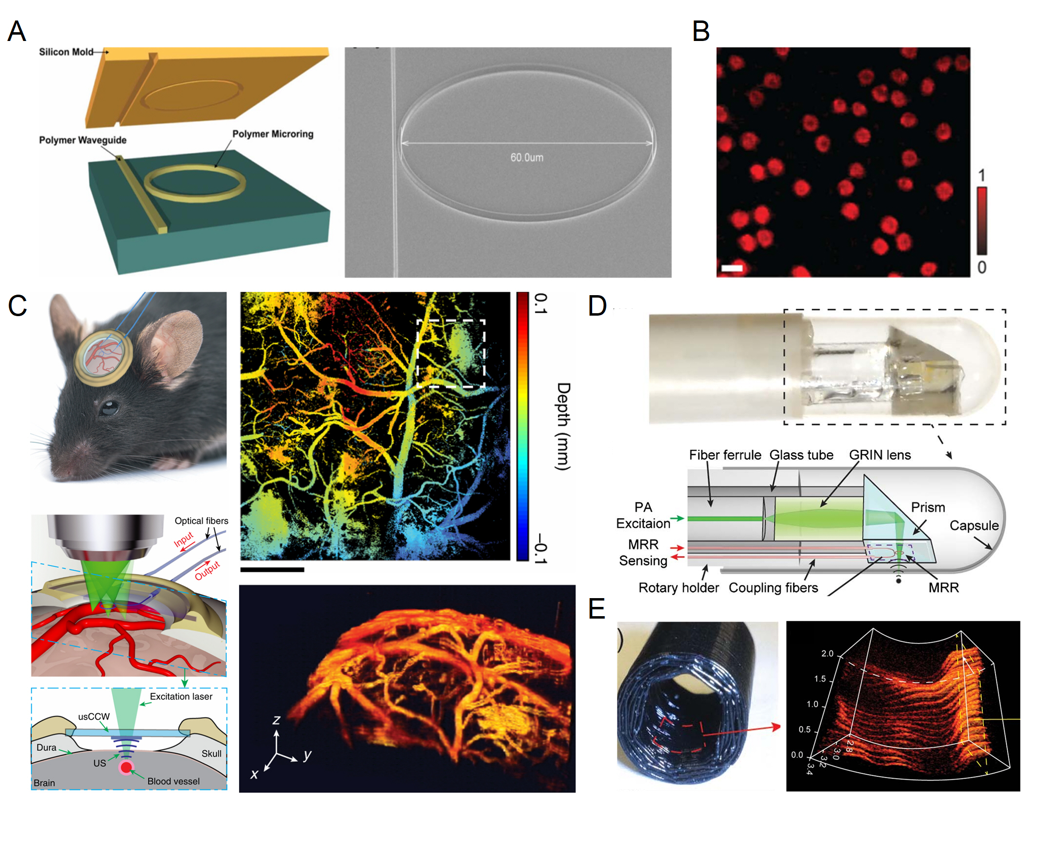
Microrings are the most used type of WGM microcavities for ultrasound sensing because they can be easily integrated on silicon chips, and have a wide choice of materials. Microrings are generally fixed directly to the substrate and it is difficult for an ultrasound to modulate the cavity length. Polymer materials with low Young’s modulus are good choices to increase the strain to improve the response to ultrasound. Some polymer materials such as polymethyl methacrylate (PMMA) [91, 92] and SU-8 [93], can be directly patterned using electron beam lithography (EBL). However, their optical factors are usually limited to the to range. Zhang et al. used a nanoimprinting method that used silicon as a mold (Figure 8A) to fabricate polystyrene (PS) microrings, and increased the factor of polymer microrings to by optimizing the nanoimprinting lithography [87]. Using this high- PS microring cavity, they have achieved a broadband response of 350 MHz, with a NEP of 105 Pa in this frequency range. Such a large response bandwidth allowed them to achieve sub-3 µm axial resolution in photoacoustic imaging [30]. They have also explored the potential of an ultrasound sensing array, with a one-dimensional array consisting of four microrings coupled with a single waveguide [94].

Polymer microrings have been used in photoacoustic imaging already in 2011, which offer a resolution of 5 µm laterally and 8 µm axially [97]. Using a polymer microring on a microscope coverslip, Li et al. conceived and fabricated an optically transparent ultrasound detector in 2014 [93]. It enabled high-sensitivity ultrasound detection over a wide receiving angle with a bandwidth of 140 MHz and an estimated NEP of 6.8 Pa. They verified an axial resolution of 5.3 µm by photoacoustic imaging of a carbon-black thin-film target. In 2015, they improved the system to achieve photoacoustic imaging of mouse erythrocytes as shown in Figure 8B, with an axial resolution of 2.1 µm [88]. In 2019 they reported a disposable ultrasound-sensing chronic cranial window featuring an integrated transparent nanophotonic ultrasound detector [89]. This detector was used to demonstrate photoacoustic microscopy of the cortical vascular network in live mice for 28 days as shown in Figure 8C. The small size of the microring also allows it to be used as a probe for endoscopy. Dong et al. have attached optically transparent polymer microrings and prisms together, allowing for a compact structure where excitation and detection are integrated [90], as shown in Figure 8D. They then achieved 3D photoacoustic imaging of the inner wall of a black plastic tube as well as the hair by rotating the probe, with the image shown in Figure 8E.
Silicon microrings have also been widely applied for ultrasound sensing, as the well-developed silicon photonics technology in the past few decades has allowed low-cost and mass fabrication of silicon microring cavities on silicon-on-insulator (SOI) platforms. In order to increase the mechanical compliance and thus the response of the silicon microring to ultrasound, optical micro-machined ultrasound sensors based on acoustic membranes have been developed, by etching away the silicon substrate underneath the silicon microring [95, 98], with the schematic and the optical microscope image of the structure shown in Figure 9A. Ultrasound pressure down to 0.4 Pa has been realized using this suspended silicon membrane [95]. The coupling region may also be deformed in this way resulting in a nonlinear readout. Then Yang et al. proposed to partially etch out the silicon substrate under the microring region to maintain a linear readout [99]. In 2021, Westerveld et al. fabricated a thin silicon film over a silicon microring with a 15 nm air gap between them, where ultrasound can change the air gap by causing the thin film to vibrate thus affecting the intracavity optical field of the microring [96]. An illustration of this structure, as well as its SEM and optical microscope images, are shown in Figure 9B. Using a microring with a diameter of 20 µm, NEP of 1.3 mPa Hz-1/2 has been realized in the 3-30 MHz frequency range, which is dominated by acoustomechanical noise. Figure 9C shows the results of their 3D photoacoustic imaging of a phantom consisting of three overlaying polyamide structures, obtained using this ultrasound sensor. They have also designed a one-dimensional array of ten microrings with their resonance wavelengths uniformly distributed over a free spectral range of 17 nm. The feasibility of the array detection was verified by measuring the delay in the response of different microrings to the ultrasound, as shown in the ultrasound signal time traces in Figure 9D. There are also microring-like structures such as microknots that can be used for ultrasound sensing [100, 101].
IV.3.2 Microspheres
The microsphere is another commonly used device geometry as it can be easily fabricated. For instance, silica microspheres can be fabricated by melting the end of a fiber tip using a CO2 laser or a fusion splicer. Microspheres are also often used for acoustic wave measurements [91, 102]. In 2014, Chistiakova et al. performed ultrasound sensing in water using an ultra-high silica microsphere [103]. They have simulated and experimentally verified that the microspheres can detect the echo signals of steel balls as well as water tanks as shown in Figure 10A. In 2020, Yang et al demonstrated an optomechanical microdevice based on Brillouin lasing in an optical microcavity as a sensitive unit to sense external light, sound, and microwave signals in the same platform [104], with the structure shown in Figure 10B. They have achieved a NEP of 267 µPa Hz-1/2, corresponding to a minimum detectable force of 10 pN Hz-1/2. The suspended microsphere structure utilized the mechanical vibration modes of the fiber to improve sensitivity. A thin fiber taper is usually used to couple light into the microcavity, and the coupling strength is very sensitive to the distance between the fiber taper and the microcavity. The displacement of the fiber taper caused by ultrasound is much greater than that of the microsphere, so measuring the change in the spacing between the fiber taper and the microsphere is an effective detection mechanism. This dissipative coupling mechanism was then investigated using microspheres by Meng et al. [22]. They found that the response to ultrasound through dissipative coupling was two orders of magnitude higher than the dispersive coupling mechanism. In order to make the microsphere ultrasound sensor more compact and robust to environmental disturbance, Sun et al. used glue to encapsulate the microspheres and fibers to avoid contamination [105], with the schematic illustration as well as the optical microscope images of the sensor before and after the encapsulation are shown in Figure 10C. A NEP of as low as 160 Pa at 20 MHz was achieved with the ultrasound response up to 70 MHz. As shown in Figure 10D, they have also used this sensor to successfully perform a 3D photoacoustic imaging of leaf veins. Ultrasound sensing in underwater environments has also been demonstrated using packaged microspheres [106].
IV.3.3 Microbubbles
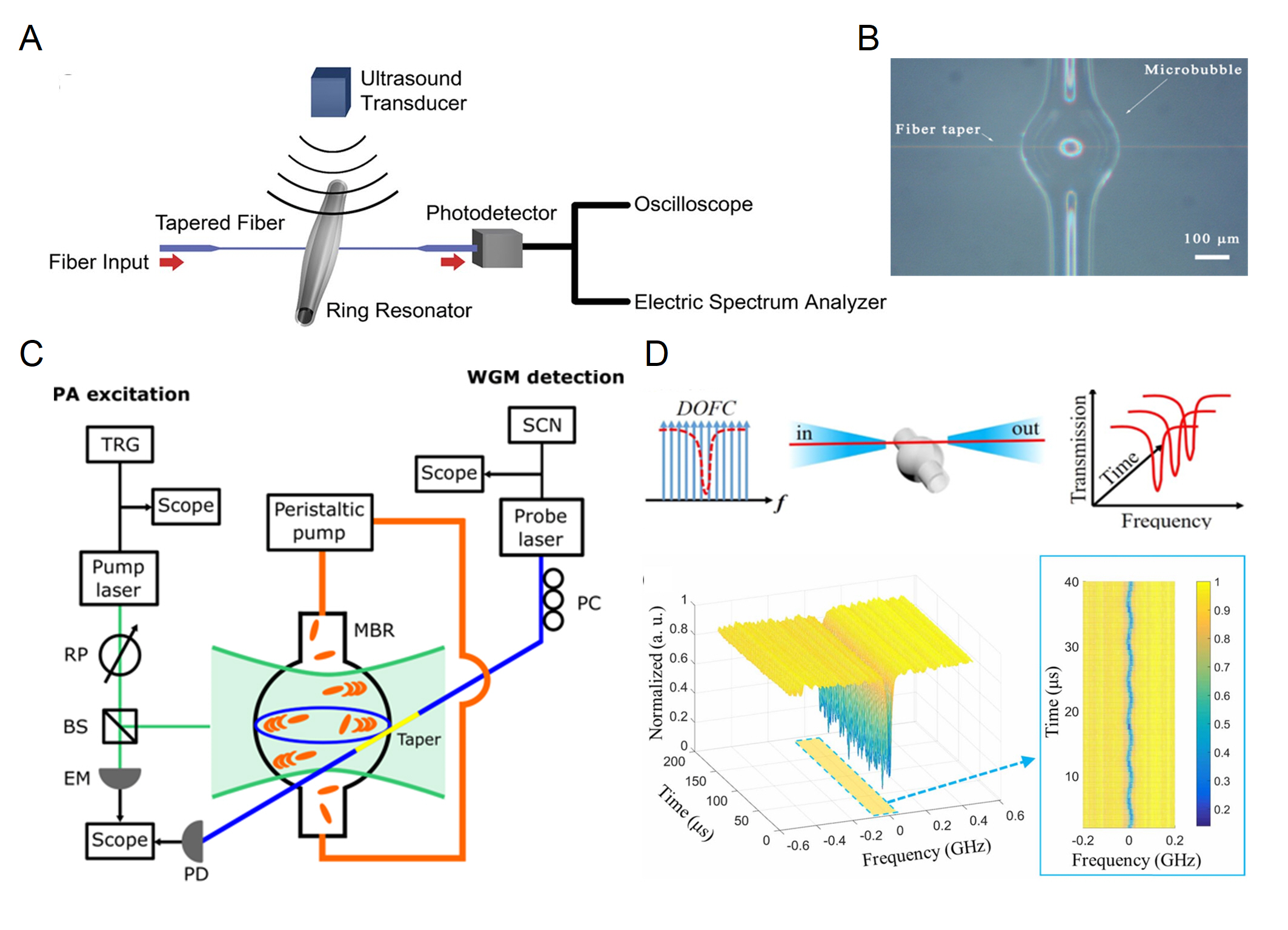
Both microrings and microspheres are solid microcavities that are less prone to deform than hollow structures. As a result, microbubble cavities fabricated using hollow capillaries have been extensively used for ultrasound sensing, and the walls of the capillaries can be made very thin, greatly enhancing the response to ultrasound. In 2017, Kim et al. developed a microbubble-based ultrasound sensor (Figure 11A) that has reached a NEP of 215 mPa Hz-1/2 and 41 mPa Hz-1/2 at 50 kHz and 800 kHz in air, respectively [107]. Microbubbles also use fiber tapers to couple light in and out, and need to be encapsulated in complex detection environments. Tu et al. used the encapsulated microbubble (Figure 11B) to detect acoustic waves at low frequencies in the 10 Hz to 100 kHz range and achieved a NEP of 2.2 mPa Hz-1/2 [108]. Benefiting from their encapsulated structure, microbubble sensors exhibited stable performance at different temperatures and static pressures. One advantage of microbubbles that distinguishes them from other microcavities is that their walls can serve as ultrasound transducers and the hollow structure inside acts as a sample container. In recent years, there have also been numerous works [111, 109, 112] that achieve photoacoustic detection of flowing samples by injecting nanoparticles into microbubbles, as shown in Figure 11C. This approach not only allows non-contact detection of the target particles but also allows the optical absorption spectra to be distinguished between different particles. In 2020, Pan et al. used a microbubble cavity combined with a digital optical frequency comb for ultrasound detection in air, which allows the full mode spectrum to be obtained at a timescale of the µs level. The working principle and experimental results of this work are shown in Figure 11D [110]. They have achieved a NEP of 4.4 mPa Hz-1/2 in the air at 165 kHz frequency. They also achieved a high positioning precision by measuring the phase difference between two microbubbles. The optical frequency comb was also used in microrings on the chip for ultrasound measurement [113].
IV.3.4 Microdisks and microtoroids


In addition to the above-mentioned three common types of WGM microcavities, microdisks have also been utilized for ultrasound sensing. There are several advantages of the microdisk structure. First, with the current microfabrication techniques, the sensing areas of microdisks can be easily made very large, which is helpful for improving the sensitivity. Second, the suspended microdisk structures increase their mechanical compliance thus enhancing their response to ultrasound, and decrease their mechanical damping rate thus allowing better thermal-noise-limited sensitivity (Eq. (4)). In 2019, Basiri-Esfahani et al. demonstrated an ultrasound sensor using a suspended spoked microdisk, and reached the noise region dominated by collisions of gas molecules [19]. SEM images of the suspended spoked microdisk are shown in Figure 12A. The spoke structure can make the microdisk more mechanically compliant, reducing mechanical losses and making it easier to reach the thermal-noise-limited regime. Figure 12B shows the noise power spectrum (black) of the microdisk around the mechanical mode as well as its ultrasound response at a single frequency (green curve). This allowed NEPs of 8-300 µPa Hz-1/2 at a range of frequencies between 1 kHz and 1 MHz. They used both dissipative and dispersive mechanisms to read out the different mechanical vibration modes. This study demonstrated a significant improvement in the sensitivity of ultrasound sensors in the range dominated by thermal noise. In 2022, Yang et al. performed a more systematic study on the thermal-noise-limited ultrasound sensitivity using suspended microdisks both theoretically and experimentally [114]. The sensitivity was optimized by varying the radius and thickness of the microdisk as well as using a trench structure around the disk. Top-view optical microscope image of a microdisk with a trench structure is shown in Figure 12C. Sensitivities of microdisks with different thicknesses and radii are shown in Figure 12D. A peak sensitivity of 1.18 µPa Hz-1/2 has been realized at 82.6 kHz, using a microdisk with a radius of 300 µm and a thickness of 2 µm.
The optical factors can be further improved by melting the edge of the microdisk to form a microtoroid with an atomically smooth surface and factors as high as 108 [61]. To further expand the frequency range of air-coupled ultrasound detection, Yang et al. then used microtoroids to improve the megahertz-frequency ultrasound detection [115], with the ultrasound measurement setup shown in Figure 13A. Using a microtoroid with a very thin silicon pedestal, they have achieved a mechanical factor of 700 at the first-order flapping mode at 2.56 MHz. Figure 13B shows the noise power spectra of the microtoroid ultrasound sensor with (green curve) and without (black curve) applying ultrasound at 2.56 MHz, with the displacement PSD () shown on the right axis. Figures 13C shows the ultrasound response at different frequencies, and Figure 13D shows the pressure and force sensitivities on the left and right axes respectively. Thermal-noise-limited sensitivity has been achieved in a frequency range of 0.6 MHz near the mechanical resonance. Sensitivities of 46 µPa Hz-1/2-10 mPa Hz-1/2 have been realized in the frequency range of 0.25-3.2 MHz.
IV.4 Performance comparison
| Structure | factor |
|
|
|
|
|||||||||
| FP | Diaphragm [49] | - | 0.01 | 0.022 | 0.060 | Around 80∘ | ||||||||
| F-P etalon [41] | - | 1 | 22.5 | 0.450 | <20∘ | |||||||||
|
>105 | 3.5 | >20 | 2.1 | 180° | |||||||||
|
- | 0.7 | 0.8 | 3.4 | 180∘ | |||||||||
|
103 | - | >15 | 0.03-0.1 | 120∘ | |||||||||
| -BG | FBG [15] | 2105 | 6.5 | 3 | (NEP) 440 Pa | - | ||||||||
| FBG [55] | 1.9105 | 25 | 36 | (NEP) 88 Pa | 153∘ | |||||||||
| WBG [56] | 105 | - | 230 | 9 | 148∘ | |||||||||
| WBG [57] | - | - | 200 | 2.2 | - | |||||||||
| WGM | Microring [30] | 105 | - | 350 (-3 dB) | (NEP) 105 Pa | - | ||||||||
| Microring [88] | 104 | - | 280 | (NEP) 6.8 Pa | 14∘ | |||||||||
| Microring [95] | 104 | 0.76 | 0.14 | (NEP) 0.4 Pa | - | |||||||||
| Microring [96] | 104 | - | 27 | 1.3 | 120° | |||||||||
| Microsphere [103] | 9.5107 | 40 | 5 | (NEP) 0.535 Pa | - | |||||||||
| Microsphere [104] | 108 | 0.0057 | - | 0.267 | - | |||||||||
| Microsphere [105] | 105 | 20 | 70 | (NEP) 100 Pa | - | |||||||||
| Microsphere [22] | 106 | 0.14 | - | 1.29 | - | |||||||||
| Microbubble [107] | 3.5107 | 0.8 | 0.2 | 41 | - | |||||||||
| Microbubble [110] | 3107 | 0.165 | - | 4.4 | - | |||||||||
| Microbubble [108] | 5.2105 | 0.001 | 0.1 | 2.2 | 105.5∘ | |||||||||
| Microdisk [19] | 3.6106 | 0.318 | - | 0.008-0.3 | - | |||||||||
| Microdisk [114] | 3106 | 0.0826 | - | 0.00118 | - | |||||||||
| Microtorid [115] | 107 | 2.56 | 1.13 | 0.046-10 | - |
-
•
CF: center frequency; BW: bandwidth
Table 1 summarizes the main parameters of the three types of optical microcavity-based ultrasound sensors, including optical factor, center frequency, bandwidth, NEPD or NEP, and acceptance angle. F-P cavities can achieve an optical factor of about 104 to 105 with a highly reflective dielectric layer. The optical factor is at the same level for -BGs, and their factors can be further increased by increasing the grating length. Among the three types of optical microcavites, WGM microcavities can achieve the highest optical factors, especially for microspheres, microbubbles, and microtoroids, which are at the level of -. Selecting materials with lower optical absorption losses, such as silicon nitride, can improve the optical factors of microrings [116]. Higher optical factors allow the thermal-noise-limited sensitivity to be achieved, leading to a lower NEP. Most of the sensors with NEP to the micropascal level have exploited the mechanical resonances of the structures to achieve the thermal-noise-limited sensitivity, except for a few millimeter-scale F-P cavities. However, mechanical resonances can lead to smaller detection bandwidth, which can affect certain applications. For most imaging applications, bandwidth at the megahertz level is required, but only some sensors can detect megahertz frequency ultrasound in water, due to the large propagation loss of high-frequency ultrasound waves. Air-coupled high-sensitivity ultrasound detection above 1 MHz frequency was only realized using a microtoroid cavity because of the even larger absoprtion loss in air. Transducers on optical fibers generally have wider acceptance angles and are better suited to receive ultrasound signals from multiple directions. The fiber itself is a good optical transmission device and is easy to connect to external devices, such as lasers. Sensors integrated onto a chip have slightly narrower acceptance angles but offer advantages of low cost, low power consumption, and mass production. On the other hand, stand-alone sensors face the challenge of stabilizing packaging for practical applications outside of the laboratory. For 2D and 3D imaging, the use of multiple sensor arrays working simultaneously can reduce the need for mechanical moving parts and shorten the imaging time. While 2D array multi-channel parallel sensing has already been achieved with F-P cavities on optical fibers, the development of array sensing is still in its infancy, as only one-dimensional arrays of -BGs and WGM microcavities have been demonstrated so far.
V Conclusion
Over the past few decades, optical ultrasound sensors have merged and demonstrated superior sensitivity and bandwidth compared to traditional piezoelectric sensors. Among them, recently developed optical microcavity ultrasound sensors offer the advantages of high sensitivity, broad bandwidth, and miniaturization, and have extensive applications in ultrasound imaging, photoacoustic sensing, etc. This review discusses ultrasound sensing work using optical microcavities. At the beginning, we introduce the sensing principles and the readout mechanisms and discuss the key parameters of microcavity ultrasound sensors. Previous work has shown that thermal noise is the fundamental limitation of NEP, and in this review, we have discussed the factors that influence the sensor response and sensitivity. We then present a comprehensive overview of the works on ultrasound sensing using three different types of optical microcavities, including F-P cavities, -phase-shifted Bragg gratings, and WGM microcavities. A performance comparison of different microcavity ultrasound sensors is also provided. While F-P cavity-based ultrasound sensors have low NEPs, they usually require suspended thin film structures and have a relatively large sensing area. In contrast, solid F-P cavities have inferior sensitivities but much larger response bandwidth. Fiber-based F-P cavities allow almost full spatial angle response and multi-channel parallel sensing. -BGs have the advantages of broadband response, large acceptance angle, multi-parameter sensing, and ease of on-chip integration, but require improved sensitivity. WGM microcavities can achieve higher sensitivities, due to the higher optical and mechanical factors which allow thermal-noise-limited sensitivities to be reached. However, WGM microcavities are more sensitive to the direction of ultrasonic waves, making it difficult to achieve a full-angle response. With the development of both science and technology, the performance of optical microcavity ultrasound sensors is expected to further improve, with lower NEPs, broader bandwidths, and larger acceptance angles. Their potential for parallel sensing needs to be further exploited, for high-speed imaging and sensing applications. This could be realized by combining multi-wavelength frequency comb sources [117] with an ultrasound sensor array. In the near future, We expect that optical microcavities will bring new opportunities for ultrasound sensing in applications such as photoacoustic imaging and non-destructive detection, etc.
Conflict of Interest
The authors declare that the research was conducted in the absence of any commercial or financial relationships that could be construed as a potential conflict of interest.
Author Contributions
XC conducted the literature research, prepared the figures and tables, and wrote the manuscript. HY assisted with the manuscript writing and figure preparation. BBL supervised the manuscript writing process, including the structure design and revision, and provided critical feedback. All authors participated in the manuscript revision, reviewed the final draft, and gave their approvals for submission.
Funding
This work is supported by The National Key Research and Development Program of China (2021YFA1400700), the National Natural Science Foundation of China (NSFC) (62222515, 12174438, 91950118, 11934019), and the basic frontier science research program of Chinese Academy of Sciences (ZDBS-LY- JSC003). This work is also supported by the Micro/nano Fabrication Laboratory of Synergetic Extreme Condition User Facility (SECUF).
References
- Hauptmann et al. [2002] P. Hauptmann, N. Hoppe, and A. Püttmer, Application of ultrasonic sensors in the process industry, Meas Sci Technol 13, R73 (2002).
- Ouyang et al. [2019] Y. Ouyang, Z. Zhou, W. Wu, J. Tian, F. Xu, S. Wu, and P.-H. Tsui, A review of ultrasound detection methods for breast microcalcification, Math Biosci Eng 16, 1761 (2019).
- Guo et al. [2018] R. Guo, G. Lu, B. Qin, and B. Fei, Ultrasound imaging technologies for breast cancer detection and management: A review, Ultrasound Med Biol 44, 37 (2018).
- Regtien and Dertien [2018] P. Regtien and E. Dertien, 9 - acoustic sensors, in Sensors for Mechatronics (Second Edition), edited by P. Regtien and E. Dertien (Elsevier, 2018) 2nd ed., pp. 267–303.
- Lee and Roh [2017] W. Lee and Y. Roh, Ultrasonic transducers for medical diagnostic imaging, Biomed Eng Lett 7, 91 (2017).
- Manwar et al. [2020] R. Manwar, K. Kratkiewicz, and K. Avanaki, Overview of ultrasound detection technologies for photoacoustic imaging, Micromachines 11, 692 (2020).
- Fu et al. [2022] B. Fu, Y. Cheng, C. Shang, J. Li, G. Wang, C. Zhang, J. Sun, J. Ma, X. Ji, and B. He, Optical ultrasound sensors for photoacoustic imaging: a narrative review, Quant Imaging Med Surg 12, 1608 (2022).
- Wissmeyer et al. [2018] G. Wissmeyer, M. A. Pleitez, A. Rosenthal, and V. Ntziachristos, Looking at sound: optoacoustics with all-optical ultrasound detection, Light Sci Appl 7, 53 (2018).
- Ma et al. [2022a] J. Ma, X. Ma, and L. Xu, Optical ultrasound sensing for biomedical imaging, Measurement 200, 111620 (2022a).
- Rousseau et al. [2012] G. Rousseau, B. Gauthier, A. Blouin, and J.-P. Monchalin, Non-contact biomedical photoacoustic and ultrasound imaging, J Biomed Opt 17, 061217 (2012).
- Wang et al. [2019] J. Wang, H. Peng, P. Zhou, J. Guo, B. Jia, and H. Wu, Sound source localization based on michelson fiber optic interferometer array, Opt Fiber Technol 51, 112 (2019).
- Lamela et al. [2009] H. Lamela, D. Gallego, and A. Oraevsky, Optoacoustic imaging using fiber-optic interferometric sensors, Opt Lett 34, 3695 (2009).
- Bauer-Marschallinger et al. [2017] J. Bauer-Marschallinger, K. Felbermayer, and T. Berer, All-optical photoacoustic projection imaging, Biomed Opt Express 8, 3938 (2017).
- Rosenthal et al. [2014] A. Rosenthal, M. Omar, H. Estrada, S. Kellnberger, D. Razansky, and V. Ntziachristos, Embedded ultrasound sensor in a silicon-on-insulator photonic platform, Appl. Phys. Lett. 104, 021116 (2014), https://doi.org/10.1063/1.4860983 .
- Rosenthal et al. [2011] A. Rosenthal, D. Razansky, and V. Ntziachristos, High-sensitivity compact ultrasonic detector based on a pi-phase-shifted fiber Bragg grating, Opt. Lett. 36, 1833 (2011).
- Vahala [2003] K. J. Vahala, Optical microcavities, Nature 424, 839 (2003).
- Metcalfe [2014] M. Metcalfe, Applications of cavity optomechanics, Appl. Phys. Rev. 1, 031105 (2014).
- Li et al. [2021a] B.-B. Li, L. Ou, Y. Lei, and Y.-C. Liu, Cavity optomechanical sensing, Nanophotonics 10, 2799 (2021a).
- Basiri-Esfahani et al. [2019] S. Basiri-Esfahani, A. Armin, S. Forstner, and W. P. Bowen, Precision ultrasound sensing on a chip, Nat. Commun. 10, 132 (2019).
- Vollmer et al. [2008] F. Vollmer, S. Arnold, and D. Keng, Single virus detection from the reactive shift of a whispering-gallery mode, Proc Natl Acad Sci USA 105, 20701 (2008), https://www.pnas.org/doi/pdf/10.1073/pnas.0808988106 .
- Riobó et al. [2019] L. Riobó, Y. Hazan, F. Veiras, M. Garea, P. Sorichetti, and A. Rosenthal, Noise reduction in resonator-based ultrasound sensors by using a CW laser and phase detection, Opt. Lett. 44, 2677 (2019).
- Meng et al. [2022a] J.-W. Meng, S.-J. Tang, J. Sun, K. Shen, C. Li, Q. Gong, and Y.-F. Xiao, Dissipative acousto-optic interactions in optical microcavities, Phys. Rev. Lett. 129, 10.1103/PhysRevLett.129.073901 (2022a).
- Aspelmeyer et al. [2014] M. Aspelmeyer, T. J. Kippenberg, and F. Marquardt, Cavity optomechanics, Rev Mod Phys 86, 1391 (2014).
- Bowen and Milburn [2015] W. P. Bowen and G. J. Milburn, Quantum optomechanics, 1st ed. (CRC press, Boca Raton, 2015).
- Chan et al. [2019] J. Chan, Z. Zheng, K. Bell, M. Le, P. Hajireza, and J. Yeow, Photoacoustic imaging with capacitive micromachined ultrasound transducers: Principles and developments, Sensors 19, 3617 (2019).
- Bass et al. [1995] H. E. Bass, L. C. Sutherland, A. J. Zuckerwar, D. T. Blackstock, and D. M. Hester, Atmospheric absorption of sound: Further developments, J Acoust Soc Am 97, 680 (1995).
- Xu and Wang [2003] M. Xu and L. V. Wang, Analytic explanation of spatial resolution related to bandwidth and detector aperture size in thermoacoustic or photoacoustic reconstruction, Phys Rev E 67, 056605 (2003).
- Yao and Wang [2013] J. Yao and L. V. Wang, Photoacoustic microscopy, Laser Photon. Rev. 7, 758 (2013), https://onlinelibrary.wiley.com/doi/pdf/10.1002/lpor.201200060 .
- Zheng et al. [2018] Z. Zheng, S. Na, A. I.-H. Chen, Z. Li, L. L. P. Wong, Z. Sun, Y. Yao, P. Liu, and J. T. W. Yeow, Development of a novel cmut-based concentric dual-element ultrasonic transducer: Design, fabrication, and characterization, J Microelectromech Syst 27, 538 (2018).
- Zhang et al. [2014a] C. Zhang, T. Ling, S.-L. Chen, and L. J. Guo, Ultrabroad bandwidth and highly sensitive optical ultrasonic detector for photoacoustic imaging, ACS Photonics 1, 1093 (2014a).
- Rebling et al. [2016] J. Rebling, O. Warshavski, C. Meynier, and D. Razansky, Optoacoustic characterization of broadband directivity patterns of capacitive micromachined ultrasonic transducers, J Biomed Opt 22, 041005 (2016).
- Guggenheim et al. [2017] J. A. Guggenheim, J. Li, T. J. Allen, R. J. Colchester, S. Noimark, O. Ogunlade, I. P. Parkin, I. Papakonstantinou, A. E. Desjardins, E. Z. Zhang, and P. C. Beard, Ultrasensitive plano-concave optical microresonators for ultrasound sensing, Nat. Photonics 11, 714 (2017).
- Dong et al. [2017] B. Dong, C. Sun, and H. F. Zhang, Optical detection of ultrasound in photoacoustic imaging, IEEE Trans Biomed Eng 64, 4 (2017).
- Zhang et al. [2014b] Z. Zhang, B. Dong, H. Li, F. Zhou, H. F. Zhang, and C. Sun, Theoretical and experimental studies of distance dependent response of micro-ring resonator-based ultrasonic detectors for photoacoustic microscopy, J Appl Phys 116, 144501 (2014b).
- Xu et al. [2014] F. Xu, J. Shi, K. Gong, H. Li, R. Hui, and B. Yu, Fiber-optic acoustic pressure sensor based on large-area nanolayer silver diaghragm, Opt. Lett. 39, 2838 (2014).
- Zhang et al. [2018] W. Zhang, F. Chen, W. Ma, Q. Rong, X. Qiao, and R. Wang, Ultrasonic imaging of seismic physical models using a fringe visibility enhanced fiber-optic Fabry-Perot interferometric sensor, Opt. Express 26, 11025 (2018).
- Ma et al. [2020] J. Ma, Y. He, X. Bai, L.-P. Sun, K. Chen, K. Oh, and B.-O. Guan, Flexible microbubble-based Fabry–Pérot cavity for sensitive ultrasound detection and wide-view photoacoustic imaging, Photon. Res. 8, 10.1364/prj.394941 (2020).
- Colchester et al. [2019] R. J. Colchester, C. Little, G. Dwyer, S. Noimark, E. J. Alles, E. Z. Zhang, C. D. Loder, I. P. Parkin, I. Papakonstantinou, P. C. Beard, M. C. Finlay, R. D. Rakhit, and A. E. Desjardins, All-optical rotational ultrasound imaging, Sci. Rep. 9, 5576 (2019).
- Ansari et al. [2018] R. Ansari, E. Z. Zhang, A. E. Desjardins, and P. C. Beard, All-optical forward-viewing photoacoustic probe for high-resolution 3D endoscopy, Light Sci. Appl. 7, 75 (2018).
- Ma et al. [2022b] X. Ma, M. Fan, Y. Cai, L. Xu, and J. Ma, A Fabry–Perot fiber-optic array for photoacoustic imaging, IEEE Trans. Instrum. Meas. 71, 1 (2022b).
- Preisser et al. [2016] S. Preisser, W. Rohringer, M. Liu, C. Kollmann, S. Zotter, B. Fischer, and W. Drexler, All-optical highly sensitive akinetic sensor for ultrasound detection and photoacoustic imaging, Biomed. Opt. Express 7, 4171 (2016).
- Hornig et al. [2022] G. J. Hornig, K. G. Scheuer, E. B. Dew, R. Zemp, and R. G. DeCorby, Ultrasound sensing at thermomechanical limits with optomechanical buckled-dome microcavities, Opt. Express 30, 33083 (2022).
- Arcizet et al. [2006] O. Arcizet, P.-F. Cohadon, T. Briant, M. Pinard, A. Heidmann, J.-M. Mackowski, C. Michel, L. Pinard, O. Français, and L. Rousseau, High-sensitivity optical monitoring of a micromechanical resonator with a quantum-limited optomechanical sensor, Phys. Rev. Lett. 97, 133601 (2006).
- Mason et al. [2019] D. Mason, J. Chen, M. Rossi, Y. Tsaturyan, and A. Schliesser, Continuous force and displacement measurement below the standard quantum limit, Nat Phys 15, 745 (2019).
- Schreppler et al. [2014] S. Schreppler, N. Spethmann, N. Brahms, T. Botter, M. Barrios, and D. M. Stamper-Kurn, Optically measuring force near the standard quantum limit, Science 344, 1486 (2014), https://www.science.org/doi/pdf/10.1126/science.1249850 .
- Guzmán Cervantes et al. [2014] F. Guzmán Cervantes, L. Kumanchik, J. Pratt, and J. M. Taylor, High sensitivity optomechanical reference accelerometer over 10 kHz, Appl. Phys. Lett. 104, 221111 (2014), https://doi.org/10.1063/1.4881936 .
- Jathoul et al. [2015] A. P. Jathoul, J. Laufer, O. Ogunlade, B. Treeby, B. Cox, E. Zhang, P. Johnson, A. R. Pizzey, B. Philip, T. Marafioti, M. F. Lythgoe, R. B. Pedley, M. A. Pule, and P. Beard, Deep photoacoustic imaging of mammalian tissues using a tyrosinase-based genetic reporter, Nat. Photonics 9, 239 (2015).
- Yin et al. [2019] X. Yin, Y. Shen, D. Su, and Z. Shao, High-spatial-resolution ultrasonic sensor using a fiber-optic Fabry–Perot interferometer, Opt. Commun. 453, 124422 (2019).
- Ma et al. [2013] J. Ma, H. Xuan, H. L. Ho, W. Jin, Y. Yang, and S. Fan, Fiber-optic Fabry–Pérot acoustic sensor with multilayer graphene diaphragm, IEEE Photonics Technol. Lett. 25, 932 (2013).
- Zhang et al. [2017] W. Zhang, R. Wang, Q. Rong, X. Qiao, T. Guo, Z. Shao, J. Li, and W. Ma, An optical fiber Fabry-Perot interferometric sensor based on functionalized diaphragm for ultrasound detection and imaging, IEEE Photonics J 9, 1 (2017).
- Fan et al. [2019] H. Fan, L. Zhang, S. Gao, L. Chen, and X. Bao, Ultrasound sensing based on an in-fiber dual-cavity Fabry-Perot interferometer, Opt. Lett. 44, 3606 (2019).
- Ma et al. [2019] X. Ma, Y. Cai, B. Fu, L. Xu, and J. Ma, Fiber optic-based laser interferometry array for three-dimensional ultrasound sensing, Opt. Lett. 44, 5852 (2019).
- Yang et al. [2022] L. Yang, C. Dai, A. Wang, G. Chen, D. Xu, Y. Li, Z. Yan, and Q. Sun, Multi-channel parallel ultrasound detection based on a photothermal tunable fiber optic sensor array, Opt. Lett. 47, 3700 (2022).
- Liu and Han [2012] T. Liu and M. Han, Analysis of -phase-shifted fiber Bragg gratings for ultrasonic detection, IEEE Sens. J 12, 2368 (2012).
- Shnaiderman et al. [2017] R. Shnaiderman, G. Wissmeyer, M. Seeger, D. Soliman, H. Estrada, D. Razansky, A. Rosenthal, and V. Ntziachristos, Fiber interferometer for hybrid optical and optoacoustic intravital microscopy, Optica 4, 1180 (2017).
- Shnaiderman et al. [2020] R. Shnaiderman, G. Wissmeyer, O. Ulgen, Q. Mustafa, A. Chmyrov, and V. Ntziachristos, A submicrometre silicon-on-insulator resonator for ultrasound detection, Nature 585, 372 (2020).
- Hazan et al. [2022] Y. Hazan, A. Levi, M. Nagli, and A. Rosenthal, Silicon-photonics acoustic detector for optoacoustic micro-tomography, Nat. Commun. 13, 1488 (2022).
- Fomitchov and Krishnaswamy [2003] P. A. Fomitchov and S. Krishnaswamy, Response of a fiber Bragg grating ultrasonic sensor, Opt. Eng. 42, 956 (2003).
- Minardo et al. [2005] A. Minardo, A. Cusano, R. Bernini, L. Zeni, and M. Giordano, Response of fiber Bragg gratings to longitudinal ultrasonic waves, IEEE Trans Ultrason Ferroelectr Freq Control 52, 304 (2005).
- Wissmeyer et al. [2016] G. Wissmeyer, D. Soliman, R. Shnaiderman, A. Rosenthal, and V. Ntziachristos, All-optical optoacoustic microscope based on wideband pulse interferometry, Opt. Lett. 41, 1953 (2016).
- Armani et al. [2003] D. K. Armani, T. J. Kippenberg, S. M. Spillane, and K. J. Vahala, Ultra-high-Q toroid microcavity on a chip, Nature 421, 925 (2003).
- Lee et al. [2012] H. Lee, T. Chen, J. Li, K. Y. Yang, S. Jeon, O. Painter, and K. J. Vahala, Chemically etched ultrahigh- wedge-resonator on a silicon chip, Nat. Photonics 6, 369 (2012).
- Savchenkov et al. [2007] A. A. Savchenkov, A. B. Matsko, V. S. Ilchenko, and L. Maleki, Optical resonators with ten million finesse, Opt. Express 15, 6768 (2007).
- Liu et al. [2022] J. Liu, F. Bo, L. Chang, C.-H. Dong, X. Ou, B. Regan, X. Shen, Q. Song, B. Yao, W. Zhang, C.-L. Zou, and Y.-F. Xiao, Emerging material platforms for integrated microcavity photonics, Sci. China Phys. Mech. Astron. 65, 104201 (2022).
- Jiang et al. [2020] X. Jiang, A. J. Qavi, S. H. Huang, and L. Yang, Whispering-gallery sensors, Matter 3, 371 (2020).
- Sansa et al. [2020] M. Sansa, M. Defoort, A. Brenac, M. Hermouet, L. Banniard, A. Fafin, M. Gely, C. Masselon, I. Favero, G. Jourdan, and S. Hentz, Optomechanical mass spectrometry, Nat. Commun. 11, 3781 (2020).
- Suh et al. [2016] M.-G. Suh, Q.-F. Yang, K. Y. Yang, X. Yi, and K. J. Vahala, Microresonator soliton dual-comb spectroscopy, Science 354, 600 (2016), https://www.science.org/doi/pdf/10.1126/science.aah6516 .
- Gavartin et al. [2012] E. Gavartin, P. Verlot, and T. J. Kippenberg, A hybrid on-chip optomechanical transducer for ultrasensitive force measurements, Nat. Nanotechnol. 7, 509 (2012).
- Li et al. [2020] B.-B. Li, G. Brawley, H. Greenall, S. Forstner, E. Sheridan, H. Rubinsztein-Dunlop, and W. P. Bowen, Ultrabroadband and sensitive cavity optomechanical magnetometry, Photon. Res. 8, 1064 (2020).
- Liao and Yang [2021] J. Liao and L. Yang, Optical whispering-gallery mode barcodes for high-precision and wide-range temperature measurements, Light Sci. Appl. 10, 32 (2021).
- Li et al. [2010] B.-B. Li, Q.-Y. Wang, Y.-F. Xiao, X.-F. Jiang, Y. Li, L. Xiao, and Q. Gong, On chip, high-sensitivity thermal sensor based on high-Q polydimethylsiloxane-coated microresonator, Appl. Phys. Lett. 96, 251109 (2010), https://doi.org/10.1063/1.3457444 .
- Yu et al. [2022] X.-C. Yu, S.-J. Tang, W. Liu, Y. Xu, Q. Gong, Y.-L. Chen, and Y.-F. Xiao, Single-molecule optofluidic microsensor with interface whispering gallery modes, Proc. Natl. Acad. Sci. U.S.A. 119, e2108678119 (2022), https://www.pnas.org/doi/pdf/10.1073/pnas.2108678119 .
- Jin et al. [2021] M. Jin, S.-J. Tang, J.-H. Chen, X.-C. Yu, H. Shu, Y. Tao, A. K. Chen, Q. Gong, X. Wang, and Y.-F. Xiao, 1/f-noise-free optical sensing with an integrated heterodyne interferometer, Nat. Commun. 12, 1973 (2021).
- Yang et al. [2021] D.-Q. Yang, J.-h. Chen, Q.-T. Cao, B. Duan, H.-J. Chen, X.-C. Yu, and Y.-F. Xiao, Operando monitoring transition dynamics of responsive polymer using optofluidic microcavities, Light Sci. Appl. 10, 128 (2021).
- Tang et al. [2021] S.-J. Tang, P. H. Dannenberg, A. C. Liapis, N. Martino, Y. Zhuo, Y.-F. Xiao, and S.-H. Yun, Laser particles with omnidirectional emission for cell tracking, Light Sci. Appl. 10, 23 (2021).
- Shen et al. [2016] B.-Q. Shen, X.-C. Yu, Y. Zhi, L. Wang, D. Kim, Q. Gong, and Y.-F. Xiao, Detection of single nanoparticles using the dissipative interaction in a high- microcavity, Phys. Rev. Appl. 5, 024011 (2016).
- Baaske et al. [2014] M. D. Baaske, M. R. Foreman, and F. Vollmer, Single-molecule nucleic acid interactions monitored on a label-free microcavity biosensor platform, Nat. Nanotechnol. 9, 933 (2014).
- Shao et al. [2013] L. Shao, X.-F. Jiang, X.-C. Yu, B.-B. Li, W. R. Clements, F. Vollmer, W. Wang, Y.-F. Xiao, and Q. Gong, Detection of single nanoparticles and lentiviruses using microcavity resonance broadening, Adv. Mater. 25, 5616 (2013), https://onlinelibrary.wiley.com/doi/pdf/10.1002/adma201302572 .
- Li et al. [2014a] B.-B. Li, W. R. Clements, X.-C. Yu, K. Shi, Q. Gong, and Y.-F. Xiao, Single nanoparticle detection using split-mode microcavity raman lasers, Proc. Natl. Acad. Sci. U.S.A. 111, 14657 (2014a), https://www.pnas.org/doi/pdf/10.1073/pnas.1408453111 .
- Şahin Kaya Özdemir et al. [2014] Şahin Kaya Özdemir, J. Zhu, X. Yang, B. Peng, H. Yilmaz, L. He, F. Monifi, S. H. Huang, G. L. Long, and L. Yang, Highly sensitive detection of nanoparticles with a self-referenced and self-heterodyned whispering-gallery raman microlaser, Proc. Natl. Acad. Sci. U.S.A. 111, E3836 (2014), https://www.pnas.org/doi/pdf/10.1073/pnas.1408283111 .
- He et al. [2011] L. He, Ş. K. Özdemir, J. Zhu, W. Kim, and L. Yang, Detecting single viruses and nanoparticles using whispering gallery microlasers, Nat. Nanotechnol. 6, 428 (2011).
- Zhu et al. [2010] J. Zhu, S. K. Ozdemir, Y.-F. Xiao, L. Li, L. He, D.-R. Chen, and L. Yang, On-chip single nanoparticle detection and sizing by mode splitting in an ultrahigh-Q microresonator, Nat. Photonics 4, 46 (2010).
- Vollmer and Yang [2012] F. Vollmer and L. Yang, Review label-free detection with high-Q microcavities: a review of biosensing mechanisms for integrated devices, Nanophotonics 1, 267 (2012).
- Zhi et al. [2017] Y. Zhi, X.-C. Yu, Q. Gong, L. Yang, and Y.-F. Xiao, Single nanoparticle detection using optical microcavities, Adv. Mater. 29, 1604920 (2017), https://onlinelibrary.wiley.com/doi/pdf/10.1002/adma.201604920 .
- Liu et al. [2021a] W. Liu, Y.-L. Chen, S.-J. Tang, F. Vollmer, and Y.-F. Xiao, Nonlinear sensing with whispering-gallery mode microcavities: From label-free detection to spectral fingerprinting, Nano Letters 21, 1566 (2021a), pMID: 33356315, https://doi.org/10.1021/acs.nanolett.0c04090 .
- Yu et al. [2021] D. Yu, M. Humar, K. Meserve, R. C. Bailey, S. N. Chormaic, and F. Vollmer, Whispering-gallery-mode sensors for biological and physical sensing, Nat. Rev. Methods Primers 1, 83 (2021).
- Zhang et al. [2015] C. Zhang, S.-L. Chen, T. Ling, and L. J. Guo, Review of imprinted polymer microrings as ultrasound detectors: Design, fabrication, and characterization, IEEE Sens J 15, 3241 (2015).
- Dong et al. [2015] B. Dong, H. Li, Z. Zhang, K. Zhang, S. Chen, C. Sun, and H. F. Zhang, Isometric multimodal photoacoustic microscopy based on optically transparent micro-ring ultrasonic detection, Optica 2, 169 (2015).
- Li et al. [2019] H. Li, B. Dong, X. Zhang, X. Shu, X. Chen, R. Hai, D. A. Czaplewski, H. F. Zhang, and C. Sun, Disposable ultrasound-sensing chronic cranial window by soft nanoimprinting lithography, Nat. Commun. 10, 4277 (2019).
- Dong et al. [2014] B. Dong, S. Chen, Z. Zhang, C. Sun, and H. F. Zhang, Photoacoustic probe using a microring resonator ultrasonic sensor for endoscopic applications, Opt. Lett. 39, 4372 (2014).
- Li et al. [2021b] M. Li, Y. Wang, M. Tian, J. Cheng, X. Jiang, and Y. Tan, A compact and highly sensitive voice-eavesdropping microresonator, J Light Technol. 39, 6327 (2021b).
- Sun et al. [2008] H. Sun, A. Chen, B. C. Olbricht, J. A. Davies, P. A. Sullivan, Y. Liao, and L. R. Dalton, Direct electron beam writing of electro-optic polymer microring resonators, Opt. Express 16, 6592 (2008).
- Li et al. [2014b] H. Li, B. Dong, Z. Zhang, H. F. Zhang, and C. Sun, A transparent broadband ultrasonic detector based on an optical micro-ring resonator for photoacoustic microscopy, Sci. Rep. 4, 4496 (2014b).
- Maxwell et al. [2008] A. Maxwell, S. W. Huang, T. Ling, J. S. Kim, S. Ashkenazi, and L. J. Guo, Polymer microring resonators for high-frequency ultrasound detection and imaging, IEEE J Sel. Top. Quantum. Electron. 14, 191 (2008).
- Leinders et al. [2015] S. M. Leinders, W. J. Westerveld, J. Pozo, P. L. van Neer, B. Snyder, P. O’Brien, H. P. Urbach, N. de Jong, and M. D. Verweij, A sensitive optical micro-machined ultrasound sensor (OMUS) based on a silicon photonic ring resonator on an acoustical membrane, Sci. Rep. 5, 14328 (2015).
- Westerveld et al. [2021] W. J. Westerveld, M. Mahmud-Ul-Hasan, R. Shnaiderman, V. Ntziachristos, X. Rottenberg, S. Severi, and V. Rochus, Sensitive, small, broadband and scalable optomechanical ultrasound sensor in silicon photonics, Nat. Photonics 15, 341 (2021).
- Xie et al. [2011] Z. Xie, S. L. Chen, T. Ling, L. J. Guo, P. L. Carson, and X. Wang, Pure optical photoacoustic microscopy, Opt. Express 19, 9027 (2011).
- Peternella et al. [2017] F. G. Peternella, B. Ouyang, R. Horsten, M. Haverdings, P. Kat, and J. Caro, Interrogation of a ring-resonator ultrasound sensor using a fiber Mach-Zehnder interferometer, Opt. Express 25, 31622 (2017).
- Yang et al. [2020a] W. Yang, S. Song, K. Powell, X. Tian, L. Li, L. Nguyen, and X. Yi, Etched silicon-on-insulator microring resonator for ultrasound measurement, IEEE Photonics J 12, 1 (2020a).
- De Freitas et al. [2015] J. M. De Freitas, T. A. Birks, and M. Rollings, Optical micro-knot resonator hydrophone, Opt. Express 23, 5850 (2015).
- Chen et al. [2019] H. Chen, Z. Shao, Y. Hao, and Q. Rong, A high-frequency hydrophone using an optical fiber microknot resonator, Opt. Commun. 446, 77 (2019).
- Meng et al. [2022b] J.-W. Meng, P.-J. Zhang, S.-J. Tang, and Y.-F. Xiao, Ultrasound detection using a thermal-assisted microcavity raman laser, AAPPS Bulletin 32, 38 (2022b).
- Chistiakova and Armani [2014] M. V. Chistiakova and A. M. Armani, Photoelastic ultrasound detection using ultra-high- silica optical resonators, Opt. Express 22, 28169 (2014).
- Yang et al. [2020b] J. Yang, T. Qin, F. Zhang, X. Chen, X. Jiang, and W. Wan, Multiphysical sensing of light, sound and microwave in a microcavity Brillouin laser, Nanophotonics 9, 2915 (2020b).
- Sun et al. [2021] J. Sun, J.-W. Meng, S.-J. Tang, and C. Li, An encapsulated optical microsphere sensor for ultrasound detection and photoacoustic imaging, Sci. China Phys. Mech. Astron. 65, 224211 (2021).
- Wang et al. [2022] K. Wang, W. Heng, X.-Y. Wu, Z. Yong, D. Yang, R. Jiao, and C. Wang, Ultrasound sensing using packaged microsphere cavity in the underwater environment, Sensors 22, 4190 (2022).
- Kim et al. [2017] K. H. Kim, W. Luo, C. Zhang, C. Tian, L. J. Guo, X. Wang, and X. Fan, Air-coupled ultrasound detection using capillary-based optical ring resonators, Sci. Rep. 7, 109 (2017).
- Tu et al. [2022] X. Tu, Y. Wang, Z. Guo, Z. Chen, T. Huang, X. Wu, and W. Luo, Underwater acoustic wave detection based on packaged optical microbubble resonator, J Light Technol. 40, 6272 (2022).
- Frigenti et al. [2020] G. Frigenti, L. Cavigli, A. Fernández-Bienes, F. Ratto, S. Centi, T. García, G. Nunzi Conti, and S. Soria, Microbubble resonators for all-optical photoacoustics of flowing contrast agents, Sensors 20, 1696 (2020).
- Pan et al. [2020] J. Pan, B. Zhang, Z. Liu, J. Zhao, Y. Feng, L. Wan, and Z. Li, Microbubble resonators combined with a digital optical frequency comb for high-precision air-coupled ultrasound detectors, Photon. Res. 8, 303 (2020).
- Frigenti et al. [2019] G. Frigenti, L. Cavigli, A. Fernández-Bienes, F. Ratto, S. Centi, T. García-Fernández, G. Nunzi Conti, and S. Soria, Resonant microbubble as a microfluidic stage for all-optical photoacoustic sensing, Phys. Rev. Appl. 12, 014062 (2019).
- Frigenti et al. [2021] G. Frigenti, L. Cavigli, F. Ratto, S. Centi, T. V. Murzina, D. Farnesi, S. Pelli, S. Soria, and G. Nunzi Conti, Microbubble resonators for scattering-free absorption spectroscopy of nanoparticles, Opt. Express 29, 31130 (2021).
- Song et al. [2020] J. Song, J. Pan, L. Wan, Z. Chen, Y. Zhu, Z. Yang, Y. Chen, M. Zhang, X. Yi, and Z. Li, Ultrasound measurement using on-chip optical micro-resonators and digital optical frequency comb, J Light Technol. 38, 5293 (2020).
- Yang et al. [2022] H. Yang, X. Cao, Z.-G. Hu, Y. Gao, Y. Lei, M. Wang, Z. Zuo, X. Xu, and B.-B. Li, Micropascal-sensitivity ultrasound sensors based on optical microcavities, arXiv e-prints , arXiv:2211.07965 (2022), arXiv:2211.07965 [physics.optics] .
- Yang et al. [2022] H. Yang, Z.-G. Hu, Y. Lei, X. Cao, M. Wang, J. Sun, Z. Zuo, C. Li, X. Xu, and B.-B. Li, High-sensitivity air-coupled megahertz-frequency ultrasound detection using on-chip microcavities, Phys. Rev. Appl. 18, 034035 (2022).
- Liu et al. [2021b] J. Liu, G. Huang, R. N. Wang, J. He, A. S. Raja, T. Liu, N. J. Engelsen, and T. J. Kippenberg, High-yield, wafer-scale fabrication of ultralow-loss, dispersion-engineered silicon nitride photonic circuits, Nat. Commun. 12, 2236 (2021b).
- Sun et al. [2023] Y. Sun, J. Wu, M. Tan, X. Xu, Y. Li, R. Morandotti, A. Mitchell, and D. J. Moss, Applications of optical microcombs, Adv. Opt. Photon. 15, 86 (2023).