Smartphones with UWB: Evaluating the Accuracy and Reliability of UWB Ranging
Abstract
More and more consumer devices implement the IEEE Ultra-Wide Band (UWB) standard to perform distance measurements for sensitive tasks such as keyless entry and startup of modern cars, to find lost items using coin-sized trackers, and for smart payments. While UWB promises the ability to perform time-of-flight centimeter-accurate distance measurements between two devices, the accuracy and reliability of the implementation in up-to-date consumer devices have not been evaluated so far. In this paper, we present the first evaluation of UWB smartphones from Apple, Google, and Samsung, focusing on accuracy and reliability in passive keyless entry and smart home automation scenarios. To perform the measurements for our analysis, we build a custom-designed testbed based on a Gimbal-based platform for Wireless Evaluation (GWEn), which allows us to create reproducible measurements. All our results, including all measurement data and a manual to reconstruct a GWEn are published online. We find that the evaluated devices can measure the distance with an error of less than , but fail in producing reliable measurements in all scenarios. Finally, we give recommendations on how to handle measurement results when implementing a passive keyless entry system.
I Introduction
Wireless communication is the upcoming norm of interaction between users’ phones and other devices such as cars and IoT devices. Without the need to interact with their phone or any other key, a user will be able to unlock their car when approaching and start it up once inside. At home, smart devices react to our presence. Smart locks open doors when an authorized person is nearby, and smart thermostats regulate temperature based on the presence of owners and their phones. These are only a few examples of the use cases for wireless communication based on UWB, the newest wireless physical layer in smartphones, which allows two devices to perform Time-of-Flight (ToF)-based distance measurements. The first car that supports this feature using UWB on iPhones was released in 2022 [1]. However, while a smart light that does not turn on is merely an annoyance, many of the applications like unlocking doors and cars need to be both reliant and accurate to avoid theft or blocked access for the owners.
Different applications have varying needs when it comes to the properties of distance measurements. In general, we can divide them into active and passive use cases. In an active use case, a person wants to actively measure the distance to a certain point, e.g., to find a lost item. Since users are already interacting with their phones in this scenario, they can try to enhance the distance measurements deliberately by holding the smartphone differently or moving around to get a good signal. This is not the case in passive use cases like Passive Keyless Entry (PKE) and smart home automation systems, which are the focus of our work. In these systems, the smartphones start interactions automatically and the user should not be required to optimize the measurements, as this would defy the idea of a passive system. Instead, the systems need to rely only on the existing measurements and it is currently unclear how measurements behave when a UWB smartphone is positioned sub-optimal.
There are two principal use cases of passive distance measurements, which we consider in this work:
-
1.
A passive keyless entry system implemented in a car or a smart lock requires accurate distance measurements with an error of less than . If the error is larger, the locks may open unpredictably. This may result in an unauthorized person gaining access. Additionally, when the user is closer than , the measurements need to be performed reliably and fail at less than of cases to ensure a good user experience.
-
2.
A smart thermostat, speaker, or light can offer the ability to change its state depending on the presence of a person in the room. These systems can rely on measurements with accuracy in the order of meters. However, they require reliable measurements at distances of , because stopping the music or turning off the heating while the person is still present can be disruptive to the user experience. To achieve high reliability, good software support for apps on a smartphone is essential. Smart home apps need to be able to connect to devices and start UWB ranging seamlessly and reliably without disturbing the user and without failing.
Manufacturers of UWB chipsets advertise their devices as producing errors of less than [2, 3]. However, at of the time of writing, no publicly accessible evaluation of smartphones with UWB capabilities exists. We do not know how accurate and reliable UWB in a smartphone is. This raises a couple of issues that need to be addressed:
-
•
Reliability and Accuracy of UWB technology. People using UWB as a PKE system need to know if they can rely on accurate measurements. Without this, people will be less likely to adopt the technology and more likely to resist its implementation. A positive evaluation will provide peace of mind to people using a UWB-smartphone as a car key.
-
•
Implementation of UWB measurements. Manufacturers of IoT devices need to understand how accurately and reliably measurements are reported by smartphones to implement dependable algorithms.
-
•
Security. By design, UWB is secure against relay and signal amplification attacks. However, if paired with highly inaccurate and strongly fluctuating measurements the security gain is minimal. It, therefore, needs to be evaluated how current implementations are behaving. Many PKE systems of cars without UWB have been successfully attacked [4, 5] and it is questioned if UWB ToF measurements can solve the existing problems.
Our measurements and their evaluation address these concerns by providing data and a reproducible testbed to analyze future devices. The goal of this paper is to evaluate UWB in smartphones and to analyze if the measurements meet the requirements defined above of PKE systems and IoT smart home devices. To achieve this, we design and implement a GWEn testbed that allows the rotation of a device under test (DUT) by 360º in two axes. A manual on how to build our GWEn testbed is available online and the required software is open-source [6]. Researchers can assemble it to reproduce our measurements or evaluate new devices.
Utilizing our testbed, we perform reproducible UWB measurements with one smartphone each from Apple, Google, and Samsung and a DW3000 development kit from Qorvo. All measurements are performed in three different environments: Outside to measure a ground truth, in our lab that resembles an office environment used to evaluate smart home automation, and in a parking garage to evaluate PKE in cars. Each environment represents a real-world scenario in which UWB can be used for distance measurements. We present our results and cover the differences between each environment. All our measurement data is available online [7]. In addition, we discuss if UWB in smartphones can perform well enough to achieve the defined goals in accuracy and reliability, we compare our results against previous work which focused on UWB development kits, and we give recommendations for implementing a secure PKE system.
Our evaluation reveals the following:
- 1.
-
2.
Measurements are accurate enough for PKE systems. On average the devices measure an error of less than . This is independent of the smartphone’s orientation.
-
3.
UWB measurements produce outliers of several meters, which influences the accuracy of the measurements. However, the overall standard deviation of our measurements is generally less than .
- 4.
Our key contributions are:
-
1.
We are the first to perform measurements with UWB capable Apple, Samsung, and Google smartphones.
- 2.
-
3.
We present and evaluate our measurements on accuracy and reliability to show strengths and weaknesses of UWB ranging.
-
4.
We give recommendations to manufacturers to implement secure entry systems.
-
5.
All our measurement data, that we evaluate in this paper is available online.
-
6.
A manual on how to build a GWEn testbed and the required software are open-source.
II Background & Related Work
This section gives an introduction to UWB, the available hardware, applications, and how 3D printing can be used to allow reproducible measurements. According to the IEEE standards, UWB defines two modes: High-Rate Pulse Repetition Frequency (HRP) and Low-Rate Pulse Repetition Frequency (LRP). In our work, we focus on UWB HRP as it is the only mode supported by smartphones and used for Passive Keyless Entry and Start (PKES) systems in cars.
II-A UWB HRP Mode
Most systems that are currently deployed use the UWB HRP mode that has been first defined in 802.15.4a–2007[8]. Over the years, this mode has been integrated into the main standard, and it has been extended at last by 802.15.4–2020 and 802.15.4z. While 802.15.4–2020 added new data rates and pulse repetition frequencys, 802.15.4z added additional security mechanisms that should protect ranging measurements against external attacks (see Section II-A3). We explain the distinctive features of UWB, how to use it for ranging and locating devices, and its security properties.
II-A1 Physical Layer
The discussed UWB systems are pulse-based communication systems. On the physical layer, these systems send out short electromagnetic pulses instead of longer sine waves. These pulses have sharp edges to the maximum amplitude and a total duration of [9]. An example of such a pulse is visible in Figure 1.
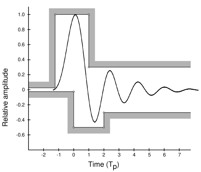
These sharp pulses allow accurate detection of the Time-of-Arrival (ToA) of the signal at the receiver. The U1 chipset in Apple’s devices has a clock that allows a theoretical resolution of 111Retrieved from reverse-engineering iOS.. Chipsets from Decawave offer up to [11, p.32].
UWB HRP supports 15 different channels with different bandwidths between and . Complex channels, formed by prepending a specific preamble to each frame, allow concurrent transmissions on the same channel [9].
The HRP mode defines three mean PRF at , and . All devices that we were testing used . Higher PRF achieve higher data rates and faster ranging. The UWB standard IEEE 802.15.4–2020 also defines an LRP mode which uses a lower PRF and a different security paradigm. We do not cover the details of this mode in this paper. There is currently no smartphone that supports LRP.
[0]iInitiator \node[below of=inst\theinstnum,node distance=0.8cm] (thread\thethreadnum) ; \newinst[3]rResponder \node[below of=inst\theinstnum,node distance=0.8cm] (thread\thethreadnum) ;
i)+0,-\theseqlevel*0.4-0.7*0.4) node (mess from) ; r)+0,-\theseqlevel*0.4-0.7*0.4) node (mess to) ; \draw[-¿,¿=angle 60] (mess from) – (mess to) node[midway, above] poll; ; \node[anchor=east] (t0) at (mess from) ; \node[anchor=west] (t1) at (mess to) ;
r)+0,-\theseqlevel*0.4-0.7*0.4) node (mess from) ; i)+0,-\theseqlevel*0.4-0.7*0.4) node (mess to) ; \draw[-¿,¿=angle 60] (mess from) – (mess to) node[midway, above] response, ; ; \node[anchor=west] (t2) at (mess from) ; \node[anchor=east] (t3) at (mess to) ;
i)+0,-\theseqlevel*0.4-0.7*0.4) node (mess from) ; r)+0,-\theseqlevel*0.4-0.7*0.4) node (mess to) ; \draw[-¿,¿=angle 60] (mess from) – (mess to) node[midway, above] ; ; \node[anchor=east] (t4) at (mess from) ; \node[anchor=west] (t5) at (mess to) ;
[] r)+0,-\theseqlevel*0.4-0.7*0.4) node (mess from) ; i)+0,-\theseqlevel*0.4-0.7*0.4) node (mess to) ; \draw[-¿,¿=angle 60] (mess from) – (mess to) node[midway, above] or ; ;
[decorate,decoration = brace] () – () node [align=center,midway,anchor=west] ;
[decorate,decoration = brace] () – () node [align=center,midway,anchor=east] ;
[decorate,decoration = brace] () – () node [align=center,midway,anchor=west] ;
[decorate,decoration = brace] () – () node [align=center,midway,anchor=east] ;
II-A2 Ranging mechanisms
To perform ranging, the UWB HRP transceivers use ToF based distance measurements. By measuring the time it took the signal to travel from the transmitter to the receiver, it is possible to calculate the distance between both devices. To remove the necessity of clock-synchronization between both devices, a Two-Way Ranging (TWR) mechanism is used. \Acds-twr is used to directly correct clock drifts and to ensure that both devices have a measurement result available. The Double-Sided Two-Way Ranging (DS-TWR) is depicted in Figure 2 and works as follows: The initiator starts by sending a poll message to the responder. The responder responds and also transmits the reply delay () to the initiator. The initiator now sends a second poll message and transmits its reply delay () and overall roundtrip time for the first message exchange () to the responder. The responder now calculates the final distance by using Equation 1. In a last (optional) message, the responder transmits the measured distance () or the second roundtrip time ().
| (1) |
II-A3 Security Properties
Earlier versions of UWB HRP in 802.15.4 did not have any security properties. The physical layer definitions were only supplemented by a simple MAC layer without any protection of ranging measurements against malicious interference.
This allowed severe attacks against UWB if used for ranging and localization. By listening to the UWB channel, an attacker can easily identify the used preamble, which starts every UWB frame. The early detection of the preamble allows an attacker to send frames with the same preamble earlier and thus reduce the measured distance [12]. Even sending static UWB pulses at a fixed interval to interfere with any surrounding ranging measurements caused distance reduction and enlargement attacks [13].
The current standard amendment IEEE 802.15.4z introduced a new protection mechanism against physical layer attacks [10]. Each UWB HRP frame now contains a Scrambled Timestamp Sequence (STS). The STS is a cryptographically secured sequence of pulses that is derived from a pseudo-random generator and a shared secret between the initiator and responder. Both devices in a ranging session will only accept frames that contain an expected STS and the location of the STS in the frame is used to derive accurate and secured timestamps.
An attacker that tries to reduce the measured distance by sending a packet with the same preamble on the same channel earlier does not succeed, because the STS changes with every frame and cannot be known in advance by an attacker. The receiver simply discards the frame. Previous research has shown that a distance reduction is still possible, but only at a low success rate (see Section II-D) [14].
II-B Available Hardware
We briefly introduce the available consumer hardware for UWB HRP devices in this section. There are currently three main manufacturers of chipsets in smartphones: Apple, NPX, and Qorvo. Table I gives an overview of available hardware.
The iPhone 11 in 2019 was the first mass-market smartphone that integrated a UWB HRP chip to perform ranging [15]. The previously released Bespoon phone has only been a public prototype, which is no longer on sale [16]. The Apple U1 UWB chip has been deployed to a number of devices: iPhone, Apple Watch, AirTag, and HomePod mini. The iPhone is the only device that has a multi-antenna UWB chip allowing angle of arrival (AoA) measurements.
Samsung was the second manufacturer which integrated UWB in their high-end Galaxy Note, Plus and Ultra lines [17]. They integrated the NXP SR100T chips into their Galaxy smartphones. The Samsung SmartTag+ integrates a precision finding feature leveraged by UWB and the NXP SR040 chip. While the SR100T chip also integrates AoA by using multiple antennas, the SR040 chip only uses one antenna and is designed for low-cost systems [2].
The Google Pixel 6 Pro was the first to introduce UWB to Google’s phones. This phone implements a UWB chipset from Qorvo. The chipset is based on the DWM3000 family of chips [18]. The Pixel 6 Pro also supports AoA measurements.
All chipsets are compliant with the open IEEE 802.15.4z standard and the proprietary Fine Ranging Consortium (FiRa) and Car Connectivity Consortium (CCC) standards. This allows theoretically wide interoperability between these chips. However, due to limited software support, Android and iOS smartphones are not able to interoperate, yet [19]. In this work, we focus on smartphones with UWB support: The Apple iPhone (11 and newer), Samsung Galaxy smartphones (S21 Ultra and newer), and Google Pixel (6 Pro and newer).
| Device | Chipset | No. Antennas | Supported Standards | Accuracy222As stated by chip manufacturer [20, 3] | Channel |
|---|---|---|---|---|---|
| Apple devices | Apple U1 | IEEE 802.15.4z, FiRa333FiRa Consortium [21], CCC444Car Connectivity Consortium [22], ANI555Apple Nearby Interaction [19] | - | 5, 9 | |
| Samsung Galaxy smartphones | NXP SR100T | 3 | IEEE 802.15.4z, FiRa\@footnotemark, CCC\@footnotemark | 5, 6, 8, 9 | |
| Google Pixel Pro | Qorvo DW3720 | 2 | IEEE 802.15.4z, FiRa\@footnotemark, CCC\@footnotemark | 5, 6 | |
| Qorvo DWM3000EVB | DW3110 | 1 | IEEE 802.15.4z, FiRa\@footnotemark, CCC\@footnotemark, ANI\@footnotemark | 5, 6 |
II-C Applications
Smartphones with UWB have a few applications in which the technology is used to provide an extra layer of security or positional awareness. We present major applications that are already deployed.
The Digital Key 3.0 allows hands-free keyless access using distance measurements of UWB in combination with Bluetooth Low Energy to check whether an authorized person is near the vehicle [23]. The vehicle unlocks automatically and can be started when the person sits inside (PKES). At the time of writing only iPhones support UWB car keys, while the Google Pixel offers support for near-field communication (NFC)-based car keys.
NXP and the ING bank announced that they will work on supporting UWB on Samsung smartphones to use it for payments to nearby users. \Acuwb is intended as an extra security layer and omits the need to exchange bank account numbers before sending a payment [24, 25].
uwb-tags are already widespread and allow the tracking of personal belongings. These tags are usually not much bigger than a coin, have an integrated power-saving UWB chip and can therefore run for several months on one charge. The precision finding feature uses UWB to measure the distance and the AoA to the missing tracker and shows that on the user’s smartphone [19, 26, 27].
Several smart home and Internet of Things (IoT) applications would benefit from the application of UWB. A smart door lock with UWB would increase the security over a Bluetooth Low Energy (BLE)-based version. In November 2022, Samsung announced plans for an aforesaid smart lock [28]. Presence detection of people in a room could be leveraged to control lighting and heating based on personal preferences. To the best of our knowledge, no smart home devices with UWB are available on the consumer market.
II-D Related Work
Many works focus on indoor-localization techniques based on UWB [29, 30, 31, 32]. Our work focuses on consumer smartphones, their UWB ranging accuracy, reliability, and the security implications that inaccurate measurements can have. Therefore, the related work can be separated into two areas, the general UWB accuracy and the security analyses of the UWB protocols. To the best of our knowledge, we are the first to evaluate and compare the UWB ranging accuracy of consumer smartphones.
II-D1 Ranging accuracy
Related work in this area mainly concentrates on the evaluation of available development kits for UWB hardware. Between 2015 and 2017, after the first UWB chipsets became available, the first evaluations on ranging accuracy and performance have been conducted [33, 34, 35]. During that time only the UWB HRP mode was available, and it was lacking any security measures. All devices evaluated during this time are no longer compatible with current UWB standards. In 2020, after the release of IEEE 802.15.4z with LRP and the STS to secure HRP measurements, studies have started to compare LRP and HRP in terms of energy consumption [36]. Works in 2022 also evaluate the accuracy of the DW3000 chipsets from Qorvo in development kits, like the DWM3000EVB [37, 30, 38]. The DW3000 has also been compared to LRP devices [30]. In 2022, researchers discovered that the default DW1000 antenna has an uneven radiation pattern and the researchers evaluated the ranging error from several angles by using unmanned aerial vehicles [29]. We compared several works with our result in Section VII-B.
II-D2 UWB Security
IEEE 802.15.4z HRP mode has been evaluated for its security and the first attacks on it have been discovered. Previous work analyses the theoretical potential for multipath effects that could cause a distance reduction attack [39]. Since no open-source implementations are available, a simulated HRP receiver according to the standard has been implemented and evaluated. Follow-up work has confirmed that the theoretical attack also works on devices that integrated Apple’s U1 UWB chip [14]. Practical distance reductions of several meters have been possible by using a DWM3000 UWB sending frames with low power and the same preamble at the same time as the other UWB transmitter. The success rate of the attack was less than . Hence, it shows that the applied security measures are not sufficient to stop all attacks.
gwen
III GWEn
The main goal of this work is to determine the ranging accuracy and reliability of UWB smartphones in a standardized, repeatable, reproducible, and automated way. This enables a systematic evaluation and comparison of our DUTs.
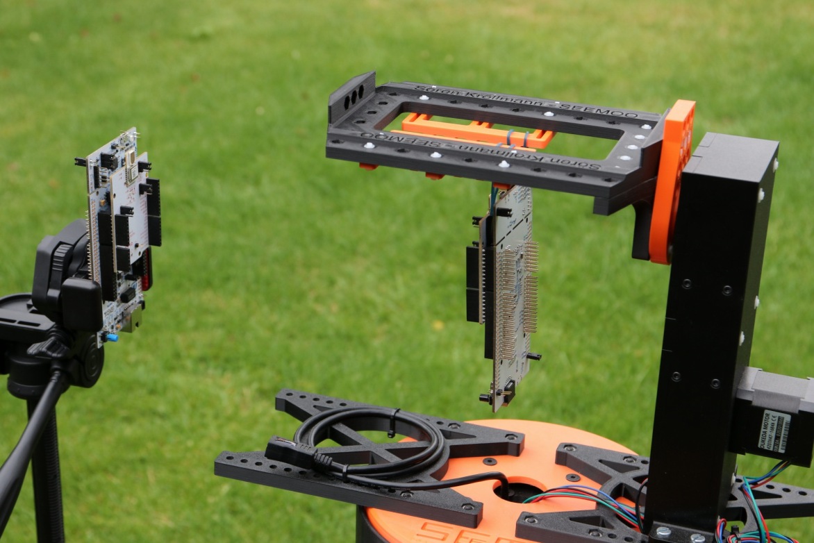
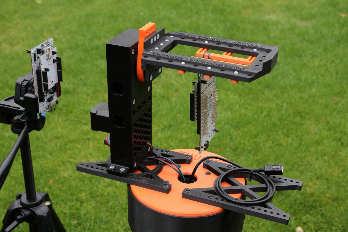
To accomplish this, we develop, build, and evaluate a GWEn. Figure 3 shows a labeled build of GWEn. It is equipped with two rotation axes, one in the base and one in the arm as depicted in Figure 3. Throughout this paper, the angle denotes the arm rotation around the x-axis and the angle denotes the base rotation around the y-axis.
III-A Measurements with GWEn
gwen is a multipurpose tool for conducting wireless measurements and evaluating antennas at a small scale.

Each axis can rotate the full 360° making it possible to position the DUT, attached to the holding plate, in any desired orientation with a resolution of 0.01°. A variety of devices can be attached to the holding plate, allowing all kinds of wireless transmission measurements or antenna evaluations. For an optimal measurement, the antenna of the DUT must be as close as possible to the intersection of the two rotation axes. The tower on the rotation plate can be moved further outward or inward to accommodate devices of different lengths. The holding plate on the tower can be moved further up or down to adapt GWEn to devices of different thicknesses. To be able to extract the measurement data from the DUT, it is connected to GWEn via a USB connection.
GWEn can be controlled over a web interface that is reachable via its own Wi-Fi hotspot. Furthermore, it’s also possible to create custom Python scripts that allow different movement patterns.
To create meaningful and repeatable measurements, we have developed a workflow for GWEn measurements:
-
1.
GWEn setup: This includes setting up GWEn at the test location, mounting the DUT and setting up the measurement parameters. Section V-A goes into more detail on the specific setup used in our work.
- 2.
-
3.
A measurement between two iPhones with the settings described in Section V-A takes 90 minutes. No monitoring of the system is required during this period.
-
4.
Download the measurement. After finishing the measurements, the recordings can be downloaded as zip files. Our evaluation software directly works on the generated zip files and generates graphs to evaluate the performance.
III-B Manufacturing
We designed GWEn to be D-printed using a fused deposition modeling D printer. Besides belts, screws, bearings and the electrical components all parts are D-printed. We use polylactic acid (PLA) as a printing material. \Acpla has only very little influence on electromagnetic signals [40]. of solid PLA adds about of measured distance to an UWB signal. We evaluate the interference introduced by GWEn with more detail in Section IV.
D-printing is a low-cost and widely available option that allows easy reproduction of desired parts. Furthermore, it enables modifications, as new parts can be designed and D-printed rapidly. It takes about days to print all parts on a Prusa i3 MK3S+ [41]. However, this time depends heavily on the printer and the print settings. Assembling GWEn and soldering up the electrical components requires additional 80 hours of manual work.
III-C Measurement recording
We programmed GWEn to interact with a variety of devices (see Table I) and process their UWB measurements. Since the devices come from different manufacturers and run with different software, GWEn offers the possibility to add new communication options with the help of sources. Each source is a plugin written in Python that has to be defined once and provides functions for GWEn to extract the necessary data from the device. For smartphones, we use device logs to extract ranging data from the device (see Section V-C). The source to be used for each measurement can be specified at the start of a measurement.
At the end of each measurement, GWEn creates a recording file. It contains a JSON file with the setup settings used to create the recording as well as all made distance measurements ordered by their respective base and arm angle. It is furthermore possible to add additional files, e.g., a complete log of the measurement. All measurement data is backed up constantly and can be restored.
IV Evaluation of GWEn
As described in Section III-B, a 1 cm thick PLA wall has a negligible effect on the signal. In addition to the parts printed from PLA, GWEn also contains motors, ball bearings and shafts. These parts consist of metal that interferes with the signal between the two devices. This is especially the case when the tower is directly between the two antennas. Therefore, before evaluating the data, it must be ensured that the measurement is not affected by GWEn’s test setup and procedure.
IV-A Maximum error
To evaluate the influence of GWEn on the recordings, we performed two tests using a pair of DW3000 UWB devices. First, we placed both devices facing each other with no obstructions between them in clear Line-of-Sight (LoS) (see Figure 4(a)). Second, we rotated the base of GWEn to such that the tower is now directly between both devices (see Figure 4(b)). We also turned the DW3000 again to ensure that they have the same orientation as in the first test. For both tests, we ensured that the distance between the DW3000 UWB devices is equal.
In each test, we performed UWB measurements. To assess the influence of GWEn, we calculated the mean measured distance and the standard deviation for both measurements. In LoS, without the tower, a mean value of with a standard deviation of was measured. With the tower, and were determined, respectively.
IV-B Reproducibility
We assess the reproducibility of measurements by using an experimental setup with two DW. One board was our DUT mounted to GWEn and the other board was mounted on a tripod. Both were placed apart. GWEn rotated a full at the base () and at the arm () at each base position. At each position, the DWs performed UWB distance measurements.
The same full measurement cycle was then performed three times in succession. Subsequent examination of the three records showed that the mean and standard deviation for all records were and , respectively. Figure 5 shows for each measurement the plot for a full rotation of the base with a fixed arm angle of . All graphs have very similar shapes, and we can see similar results when comparing different arm angles.
Finally, we tore down the measurement setup and set it up again one week later. We measured with the same parameters and compared the results. Figure 6 shows two plots one from the first recording described above and one from a fourth recording made one week later. Figure 6(a) and Figure 6(b) both show a rotation of the base () with the arm at . The general shape of the two measurements is similar, but we can see some deviations, which could have been caused by minor changes in the environment. The mean value is , less than the first measurements, but the standard deviation remained the same.
All tests combined show that GWEn only marginally influences UWB measurements and can therefore be used to evaluate UWB capable devices.
V Experimental setup
In this section, we detail how we set up our measurement device GWEn, how we configured each DUT, and how we were able to collect distance measurement data from UWB over a USB connection.
We evaluated each device listed in Table I in three different environments to see how multipath effects and reflections might change the results.
V-A Measurement Setup
Figure 7 shows the hardware setup for a typical measurement. The setup consists of GWEn, two devices to test, a laptop, and a tripod. The DUT is mounted on GWEn, which is placed on a camera tripod such that the DUT remains at a height of . This height should model the distance of a jeans’ pockets to the ground. The DUT has been placed such that its antennas were in the intersection of the rotation axis of GWEn (see Figure 8). The remote device is mounted on a tripod and a desired distance between them is set. The distance between both devices is measured using a laser meter or a measurement tape. The arm is set to by using an internal sensor that detects when the motor has rotated to the correct position. The base is aligned such that the tower is located at an angle of as shown in Figure 8, which we define as (see Figure 8).
The rotation axes of GWEn and according to labels are plotted in Figure 3 and detailed in Section III. For all our experiments GWEn performs these steps:
-
1.
Start at arm rotation and base rotation
-
2.
Rotate the arm by
-
3.
When the arm reaches , rotate the base by
-
4.
Rotate the arm by
-
5.
When the arm reaches , rotate the base by
-
6.
Continue with step 2 until the base reaches
At each position, we measure the distance and collect the measurements, before GWEn continues with the next step.
Each measurement for each pair of devices has been conducted in the same way in the same environments to ensure comparability. Once the measurement is started all operations for the measurement happen on GWEn and the external laptop is no longer needed. For UWB measurements, the ranging has to be started on the DUT and the remote device in advance.
Antenna locations
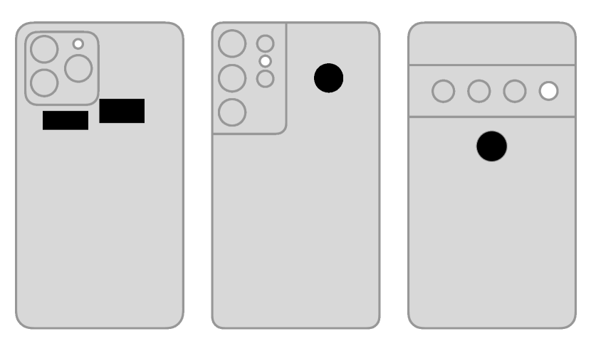
We identified the location of the UWB transmission antenna in smartphones by using an oscilloscope and manually searching for the location with the strongest signal. All manufacturers placed the antennas close to the rear cameras. Since they all offer multiple receive antennas to determine the AoA the receive antennas are often next to the transmission antenna [43]. We validated our claims by closely inspecting online device tear-downs [43, 44, 45, 46]. All UWB antennas are marked in Figures 9 and 10.
V-B Evaluation environments
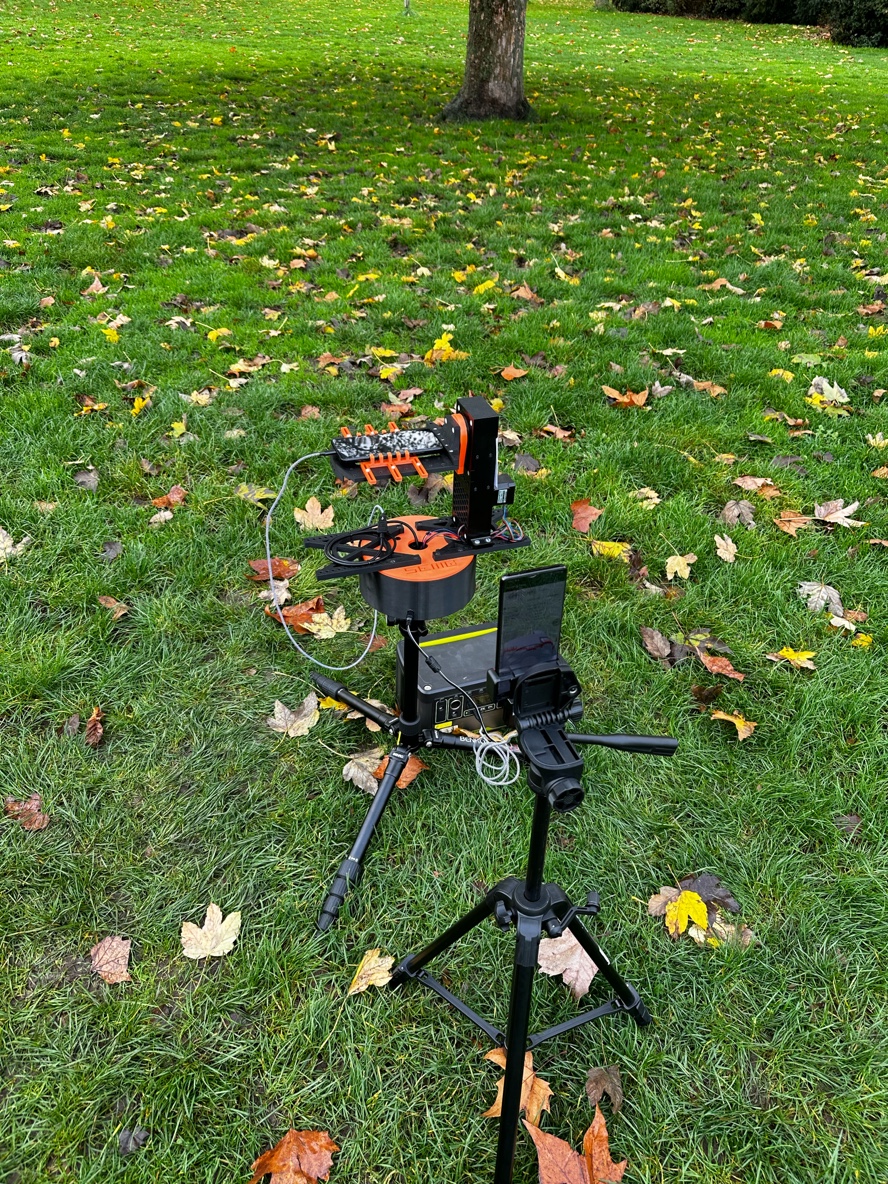
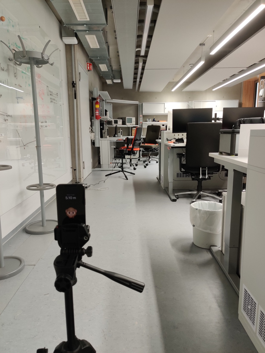
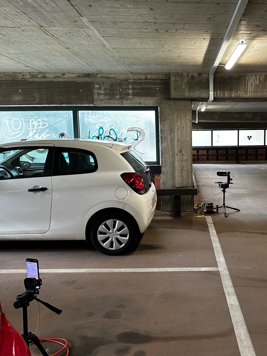
We decided on three environments: outside, our lab, and a parking garage. A photo of each environment is shown in Figure 11.
Outside
A location outside with no reflecting objects nearby is a good environment to measure a ground truth with a low amount of multipath interference. The soil-based ground cannot reflect signals well. There were no nearby Wi-Fi signals that could have interfered with our measurements. The only nearby Wi-Fi signal was emitted by GWEn itself and limited to the band, which does not interfere with our tested UWB channels. The setup is similar to the one used by [33, 34].
Lab
Our lab offers a range of difficulties for UWB measurements that can also occur in an office environment. Our measurement location was close to a glass whiteboard, several computers, monitors, and office furniture. These office environments are likely locations for future application of UWB–enabled locks that can replace the need for special key fobs.
Public parking garage
V-C Device configuration
All devices need to be configured in a way that they start measuring the distance using UWB. We, therefore, explain the different configuration options and how we initiated the measurements. As UWB is a rather new technology in consumer devices, there is no fully open application programming interface (API) available by any smartphone manufacturer, which would have allowed fine-grained configuration of the UWB chip. Therefore, the configuration of UWB parameters, like channel, preamble, data rate and STS may not be changed. In many cases, we were also not able to extract the used parameters after the measurement.
Apple
The Apple NearbyInteraction framework [47] can be used by any iOS app and can be configured to measure either the distance to another iPhone, Apple Watch or to a compatible UWB third-party chip. We use an iPhone 12 Pro as the DUT and an iPhone 12 mini as the remote device. Both devices utilize the same generation of Apple’s U1 chipset.
Samsung
Samsung and Google both implement the FiRa protocol and would be theoretically compatible with the other chipsets and the iPhone. Unfortunately, no documentation on how to initialize ranging with any other device is not available publicly.
The Samsung Galaxy S21 Ultra that we used for testing comes with an installed UWBTest app. This app is hidden and can only be launched by opening the telephone app and typing *#UWBTEST# in the phone number field. We use this app to run our UWB measurements between two Samsung devices because this has been the most reliable option on Android. We cannot determine which channel or preamble is used here. A Samsung Galaxy S21 Ultras is used as the DUT and the remote device.
So far, there are only the Google Pixel 6 Pro and Pixel 7 Pro available that integrate a UWB chip. The only supported feature with UWB is Android Nearby Share [48] and the Android 12 UWB API [49]. We developed a small test application that is able to perform UWB ranging between compatible Android devices. Unfortunately, this UWB API needs up to and may fail to measure the distance completely. All our measurements are conducted using Android 12. We configured the app to use channel 9 and the preamble code 11 for all our measurements. A Google Pixel 6 Pro is used as the DUT and the remote device. Additionally, we also performed all measurements with a Samsung Galaxy S21 Ultra as the remote device. Both measurements are compared in Section VI-F.
Qorvo
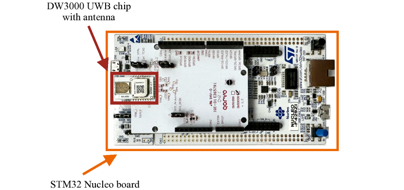
The Qorvo DWM3000EVB is a board that can be attached to an STM development board. By using the SDK provided by Qorvo, it’s possible to write programs that can execute simple ranging measurements. Their sample code already provides most features needed for our evaluation. We configured the devices to use a static STS and perform DS-TWR on channel 9 using preamble code 11.
V-D Measurement result extraction
Every device that we researched is able to generate results for the measurements and accessing them works differently on every device. As introduced in Section III, GWEn connects to all devices via USB to record measurement data while performing the measurement. We implemented separate parsers for each device that we support. If possible, we use raw measurements which are not enhanced by optimization algorithms.
Apple
Apple devices often use extensive logging but omit sensitive data from the logs. To allow developers to debug their apps, certain logs can be activated using a debug profile. We use the AirTag debug profile to enable rich logs from nearbyd, a process which handles all UWB related tasks [50]. With a USB connection to GWEn, we can fetch the logs and extract relevant measurement data. We extract raw measurements, as user-facing distance measurements are enhanced by custom machine learning algorithms.
Samsung
Samsung’s devices also offer the option to increase the log verbosity by activating verbose vendor logging in the developer settings. Then the smartphone logs all distance measurement data in a raw measurement and a calibrated measurement. Depending on the internal state the calibrated measurement may not be available. \Acgwen extracts both measurements using the adb logcat command line interface.
Google’s smartphones log the UWB distance measurements by default. Unfortunately, the logs are less verbose than Apple’s or Samsung’s. We, therefore, decide to use a custom logging format. We expect that all distance measurements on Google smartphones are raw measurements. Furthermore, we did not find any hints of a specially calibrated result or any machine learning-based enhancements.
Qorvo
We mounted the DWM3000EVB to an STM32 development board. By programming the STM32 board, we are able to create a serial connection between the board and GWEn. Two-way communication allows GWEn to instruct the board to perform new measurements and to receive measurement results from the board. All results are raw results without any calibration. We tested the effect of calibrating the chips briefly, but we could not identify larger differences if compared to not calibrated devices.
in\prntlen
VI Measurement Results
In total, we conducted measurement series at three environments using four different devices. All UWB capable smartphones have been evaluated at two different distances: and . We conducted the same measurements using the Qorvo DWM3000EVB as a reference. Measurements with larger distances were mostly not possible, since all smartphones fail to measure if the antennas are not directed at each other. All DUTs have been placed on GWEn as described in Section V. GWEn performed a base rotation () and a arm rotation () using a step size of . At each position, a minimum of distance measurements have been recorded. In this section, we state our measurement results, draw general statistics about each DUT, and take a look at each location to compare how devices behave differently depending on their environment.
VI-A Maximum distance
In an initial measurement, we evaluated the maximum measurable distance of all smartphones in our test set. We used an outside location that has no obstructions. The results are listed in Table II. The iPhone is able to continuously measure the longest distance. We identified that the maximum is artificially limited to about on the iPhone and on the Samsung Galaxy S21 Ultra. In our evaluation, the measurements stopped at exactly that distance. The Google Pixel performed the worst here, and it was not possible to get reliable measurements at larger distances. The distance does not seem to be limited artificially.
| Smartphone | Distance (m) |
|---|---|
| Apple iPhone 12 Pro | 40.0 |
| Samsung Galaxy S21 Ultra | 23.0 |
| Google Pixel 6 Pro | 11.6 |
VI-B Overall results
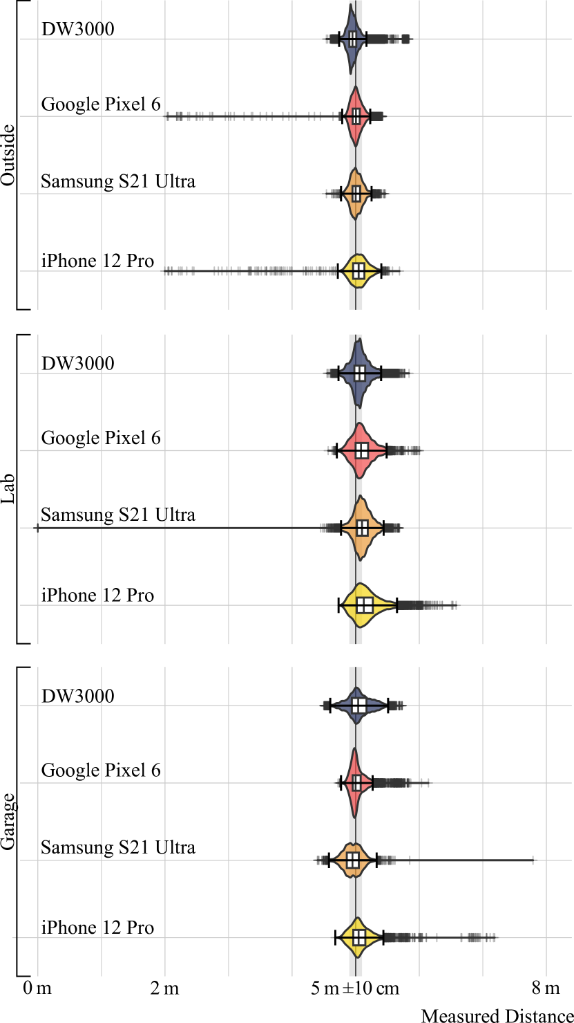
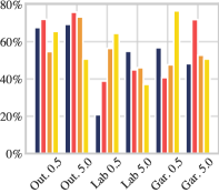
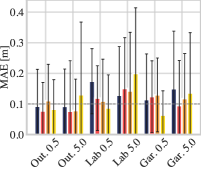
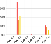
Figure 12 plots the results of all measurements conducted at a distance. The plot is a combination of a violin plot and a box plot. We can see that most measurements are in proximity to the expected distance. Interestingly, the DUTs have shown large maximum errors. The Samsung Galaxy reduced the distance by up to , the Apple iPhone, and the Google Pixel by up to .
To evaluate the accuracy we define a range of the actual distance as accurate. An error of is advertised by chip manufacturers [3, 51]. Since the antenna is in the intersection of the rotation axes, movements of GWEn did not alter the distance. In Figure 12 the accuracy range is marked in gray. Figure 13(a) shows the percentage of accurate measurements. The accuracy ranges between and . Depending on the environment and distance, for a given device it can vary by up to .
Although the maximum errors can be large, Figure 13(b) shows that the mean absolute error (MAE) is less than , while the mean standard deviation (SD) is below for each measurement series. Figure 13(c) plots the percentage of failed measurements. A failed measurement is a position ( & ) of GWEn at which less than measurements were recorded in . A high failure rate translates into an unreliable UWB system.
Figure 14 shows a polar plot of a full base rotation () with the arm position fixed at . The remote device is placed at the angle of at a distance of . This plot corresponds to the setup shown in Figure 8.
VI-C Outside
This section covers our measurements conducted outside, on soil ground without any obstructions that could reflect the measurements. Missing surfaces to reflect the signals influence the measurements. At larger distances, the signals that are directed away from the remote device, do not reach it or the DUT cannot receive signals while the antenna is directed away from the remote device.
Accuracy
For most devices, the measurements outside resulted in the highest percentage of accurate measurements. This likely stems from the minimal interference and lack of obstacles that could have produced reflections. As visible in Figure 14(a) there is a correlation between the base position and the accuracy. Overall the Google Pixel 6 Pro had the best accuracy, followed by the DW3000, which created clearly visible outliers at several positions.
Measurement error
The MAE and SD of most devices are low and close to the goal of . Only the iPhone has a largely increased SD of at the distance. All other devices produce similar results. Moreover, the Google Pixel and the iPhone also produced outliers of up to . Previous research [39] expected these failures only in a multipath environment, but our measurements show that they can also occur without reflections.
Reliability
Interestingly, we can see very large failure rates on all smartphones at a distance of . By rotating the base () of GWEn the DUT’s antenna will point away from the remote device when . The signals are no longer strong enough to reach both devices. The effect is the strongest, when the arm is at and the phone internals are shielding the UWB antenna. In Figure 14(a) failed measurements are not plotted. The Google Pixel is the most unreliable here and fails to measure at of all positions. At the distance this effect was not visible. The DWM3000 has an exposed antenna and therefore does not fail to receive signals at any position.
VI-D Lab
In this section, we cover the results of the measurements conducted in our lab. This location had the most surfaces and reflecting areas, i.e., whiteboards and screens, in our measurement series. This resulted in very good reliability but reduced accuracy.
Accuracy
Depending on the distance and the device, the accuracy in this environment varies a lot. The DW3000 has an accuracy of at , while the Samsung reaches . Figure 14(b) shows how the accuracy on all smartphones is worse when . Most outliers are distance enlargements due to longer paths caused by reflections of the signals. Only the Samsung Smartphone measured reduced distances of and .
Measurement error
The Apple iPhone has the largest MAE of , which is also visible in Figure 14(b). The iPhone may select the wrong first path and therefore, increase or even decrease the measured distance. This behavior also aligns with a previously presented attack on Apple’s U1 UWB chip, which has shown that the iPhone can be tricked into accepting an attacker’s pulse as the first path and, therefore, producing shortened distance measurements [14].
However, this error is only present at larger distances. The same characteristic that blocked the signals outside, is now resulting in increased errors.
Reliability
The strong multipath effects in this environment result in fewer failed measurements (see Figure 13(c)). The Google Pixel has the highest failure rate of all other devices are able to measure reliably at all positions. At all devices measured reliably.
VI-E Parking garage
The public parking garage had over twenty cars on one level. The results of these measurements are presented in this section. The remote devices were placed next to a parked car. As always, both devices were placed in LoS. Multipath effects occur in this environment, but they are less common than in the lab environment.
Accuracy
The overall accuracy of all smartphones increased compared to the lab environment. The Google Pixel performs best at reaching an accuracy of . All other devices performed similarly and were accurate in of the measurements. For the iPhone is the most accurate with of accurate measurements.
Measurement error
The measurement error of all devices is less than in an environment where this technology is already deployed in a PKE system for modern cars. Additionally, we did not measure large negative outliers on any device. All smartphones produced distance enlargements and Samsung Galaxy measured a distance of up to .
Reliability
The reliability in this environment is good, with less than of failed measurements on any device and distance. Since the garage had a concrete roof, concrete floor and many cars around, the reflections of the UWB signal were able to reach the remote device. Similar to the outside environment, the smartphone internals block the signal transmission and the environment did not provide enough reflections to allow for multipath transmissions. In practice, this means, that smartphones might need several attempts to measure the distance to a car from a larger distance, but should not fail.
In Figure 14(c) we can see fewer failed ranging measurements as in the outdoor environment. At base rotations of , several measurements failed. Similarly to the outside environment, the smartphone internals block the signal transmission and the environment did not provide enough reflections to allow for multipath transmissions.
VI-F Influence of the remote device
As mentioned in Section V-C, the iPhone and Android smartphones are not compatible to perform UWB distance ranging with each other. Fortunately, Android devices from different manufacturers are compatible, and we, therefore, performed all measurements of the Google Pixel as a DUT also with a Samsung Galaxy as the remote device.
Unfortunately, we were not able to measure with a Google Pixel as a remote device in the outdoor environment. This was supposed to be our last measurement series, but the phones were not able to connect at all over UWB. A software reset of the devices did not result in any change. Therefore, our outside measurements of the Google Pixel purely use a Samsung Galaxy as the remote device.
We measured a consistent improvement in all areas when using the Samsung Galaxy as the remote device. The measurements failed less often and the accuracy increased by to . The MAE is slightly worse in this setting and outliers were similar. The remote device has an influence on the overall measurement performance. The Samsung Galaxy might have a stronger antenna, and therefore, reduces the failure rate.
VII Discussion
Our measurements have shown that the advertised accuracy of is not reproducible. Even when both UWB antennas were directed at each other a MAE of more than is normal. Additionally, all smartphones are unreliable in certain positions and environments. They failed to measure the distance at positions directed away from the remote device. However, the overall performance is promising: The MAE is below and at shorter distances, the devices succeeded to measure the distance at every position we evaluated. In this section, we detail how these results may affect UWB-based entry systems and which considerations have to be taken when implementing such systems.
VII-A Overall performance
Accuracy and Reliability
Our measurements identified that internal components of a smartphone shield the low power UWB signals, resulting in strong directional differences. In a real-world scenario, this influences the overall user experience: Depending on the position of a smartphone in a pocket or bag, the device is not able to perform UWB ranging. If successful, measurements can have an increased distance by several meters because the devices rely on reflected signals, which travel a longer path. These issues can delay the time until a distance-based action is triggered, e.g., when approaching UWB–cars with iPhone support have the ability to activate their headlights in order to welcome the driver [52]. In addition, future smart home interactions might fail to recognize that the user is present and as a result turn off lights or heating in these areas. At short distances we measured a high reliability of all devices and a MAE of less than .
Software support
All smartphones, which we evaluated offer an API to perform UWB ranging to other smartphones or IoT devices. Apple was the first manufacturer to open up their ranging system to FiRa compatible chipsets (e.g., Qorvo and NXP)[19]. Google also integrated an Android-wide API for UWB, which should also be compatible with FiRa chips [49]. Unfortunately, the documentation lacks important parts and Google does not disclose how to perform ranging with non-Android devices. Moreover, the stability of the API varies largely. To start ranging successfully it was required to perform around ten attempts on all Android devices and finally, our Google Pixel devices suddenly failed to perform UWB ranging completely.
Overall, the user experience may be weakened, but the mean measured distances over ten or more consecutive measurements have proven to normalize the results. If the software issues are resolved, the current consumer-market implementations are in a good shape to be used for distance estimations in most smart home scenarios and for secure entry systems, if some precautions are made (see Section VII-D).
VII-B Comparison to previous research
Several researchers analyzed the accuracy and ranging errors of different UWB devices. None of these devices were actual consumer hardware, most of them focused on the Decawave (now Qorvo) devices. In this section, we compare the results of our research on consumer hardware and the Qorvo DW3000 with previous results.
DW1000
Malajner et al. [33] analyzed the ranging accuracy in LoS of the DW1000, the predecessor of the DW3000. Depending on the configuration of the chip, they identified a root mean squared error (RMSE) between and for uncalibrated devices. For calibrated devices, the RMSE was lower at a range of .
BeSpoon phone
Jimenez et al. [34] compared the BeSpoon phone666The BeSpoon phone was a prototype hardware demonstrating that it is feasible to implement UWB in smartphones. with the DW1000. In LoS measurements, the BeSpoon reached a mean error of and a SD of . In Non-Line-of-Sight (NLoS), the mean error was and the SD . Using the mean error is non-optimal as the errors can be positive or negative, which is why we measure the MAE in this work. When comparing the mean standard deviation over all our measurements, the DW3000 had , the Pixel , the Galaxy S21 Ultra , and the iPhone . We can see that modern consumer hardware operates at similar levels, as our measurements include both NLoS (blocked by smartphone internals) and LoS scenarios.
DW3000 and 3dB Access
Fluearto et al. [36] compared the DW3000 with a UWB–LRP development kit from 3db Access. In LoS, the mean error of the 3dB Access device was whereas the mean error of the DW3000 was . They measured SDs of and , respectively. In NLoS, the mean error increased to and . The SD also increased to and . Our results are in the same range as the ones measured by Fluearto et al.
DW3000 in motion
Tiemann et al. [37] performed an experimental evaluation of the DW3000 while walking through a storage hall with many obstructions. Overall, the measurement errors are less than throughout the whole measurement series. In our measurement campaign, the DW3000 performed similarly well with only a few larger outliers. Our measurements on consumer hardware, however, had larger outliers reaching multiple meters.
VII-C Security implications
The already mentioned shielding combined with reflections resulted in an enlarged measured distance in different environments. At a distance of , the measured distances on all smartphones resulted in range of to . An enlargement of the measured distance can affect the convenience of a PKE system, but not the security.
The Samsung devices show a lower MAE and better accuracy than the iPhones, but the Samsung devices repeatedly measured a distance of in the Lab environment. Such strong reductions can affect the security of UWB-based entry systems. The Apple iPhone and Google Pixel also created distance reductions of up to when ranging outside. This might not be enough to provoke the unlock action from a distance. However, these reductions are unexpected, since the devices had no interference and should, therefore, be able to measure accurately.
None of these distance reductions have been consistent and happened as outliers. Following our recommendations in Section VII-D mitigates these problems.
Previous research presented an attack on iPhones in a LoS setup that resulted in reproducible distance reductions [14]. It is to be researched if the attack’s success-rate increases when both devices are no longer in LoS, use different orientations as used in our experimental setup, or operate in environments with strong interferences. Especially on the iPhone, we discovered that the SD increases when the device is no longer directed to its peer (see Figure 14(b)).
VII-D Recommendations for implementing a secure passive keyless entry system
UWB is the most promising technology when it comes to secure distance measurements at a consumer hardware level. Known attacks only have a low success rate and in general, the produced ranging errors are less than . Nevertheless, there are important things to consider when implementing such a system.
Since this technology directly interferes with the real world by sending pulse-based signals, any obstructions, the positioning of the devices, and other wireless devices can influence the accuracy of distance measurements. This has been demonstrated by our study and previous work [37].
To implement a secure entry system we give four recommendations:
VII-D1 Two-way ranging
The implementation should always use the IEEE 802.15.4z Double-Sided Two-Way Ranging (DS-TWR) ranging algorithm. With DS-TWR ranging, potential clock drifts are eliminated, and both sides calculate a distance measurement without the necessity to send the measured distance from one device to the other. If a smartphone sends a command to open to a smart lock, the measured distance should also be validated by the lock before granting access.
VII-D2 Use mean values
Before a trusted distance can be estimated, at least ten to ranging cycles should be performed. Using a sliding window of ten measurements it is possible to calculate a mean distance over all measured distances. Only the mean value should be used for the decision of granting access or not. In a security context, the device should never perform the distance-based action on the first measurement that is in the desired range. Our study has shown that accidental distance reductions of to can happen. According to our tests, in most scenarios, ten measurements can be performed in less than .
VII-D3 Drop clearly wrong measurements
When placing two devices right next to each other it is possible to create negative values for a distance measurement. These values are very rare and should not be considered in any parts of the algorithm.
VII-D4 Detect potential attacks
The only currently known attack on UWB HRP IEEE 802.15.4z systems has a low success rate and cannot be controlled accurately [14]. An iPhone under attack has reported several measurements with up to . Therefore, negative values should also be counted to detect potential attacks on an UWB entry system. If reported distances fluctuate strongly or the system detects several strongly negative values, the distance measurement should be suspended, and the user should be informed.
VIII Conclusion
In our study, we evaluated UWB distance measurements of three modern smartphones with UWB and a development kit from Qorvo with a focus on accuracy and reliability. We designed, built and used a novel measurement setup called GWEn to evaluate changes in the antenna position on performed measurements.
Our results have shown that in most cases the measured distance is less accurate than advertised by the manufacturers[3, 2]. Nevertheless, the devices produce errors in a reasonable range with a mean absolute error of less than . The results are on average good enough to perform distance estimation and to decide whether a smart lock or PKES of a car should open. However, all smartphones shared the weakness that measurements can fail depending on the position of the antenna, e.g., when the antenna no longer faces the direction of the remote device. These issues decrease the user experience and may lower the adoption of people. From our results, we derived four recommendations to improve the security of PKE systems.
Acknowledgment
This work has been funded by the German Federal Ministry of Education and Research and the Hessen State Ministry for Higher Education, Research and the Arts within their joint support of the National Research Center for Applied Cybersecurity ATHENE and by the LOEWE initiative (Hesse, Germany) within the emergenCITY center.
References
- [1] BMW AG, “BMW announces BMW Digital Key Plus with Ultra-Wideband technology coming to the BMW iX.” 01 2021. [Online]. Available: https://www.press.bmwgroup.com/global/article/detail/T0324128EN/bmw-announces-bmw-digital-key-plus-with-ultra-wideband-technology-coming-to-the-bmw-ix?language=en
- [2] NXP Semiconductors, “SR040 Ultra-Wideband Transceiver - Product Short Data Sheet,” p. 14, 2021.
- [3] Qorvo Inc., “DW3000 Data Sheet V1.3,” 2020. [Online]. Available: https://www.qorvo.com/products/d/da008142
- [4] P. Staat, K. Jansen, C. Zenger, H. Elders-Boll, and C. Paar, “Analog Physical-Layer Relay Attacks with Application to Bluetooth and Phase-Based Ranging,” in Proceedings of the 15th ACM Conference on Security and Privacy in Wireless and Mobile Networks, ser. WiSec ’22. New York, NY, USA: Association for Computing Machinery, May 2022, pp. 60–72. [Online]. Available: https://doi.org/10.1145/3507657.3528536
- [5] O. A. Ibrahim, A. M. Hussain, G. Oligeri, and R. Di Pietro, “Key is in the Air: Hacking Remote Keyless Entry Systems,” in Security and Safety Interplay of Intelligent Software Systems, ser. Lecture Notes in Computer Science, B. Hamid, B. Gallina, A. Shabtai, Y. Elovici, and J. Garcia-Alfaro, Eds. Cham: Springer International Publishing, 2019, pp. 125–132.
- [6] S. Krollmann, A. Heinrich, F. Putz, and M. Hollick, “GWEn - Gimbal based platform for Wireless Evaluation,” Jul. 2022. [Online]. Available: https://sandbox.zenodo.org/record/1107222
- [7] A. Heinrich, S. Krollmann, F. Putz, and M. Hollick, “Dataset of UWB ranging measurements with smartphones,” Mar. 2023. [Online]. Available: https://doi.org/10.5281/zenodo.7702153
- [8] IEEE Standard for Information technology– Local and metropolitan area networks– Specific requirements– Part 15.4: Wireless Medium Access Control (MAC) and Physical Layer (PHY) Specifications for Low-Rate Wireless Personal Area Networks (WPANs): Amendment 1: Add Alternate PHYs, 2007.
- [9] IEEE Standard for Low-Rate Wireless Networks, 2020.
- [10] IEEE Standard for Low-Rate Wireless Networks–Amendment 1: Enhanced Ultra Wideband (UWB) Physical Layers (PHYs) and Associated Ranging Techniques, 2020.
- [11] Qorvo Inc., “DW3000 Device Driver Application Programming Interface (API) Guide,” 2019.
- [12] M. Flury, M. Poturalski, P. Papadimitratos, J.-P. Hubaux, and J.-Y. Le Boudec, “Effectiveness of distance-decreasing attacks against impulse radio ranging,” in Proceedings of the Third ACM Conference on Wireless Network Security, ser. WiSec ’10. New York, NY, USA: Association for Computing Machinery, Mar. 2010, pp. 117–128. [Online]. Available: https://doi.org/10.1145/1741866.1741887
- [13] M. Poturalski, M. Flury, P. Papadimitratos, J.-P. Hubaux, and J.-Y. Le Boudec, “The cicada attack: Degradation and denial of service in IR ranging,” in 2010 IEEE International Conference on Ultra-Wideband. Nanjing, China: IEEE, Sep. 2010, pp. 1–4. [Online]. Available: http://ieeexplore.ieee.org/document/5616900/
- [14] P. Leu, G. Camurati, A. Heinrich, M. Roeschlin, C. Anliker, M. Hollick, S. Capkun, and J. Classen, “Ghost peak: Practical distance reduction attacks against HRP UWB ranging,” in 31st USENIX Security Symposium (USENIX Security 22). Boston, MA: USENIX Association, Aug. 2022, pp. 1343–1359. [Online]. Available: https://www.usenix.org/conference/usenixsecurity22/presentation/leu
- [15] The U1 chip in the iPhone 11 is the beginning of an Ultra Wideband revolution. Six Colors. [Online]. Available: https://sixcolors.com/post/2019/09/the-u1-chip-in-the-iphone-11-is-the-beginning-of-an-ultra-wideband-revolution/
- [16] STMicroelectronics N.V., “History – UWB,” 2020. [Online]. Available: https://bespoon.xyz/team/
- [17] Samsung Electronics Inc, “Samsung Unveils Five New Power Devices in the Galaxy Ecosystem To Empower Your Work and Play,” Aug. 2020. [Online]. Available: https://news.samsung.com/us/samsung-unveils-five-devices-unpacked-galaxy-ecosystem-galaxy-note20-ultra-galaxy-z-fold2/
- [18] Qorvo Inc., “Qorvo Delivers Ultra-Wideband in Google Pixel 6 Pro.” [Online]. Available: https://www.qorvo.com/newsroom/news/2021/qorvo-delivers-ultra-wideband-in-google-pixel-6-pro
- [19] Nearby Interaction — Apple Developer Documentation. [Online]. Available: https://developer.apple.com/documentation/nearbyinteraction
- [20] Mobile Knowledge, “MK UWB Kit product brief,” Part of the documentation provided with the MK UWB Kit.
- [21] “FiRa Consortium.” [Online]. Available: https://www.firaconsortium.org/
- [22] Car Connectivity Consortium – An organization advancing global technologies for smartphone-to-car connectivity solutions. [Online]. Available: https://global-carconnectivity.org/
- [23] “Car Connectivity Consortium Publishes Digital Key Release 3.0,” Car Connectivity Consortium. [Online]. Available: https://carconnectivity.org/press-release/car-connectivity-consortium-publishes-digital-key-release-3-0/
- [24] ING Group, “Point and pay,” Jul. 2022. [Online]. Available: https://www.ing.com/Newsroom/News/Point-and-pay.htm
- [25] NXP Semiconductors, “NXP Collaborates with ING and Samsung to Pilot Industry’s First UWB-Based Peer-to-Peer Payment Application.” [Online]. Available: https://www.nxp.com/pages/:NW-NXP-COLLABORATES-WITH-ING-AND-SAMSUNG-TO-PI
- [26] Samsung Electronics Inc, “Introducing the New Galaxy SmartTag+: The Smart Way to Find Lost Items,” Apr. 2021. [Online]. Available: https://news.samsung.com/us/introducing-the-new-galaxy-smarttag-plus/
- [27] Apple Inc., “Find your keys, backpack, and more with AirTag - Apple Support,” Sep. 2022. [Online]. Available: https://support.apple.com/en-us/HT210967
- [28] A. I. Shaik, “Samsung Wallet gets access to world’s first UWB-based smart door lock,” Nov. 2022. [Online]. Available: https://www.sammobile.com/news/samsung-wallet-worlds-first-uwb-digital-home-key/
- [29] V. Niculescu, D. Palossi, M. Magno, and L. Benini, “Energy-efficient, Precise UWB-based 3-D Localization of Sensor Nodes with a Nano-UAV,” IEEE Internet of Things Journal, 2022.
- [30] L. Flueratoru, S. Wehrli, M. Magno, E. S. Lohan, and D. Niculescu, “High-Accuracy Ranging and Localization With Ultrawideband Communications for Energy-Constrained Devices,” IEEE Internet of Things Journal, vol. 9, no. 10, pp. 7463–7480, May 2022.
- [31] Y. Cao, C. Chen, D. St-Onge, and G. Beltrame, “Distributed TDMA for Mobile UWB Network Localization,” IEEE Internet of Things Journal, vol. 8, no. 17, pp. 13 449–13 464, Sep. 2021.
- [32] D. Feng, C. Wang, C. He, Y. Zhuang, and X.-G. Xia, “Kalman-Filter-Based Integration of IMU and UWB for High-Accuracy Indoor Positioning and Navigation,” IEEE Internet of Things Journal, vol. 7, no. 4, pp. 3133–3146, Apr. 2020.
- [33] M. Malajner, P. Planinšič, and D. Gleich, “UWB ranging accuracy,” in 2015 International Conference on Systems, Signals and Image Processing (IWSSIP), Sep. 2015, pp. 61–64.
- [34] A. Jiménez and F. Seco, “Comparing Decawave and Bespoon UWB location systems: Indoor/outdoor performance analysis,” in 2016 International Conference on Indoor Positioning and Indoor Navigation (IPIN), Oct. 2016, pp. 1–8.
- [35] A. R. Jiménez Ruiz and F. Seco Granja, “Comparing Ubisense, BeSpoon, and DecaWave UWB Location Systems: Indoor Performance Analysis,” IEEE Transactions on Instrumentation and Measurement, vol. 66, no. 8, pp. 2106–2117, Aug. 2017.
- [36] L. Flueratoru, S. Wehrli, M. Magno, and D. Niculescu, “On the Energy Consumption and Ranging Accuracy of Ultra-Wideband Physical Interfaces,” in GLOBECOM 2020 - 2020 IEEE Global Communications Conference, Dec. 2020, pp. 1–7.
- [37] J. Tiemann, J. Friedrich, and C. Wietfeld, “Experimental Evaluation of IEEE 802.15.4z UWB Ranging Performance under Interference,” Sensors, vol. 22, no. 4, p. 1643, Jan. 2022. [Online]. Available: https://www.mdpi.com/1424-8220/22/4/1643
- [38] R. Juran, P. Mlynek, M. Stusek, P. Masek, M. Mikulasek, and A. Ometov, “Hands-On Experience with UWB: Angle of Arrival Accuracy Evaluation in Channel 9,” in 2022 14th International Congress on Ultra Modern Telecommunications and Control Systems and Workshops (ICUMT). Valencia, Spain: IEEE, Oct. 2022, pp. 45–49. [Online]. Available: https://ieeexplore.ieee.org/document/9943504/
- [39] M. Singh, M. Roeschlin, E. Zalzala, P. Leu, and S. Čapkun, “Security analysis of IEEE 802.15.4z/HRP UWB time-of-flight distance measurement,” in Proceedings of the 14th ACM Conference on Security and Privacy in Wireless and Mobile Networks, ser. WiSec ’21. New York, NY, USA: Association for Computing Machinery, Jun. 2021, pp. 227–237. [Online]. Available: https://doi.org/10.1145/3448300.3467831
- [40] G. Boussatour, P.-Y. Cresson, B. Genestie, N. Joly, and T. Lasri, “Dielectric Characterization of Polylactic Acid Substrate in the Frequency Band 0.5–67 GHz,” vol. 28, no. 5, pp. 374–376.
- [41] Prusa Research a.s., “Original Prusa i3 MK3S+.” [Online]. Available: https://www.prusa3d.com/category/original-prusa-i3-mk3s/
- [42] Qorvo Inc., “DWM3000 - Qorvo.” [Online]. Available: https://www.qorvo.com/products/p/https//www.qorvo.com/products/p/DWM3000
- [43] Amaldev, “UWB: The Tech Behind Apple AirTags,” Apr. 2021. [Online]. Available: http://amaldev.blog/uwb-the-tech-behind-apple-airtags/
- [44] iFixit, “Samsung Galaxy S21 Ultra Teardown,” Mar. 2021. [Online]. Available: https://www.ifixit.com/Teardown/Samsung+Galaxy+S21+Ultra+Teardown/141188
- [45] T. Dixon, “iPhone 12 and 12 Pro Teardown,” Oct. 2020. [Online]. Available: https://www.ifixit.com/Teardown/iPhone+12+and+12+Pro+Teardown/137669
- [46] Hugh Jeffreys, “Pixel 6 Pro Teardown and Repair Assessment - Serialisation With A Twist,” Nov. 2021. [Online]. Available: https://www.youtube.com/watch?v=oO3MNKfaars
- [47] Apple Inc., “Nearby Interaction — Apple Developer Documentation.” [Online]. Available: https://developer.apple.com/documentation/nearbyinteraction
- [48] Google Inc., “How we’re making it easier to share files with nearby devices,” Sep. 2022. [Online]. Available: https://blog.google/products/android/better-together-nearby-share/
- [49] Google Inc, “Ultra-wideband communication,” Dec. 2022. [Online]. Available: https://developer.android.com/guide/topics/connectivity/uwb
- [50] Apple Inc., “Profiles and Logs - Bug Reporting - Apple Developer.” [Online]. Available: https://developer.apple.com/bug-reporting/profiles-and-logs/
- [51] AMOSENSE Co., Ltd, Amotech SR040 Module Datasheet v0.9, Jun. 2021.
- [52] A. Inc. Explore UWB-based car keys - WWDC21 - Videos. Apple Developer. [Online]. Available: https://developer.apple.com/videos/play/wwdc2021/10084/
- UWB
- Ultra-Wide Band
- HRP
- High-Rate Pulse Repetition Frequency
- PKES
- Passive Keyless Entry and Start
- PKE
- Passive Keyless Entry
- LRP
- Low-Rate Pulse Repetition Frequency
- TWR
- Two-Way Ranging
- DS-TWR
- Double-Sided Two-Way Ranging
- SS-TWR
- Single-Sided Two-Way Ranging
- TDOA
- Time Difference of Arrival
- SFD
- Start of Frame Delimiter
- PRF
- Pulse-Repetition Frequency
- PSD
- Power Spectral Density
- ToA
- Time-of-Arrival
- ToF
- Time-of-Flight
- LoS
- Line-of-Sight
- NLoS
- Non-Line-of-Sight
- STS
- Scrambled Timestamp Sequence
- SFD
- Start-of-Frame Delimiter
- MitM
- Machine-in-the-Middle
- NI
- Nearby Interaction
- BLE
- Bluetooth Low Energy
- ED/LC
- Early Detect/Late Commit
- BPSK
- Binary Phase Shift Keying
- BPM
- Burst-Position Modulation
- RSSI
- Received Signal Strength Indicator
- GWEn
- Gimbal-based platform for Wireless Evaluation
- DUT
- device under test
- ANI
- Apple Nearby Interaction
- FiRa
- Fine Ranging Consortium
- CCC
- Car Connectivity Consortium
- AoA
- angle of arrival
- API
- application programming interface
- PLA
- polylactic acid
- CDF
- cumulative Distribution Function
- MAE
- mean absolute error
- SD
- standard deviation
- RKS
- Remote Keyless System
- NFC
- near-field communication
- IoT
- Internet of Things
- PRF
- pulse repetition frequency
- RMSE
- root mean squared error
![[Uncaptioned image]](/html/2303.11220/assets/figures/biographies/aheinrich.jpg) |
Alexander Heinrich received the B.Sc., M.Sc. degrees from the Technical University of Darmstadt, Darmstadt, Germany, in 2017 and 2019, respectively. He is a Ph.D. candidate with the Secure Mobile Networking Lab, Technical University of Darmstadt. His research is on the security and privacy of wireless protocols with a focus on location-aware systems. Mr. Heinrich received several best demo awards and the best paper award at the ACM Conference on Security and Privacy in Wireless and Mobile Networks. |
![[Uncaptioned image]](/html/2303.11220/assets/figures/biographies/skrollmann.jpg) |
Sören Krollmann received the M.Sc. degree from Technical University of Darmstadt, Darmstadt, Germany in 2022. He worked as a scientific assistant with the Secure Mobile Networking Lab, Technical University of Darmstadt. His research focused on distance measurement using Ultra-Wide Band technology. Mr. Krollmann currently works in industry as a cyber security consultant and supports customers on their way to more security. |
| Florentin Putz received the B.Sc. and M.Sc. degrees from the Technical University of Darmstadt, Darmstadt, Germany, in 2016 and 2019, respectively. He is a Ph.D. candidate with the Secure Mobile Networking Lab, TU Darmstadt. His research focuses on deployable and usable security mechanisms for smartphones and the Internet of Things. Mr. Putz received several awards, including the Best Student Award from TU Darmstadt’s electrical engineering department as well as the KuVS Award 2020 for the best master’s thesis in communications and distributed systems in Germany. |
![[Uncaptioned image]](/html/2303.11220/assets/figures/biographies/mhollick.jpg) |
Matthias Hollick received his Ph.D. degree from TU Darmstadt, Darmstadt, Germany, in 2004. He is currently heading the Secure Mobile Networking Lab, Computer Science Department, Technical University of Darmstadt. He has been researching and teaching at TU Darmstadt, Universidad Carlos III de Madrid, Getafe, Spain, and the University of Illinois at Urbana–Champaign, Champaign, IL, USA. His research focus is on resilient, secure, privacy-preserving, and quality- of-service-aware communication for mobile and wireless systems and networks. |