NeTO:Neural Reconstruction of Transparent Objects with
Self-Occlusion Aware Refraction-Tracing
Abstract
We present a novel method called NeTO, for capturing the 3D geometry of solid transparent objects from 2D images via volume rendering. Reconstructing transparent objects is a very challenging task, which is ill-suited for general-purpose reconstruction techniques due to the specular light transport phenomena. Although existing refraction-tracing-based methods, designed especially for this task, achieve impressive results, they still suffer from unstable optimization and loss of fine details since the explicit surface representation they adopted is difficult to be optimized, and the self-occlusion problem is ignored for refraction-tracing. In this paper, we propose to leverage implicit Signed Distance Function (SDF) as surface representation and optimize the SDF field via volume rendering with a self-occlusion aware refractive ray tracing. The implicit representation enables our method to be capable of reconstructing high-quality reconstruction even with a limited set of views, and the self-occlusion aware strategy makes it possible for our method to accurately reconstruct the self-occluded regions. Experiments show that our method achieves faithful reconstruction results and outperforms prior works by a large margin. Visit our project page at https://www.xxlong.site/NeTO/.
1 Introduction
Reconstructing 3D models of real-world objects has been one of the longstanding problems. It has been researched for decades in computer vision and graphics, which boosts the development of many applications, such as augmented reality, automatic driving, and robots. However, existing general-purpose multi-view reconstruction methods [15, 16, 38, 46] are only suitable for opaque objects whose surfaces are approximately Lambertian, and few of them can tackle transparent objects. The light paths passing through transparent objects are extremely complex and involve refractions and reflections.
Recently, some state-of-the-art methods have been proposed to reconstruct solid transparent objects in a non-intrusive manner, capturing refraction-tracing consistency with specially designed hardware systems, and have produced impressive results. This is achieved by optimizing correspondences between camera rays and locations on the background monitor [22] or enforcing consistency between camera rays and refracted rays with a rotating background monitor [51]. However, those methods either adopt point cloud [51] or mesh [22] as surface representation, and the explicit representations are difficult to be optimized. As a result, the methods usually require a large number of views as input for optimization. Without enough images as input, the methods easily fail to reconstruct faithful geometry due to unstable optimization (see Figure 1).
More importantly, a critical issue still remains ignored, i.e., how to tackle the self-occluded parts of the objects. The widely-used refraction-tracing consistency assumes that a camera ray is only refracted twice (upon entering and upon exiting) on the object surfaces when the ray passes through a transparent object. However, the assumption is not always true when a camera ray passes through the self-occluded parts where the ray will be refracted by surfaces more than twice. As a result, mistakenly enforcing the refraction-tracing consistency on the self-occluded parts will unavoidably introduce errors in the optimization of reconstruction, which is a bottleneck to further enhance the reconstructed geometries.
In this work, we propose a novel method, called NeTO, for reconstructing high-quality 3D geometry of solid transparent objects. In contrast to prior works [22], we adopt implicit Signed Distance Function (SDF) as surface representation and leverage volume rendering [46] to enforce the refraction-tracing consistency. Moreover, we propose a simple but effective strategy to detect the self-occluded parts and avoid mistakenly enforcing constraints on these regions. The key idea is that we leverage the law of reversibility, that is, If the direction of a light beam is reversed, despite the number of times the beam is reflected or refracted, it will follow the same path, to identify whether a camera ray is reversible or not upon the assumption that the ray is refracted exactly twice.
To validate our method, we conduct experiments on DRT [22] dataset and our collected data with full views setting and various sparse views settings. The sparse setting selects one view from every n consecutive camera index, i.e., , where is termed as Sparsity. The extensive experiments show that our method enables the high-quality reconstruction of transparent objects and outperforms the previous methods. Our contributions can be summarized as follows:
-
•
A novel neural surface reconstruction system is adopting implicit SDF as a representation for reconstructing transparent objects, thus enabling robust reconstruction optimization.
-
•
A self-occlusion aware refraction-tracing strategy is introduced to accurately enforce the constraint, making it possible to recover geometries with fine details.
-
•
Experimental results show that our method achieves SOTA results compared to prior works.
2 Related Work
2.1 Environment matting
Environment matting is introduced by [58], which extracts the environment matte and silhouettes from a series of projected horizontal and vertical stripe patterns. Subsequent works have been extended to multiple cameras [7], natural images [3, 50], wavelet domains [31], and frequency domain [34]. Meanwhile, it can be combined with compressive sensing theory [9] to reduce the number of used images. Unlike the above method, we adopt environment matting to capture environment matte and object masks and optimize the object geometries to fit them.
2.2 Transparent Object Reconstruction
Recovering the 3D geometry of transparent objects is a longstanding challenging problem [13]. To solve this difficult task, many works leverage specially designed hardware setups to provide more information encoding object geometries, including polarization [8, 12, 25, 40], tomography [43], a moving point light source [4, 26], light field probes [49] and gray-coded patterns [22, 35, 51]. Some methods [39, 56] target the reconstruction of transparent objects with refractive or mirror-like surfaces. Other methods, including ours, focus on solid transparent objects where most camera rays will refract on the surfaces twice. To reconstruct the geometry of transparent objects, there are many types of correspondences proposed, like multi-view ray-ray correspondences [35, 44, 51], and ray-location correspondences [22]. DRT [22] proposed to extract per-view ray-location correspondences by using the EnvMatt algorithm [58], and utilize the differentiable rendering for progressively optimizing explicit meshes. Xu et al. [52] introduced ray-cell correspondence for reconstructing the full mode under natural light. Besides, Shao et al. [40] adopted polarimetric cues to reconstruct the full model of transparent objects [40].
Recently, data-driven-based methods have shown remarkable achievements in estimating the depth and normal maps of transparent objects [14, 37, 41]. Li et al. [14] first predicted the rough geometry of the transparent objects and then leveraged Pointnet++ [33] to further refine the rough geometry. However, due to the domain gap between the synthetic and real data, Li et al. [14] failed to reconstruct real objects unseen in its training dataset. More recently, Bemana et al. [2] leveraged NeRF for novel view synthesis of transparent objects and showed good performance to render novel views. However, since it targets novel view synthesis rather than reconstruction, it’s difficult to extract reliable geometry from the method. Unlike the above methods, We leverage volume rendering to simulate the refraction-tracing path for geometry optimization.
2.3 Neural Implicit Representation
Existing 3D representations can be roughly divided into four categories voxel-based representations [6], point-based representations [1, 10], mesh-based representations [22, 45], and neural implicit representations [5, 23, 29, 36]. Recently, implicit neural representations have been applied to a variety of applications, including novel view synthesis [24, 57], camera pose estimation [17, 48], human [18, 32] and multi-view 3D reconstruction [11, 19, 20, 27, 28, 42, 46, 47, 54, 55], and achieved impressive successes. Recent research has shown that reconstructed results using implicit neural representation often produce higher quality than other 3D representations.
For the task of 3D reconstruction from 2D images, some works combine implicit neural representation with surface rendering techniques. These works typically require additional constraints for optimization, such as object masks. Moreover, inspired by the seminal work NeRF [48], more recent works apply volume rendering techniques to optimize the implicit neural representation encoded geometry. In this work, we adopt an implicit signed distance function as geometry representation and leverage the volume rendering technique proposed in NeuS [46] to optimize the geometries with the ray-location correspondences [22, 35, 51].
3 Method
3.1 Overview
We aim to reconstruct the surfaces of a solid transparent object from a set of posed object masks and the correspondences between the camera view rays and locations on the background under each viewpoint. We propose to adopt an implicit Signed Distance Function (SDF) as surface representation and leverage volume rendering [46] to enforce the refraction-tracing consistency, which enables stable and robust optimization. Moreover, we propose a simple but effective strategy to identify the rays passing through self-occluded parts and then exclude these rays during optimization to avoid mistakenly enforcing refraction-tracing consistency.
3.2 Preliminaries
Object capture setup. To reconstruct the transparent objects, we adopt the similar object capture system proposed in [22, 51]. The system consists of a static LCD monitor, a turntable, and a camera. The monitor displays horizontal and vertical stripe patterns that form a Gray-coded background, and is placed behind the object and the camera. The transparent object is placed on the turntable, which is rotated in data acquisition to provide the static camera with multiple views of the object. The silhouette mask information and environment matte can be extracted from the patterns displayed on the monitor.
Refraction-tracing consistency. For general objects, feature points of the input images are extracted to establish correspondences for 3D reconstruction. However, for transparent objects, it’s difficult to extract reliable feature points to establish correspondences, so the prior works and ours leverage the environment matting technique to establish the relationship between object geometry and the observed images. As shown in Figure 3, a ray shooting from the camera center passes through the transparent object, which refracts twice on the object surfaces and then hits on the monitor at point . Since the gray-coded patterns are known, we can calculate the exact location of , and therefore we obtain a pair of camera ray and hit location . Our method is based on optimizing the correspondences between camera rays and the locations, which can also be named refraction-tracing consistency.
3.3 SDF-based refraction tracing
Surface representation. Unlike that the prior works adopt point clouds or meshes as geometry representations, we adopt Signed Distance Function (SDF) as surface representation. Specifically, the SDF field maps a point to its signed distance value to the surfaces, and the field is encoded by a Multi-layer Perceptrons (MLP) network. The surface of the object is represented by the zero-set of the signed distance function (SDF), that is, . The SDF field is initialized as a unit sphere. For convenience, we denote the shape being optimized as a virtual shape.
Refraction-tracing. As shown in Figure 3, given the current virtual shape, we first trace rays from the camera center that intersect and refract through the shape, and then optimize the SDF values of associated surface intersections according to the captured correspondences between the view rays and background locations (e.g., the ray and the location in Figure 3). We take a ray that only refracts on the surfaces exactly twice as an example, the ray first enters the virtual shape at point , and then it exits the shape at point . Finally, the simulated light path, shown in purple in Figure 3, hits on the background monitor at a virtual location . Before the optimization of geometry converges, is generally different from the destination of the actual optical path passing through the real object, which is shown in orange, and finally hits on the background monitor at . The goal of optimization is to minimize the differences between the virtual hitting location and real hitting location, that is, .
To trace how the simulated light path interacts with the virtual shape and then penalize the location differences in the optimization, we leverage the SDF-based volume rendering technique [46] to calculate the exact locations of the two refraction intersections and . The SDF-based surface rendering technique [55] can also be used for the intersection calculation, as discussed in Section 11, volume rendering yields more robust and stable optimization and leads to better reconstruction quality.
3.4 Self-occlusion handling
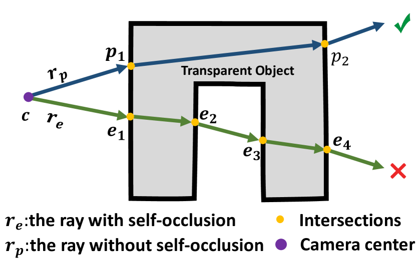
Since the objects to be reconstructed are solid, most camera rays will refract on the object surfaces exactly twice. When a ray passes through self-occluded regions, the refractions will be more complex, and the ray may refract on the surfaces more than twice. As shown in Figure 4, the light path without self-occlusion (blue line in Figure 4) has two refracted intersections with object surfaces, while the light path with self-occlusion (green line) has four refracted intersections. However, the prior works [22, 51] ignore the self-occlusion problem and assume that all the camera rays only refract exactly twice. As a result, for the rays that refract more than twice, the simulated light paths will be mistakenly approximated, thus introducing wrong supervision information into the geometry optimization.
Naive checking strategy. To tackle this problem, the key is to identify whether a ray refracts more than twice, and then exclude the ray in the optimization. A naive solution is to calculate the exact locations of the refraction intersections. As shown in Figure 4, when a ray passes through the self-occluded parts, we can leverage Snell’s law to obtain the directions of the refracted lights, and then calculate the locations of the intersections, . However, we have to extensively conduct iterative sampling and network queries to find the points sampled in the refracted lights which are in the surfaces, which significantly increases the computational costs.
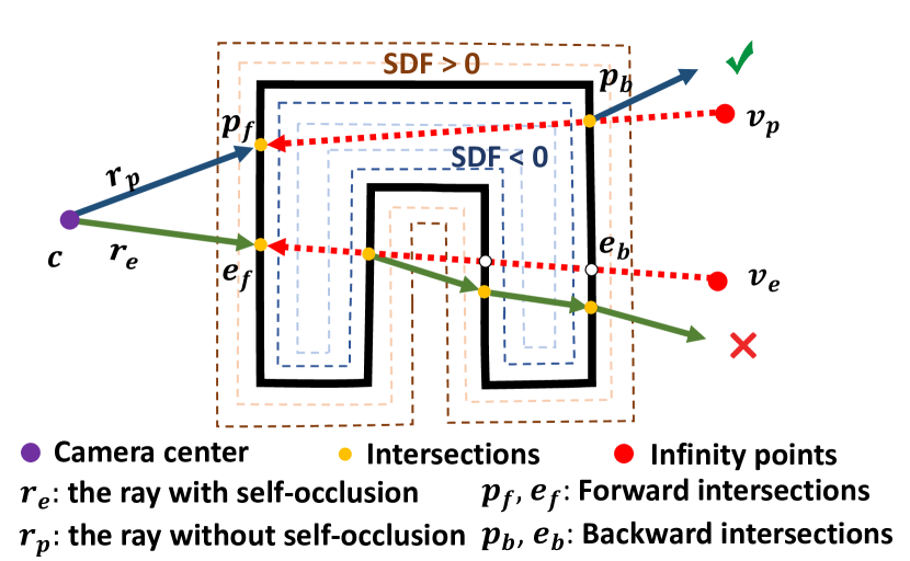
Proposed checking strategy. We, therefore, propose a simple but effective strategy to identify the rays that refract more than twice at low costs. The motivation is based on the law of reversibility, that is, If the direction of a light beam is reversed, it will follow the same path.
As shown in Figure 6, the procedure of the strategy is introduced below:
We can see the ray refracts the surfaces exactly twice, and there are no intersections on the line segment , which indicates the light path is reversible. On the other hand, for the ray , there exist two more intersections on the line segment , which indicates that the light path is not reversible with the twice refraction assumption. Moreover, thanks to the properties of SDF (negative values inside and positive values outside), we can evaluate whether there exist any points with positive SDF values between the forward and backward intersections to identify the existence of self-occlusion.
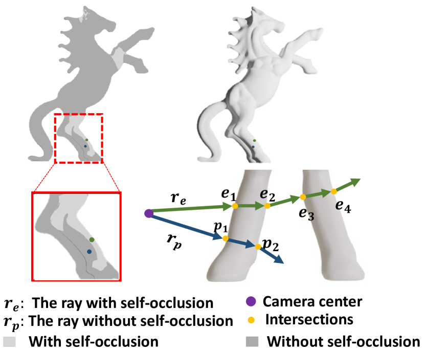
Unlike that the naive checking strategy requires accurately finding the locations of all intersections, our proposed checking strategy only needs to identify whether there exist positive SDF values in a line segment with a short length. We provide an example of the self-occlusion checking strategy applied on a real Horse object in Figure 5, and our method can accurately identify the self-occluded regions (the overlapping legs of the horse).
3.5 Loss Functions
We optimize the SDF field by sampling a batch of rays with their ray-location correspondences and object masks , where is the observed location on the background monitor, and is mask value. We sample points on the ray, and the batch size is . The loss function is defined as
| (1) |
Refraction loss. We minimize the difference between simulated background position and and its corresponding captured ground truth (see Figure 3). The refraction loss is defined as follows
| (2) |
where is the set containing ray paths that go through the object and refract on surfaces exactly twice.
With our proposed self-occlusion checking strategy, the invalid rays are excluded in the optimization, and the refraction loss gets rid of noises and makes reconstruction accurate.
| Sparsity=18 | ||||||
|---|---|---|---|---|---|---|
| Li et al. [14] | DRT[22] | Ours | ||||
| Acc. / Com. | F-score | Acc. / Com. | F-score | Acc. / Com. | F-score | |
| Pig | 2.63 / 3.01 | 0.18 | 1.87 / 1.45 | 0.35 | 0.91 / 0.88 | 0.47 |
| Dog | 3.27 / 2.87 | 0.22 | 1.51 / 1.39 | 0.36 | 0.88 / 0.78 | 0.57 |
| Mouse | 1.93 / 2.80 | 0.25 | 2.90 / 2.29 | 0.23 | 1.27 / 1.09 | 0.41 |
| Monkey | 2.59 / 3.02 | 0.20 | 2.56 / 1.60 | 0.23 | 1.02 / 0.91 | 0.41 |
| Horse | / | / | 1.95 / 1.08 | 0.51 | 0.86 / 0.79 | 0.66 |
| Tiger | / | / | 3.04 / 1.74 | 0.40 | 1.01 / 0.86 | 0.59 |
| Rabbit | / | / | 1.44 / 1.27 | 0.38 | 1.07 / 0.93 | 0.50 |
| Hand | / | / | 1.32 / 1.49 | 0.19 | 0.60 / 0.53 | 0.63 |
| Avg. | 2.60 / 2.92 | 0.21 | 2.07 / 1.53 | 0.33 | 0.95 / 0.84 | 0.53 |
Mask loss. Following the prior works [22, 51], the mask loss is also included and defined as
| (3) |
where is the sum of weights along the camera ray, is the mask of the ray, and is the binary cross entropy loss.
Eikonal loss. We add an Eikonal loss to regularize the SDF field of the sampling point on the ray to have a unit norm of gradients. The loss term is defined as
| (4) |
where is the sampled point at the ray, is the geometry function.
| Sparsity=9 | ||||||
|---|---|---|---|---|---|---|
| Li et al. [14] | DRT[22] | Ours | ||||
| Acc. / Com. | F-score | Acc. / Com. | F-score | Acc. / Com. | F-score | |
| Pig | 1.56 / 1.77 | 0.23 | 0.90 / 0.91 | 0.56 | 0.83 / 0.77 | 0.60 |
| Dog | 1.15 / 1.19 | 0.41 | 1.48 / 1.49 | 0.33 | 0.83 / 0.74 | 0.58 |
| Mouse | 1.54 / 1.63 | 0.29 | 1.32 / 1.52 | 0.36 | 0.79 / 0.72 | 0.50 |
| Monkey | 1.61 / 1.52 | 0.25 | 1.18 / 1.27 | 0.30 | 0.88 / 0.80 | 0.42 |
| Horse | / | / | 0.68 / 0.60 | 0.80 | 0.68 / 0.45 | 0.81 |
| Tiger | / | / | 1.58 / 1.23 | 0.59 | 0.85 / 0.69 | 0.71 |
| Rabbit | / | / | 0.75 / 0.77 | 0.62 | 0.67 / 0.57 | 0.73 |
| Hand | / | / | 0.88 / 0.98 | 0.32 | 0.60 / 0.53 | 0.63 |
| Avg. | 1.46 / 1.52 | 0.29 | 1.09 / 1.09 | 0.48 | 0.76 / 0.65 | 0.62 |
4 Experiments
4.1 Experimental Setup
Datasets. We conduct evaluations on the DRT [22] dataset. The dataset contains eight transparent objects. Each transparent object contains 72 views with corresponding masks, ray-pixel correspondences, and extrinsic and intrinsic camera parameters. The view resolution is or . Ground truth 3D models are also provided for the transparent models.
| Sparsity=4 | ||||||
|---|---|---|---|---|---|---|
| Li et al. [14] | DRT[22] | Ours | ||||
| Acc. / Com. | F-score | Acc. / Com. | F-score | Acc. / Com. | F-score | |
| Pig | 0.90 / 1.14 | 0.47 | 0.73 / 0.75 | 0.65 | 0.70 / 0.64 | 0.65 |
| Dog | 0.83 / 0.95 | 0.53 | 1.01 / 1.02 | 0.48 | 0.80 / 0.71 | 0.61 |
| Mouse | 1.68 / 1.69 | 0.28 | 1.16 / 1.39 | 0.40 | 0.78 / 0.70 | 0.50 |
| Monkey | 1.32 / 1.24 | 0.34 | 1.03 / 1.10 | 0.37 | 0.86 / 0.78 | 0.43 |
| Horse | / | / | 0.65 / 0.57 | 0.83 | 0.66 / 0.47 | 0.85 |
| Tiger | / | / | 1.01 / 0.87 | 0.68 | 0.73 / 0.58 | 0.79 |
| Ribbit | / | / | 0.69 / 0.72 | 0.66 | 0.61 / 0.51 | 0.79 |
| Hand | / | / | 0.84 / 1.01 | 0.43 | 0.63 / 0.49 | 0.71 |
| Avg. | 1.18 / 1.25 | 0.40 | 0.89 / 0.92 | 0.56 | 0.72 / 0.61 | 0.66 |
Implementation Details. The geometry function is modeled by an MLP, which consists of 8 hidden layers with a hidden size of 256. We use PyTorch [30] to implement our approach and use the Adam optimizer with a global learning rate for the network training. Our network architecture and initialization scheme are similar to those of prior works [46, 47]. We sample rays per batch and train our model for 300k iterations on a single NVIDIA RTX 2080Ti GPU. We extract explicit mesh from the learned SDF field via a marching cube algorithm [21].
A hierarchical sampling strategy is used to sample points along a ray in a coarse-to-fine manner for volume rendering. We first uniformly sample 64 points along the ray, and then iteratively conduct importance sampling [46] to sample more points on top of coarse probability estimation for times. The positional encoding is applied to the spatial location with 5 frequencies. The hyper-parameters used in the experiments are set as . Following the prior work [51], the IOR (index of refraction) of air is set to 1.0003 and the IOR of transparent material (glass) is set to 1.4723.
4.2 Comparisons
Baselines. We compare our method with the two state-of-the-art baselines: 1) DRT [22], the most related work to ours, which also optimizes the geometry by the ray-location correspondences but it adopts explicit mesh as surface representation. 2) A data-driven deep learning based approach Li et al. [2020] [14]. They generate a synthetic dataset of the transparent objects, and then learn geometric priors from the training data to reconstruct the objects.
| DRT[22] | Ours | |||||
|---|---|---|---|---|---|---|
| Acc | Comp | F-score | Acc | Comp | F-score | |
| Pig | 0.6566 | 0.6863 | 0.7142 | 0.5669 | 0.4689 | 0.8474 |
| Dog | 0.9072 | 0.8704 | 0.5526 | 0.7601 | 0.6274 | 0.7029 |
| Mouse | 0.8018 | 0.839 | 0.5226 | 0.7788 | 0.6811 | 0.5998 |
| Monkey | 0.945 | 0.8923 | 0.4422 | 0.8415 | 0.7467 | 0.4827 |
| Horse | 0.6636 | 0.6095 | 0.8422 | 0.6193 | 0.4099 | 0.884 |
| Tiger | 0.8191 | 0.723 | 0.7665 | 0.7099 | 0.5705 | 0.7979 |
| Rabbit | 0.5971 | 0.6202 | 0.7686 | 0.5839 | 0.4941 | 0.8324 |
| Hand | 0.4792 | 0.5856 | 0.5796 | 0.3947 | 0.3140 | 0.7740 |
| Avg. | 0.7337 | 0.7282 | 0.6485 | 0.6568 | 0.5390 | 0.7401 |
Evaluation Protocols. To evaluate the quality of reconstructed models, we calculate the metrics, accuracy, completeness, precision, recall, and F-score between the reconstructed model and the ground truth model. Our method and DRT adopt the same dataset provided by DRT, so the input images and the ground truth models adopted by ours and DRT are the same. Although Li et al. experimented with transparent objects obtained from the same source, due to different manufacturing batches, there are slight differences between the shapes, and therefore their results are compared to a different set of ground truth models. For fairness, the ground truth models of the two types are reshaped into the same scale for evaluation. We evaluate the reconstruction results with sparse views and with full dense views.
Reconstructions with sparse views. We conduct experiments under various sparsity levels. The sparse setting selects a small proportion of the camera views by consecutively sampling a view from every camera index, i.e., . The quantitative comparisons with are presented in Table 1, Table 2 and Table 3 respectively. As you can see, with sparse views, our results outperform DRT and Li et al. in terms of model completeness and accuracy. In addition to making quantitative comparisons, we render the model to visually observe the differences between our method and other methods. The qualitative comparisons are shown in Figure 7, and our method faithfully reconstructs the geometry with rich details, such as the leg of the Mouse and the eyes of the Monkey. The reconstruction results produced by [14] and [22] do not work well to reconstruct the rich geometric details and tend to over-smooth the surfaces.
Reconstruction with full views. When we use more views, e.g., full views (72 views), our reconstruction results and DRT are improved compared with reconstructions with sparse views. However, based on the quantitative results presented in Figure 8 and the qualitative results shown in Table 4, our method significantly outperforms the other methods in terms of completeness and accuracy, and the reconstructed models contain more rich details and have fewer errors. We further evaluate a self-collected real Bull and Pig object, as shown in Figure 9. Our method accurately recovers the geometry with clean and smooth surfaces, while DRT mistakenly reconstructs surfaces with noises..
| Method | Acc | Comp | Recall | Prec | F-score |
|---|---|---|---|---|---|
| W/o | 3.3086 | 1.5212 | 0.4000 | 0.5384 | 0.4597 |
| W/o | 0.7579 | 0.7019 | 0.5900 | 0.6452 | 0.6180 |
| W/o Self-occlusion | 0.6530 | 0.5440 | 0.7319 | 0.7886 | 0.7592 |
| full | 0.5669 | 0.4689 | 0.8300 | 0.8670 | 0.8474 |
4.3 Ablation study and discussions.
Ablation study. To better validate the effects of the self-occlusion checking strategy and the optimization terms, we conduct the ablation studies on the full method, method without self-occlusion checking, method without Eikonal loss term, and method without refraction loss term. The quantitative evaluation is shown in Table 5, and the qualitative evaluation is presented in Figure 10. The experiments demonstrate that plays the most important role, which encourages the SDF field to be continuous and smooth. Without the refraction loss term, although our method can still reconstruct the rough shape relying on the silhouette information, the reconstruction becomes worse with larger errors. Thanks to our proposed self-occlusion checking strategy, the quality of the self-occluded parts is improved with fewer errors, like the legs of the Pig model.
Furthermore, to better demonstrate the effectiveness of the self-occlusion checking strategy, we visualize the reconstruction error maps and the object surfaces affected by all self-occluded rays in Figure 11 (a self-occluded ray has multiple refractions on object surfaces, and thus a few rays will cause more affected surfaces), where the geometries are improved with self-occlusion check, especially on the affected regions.
Different rendering techniques. Both surface rendering [27] and volume rendering [46] are used in neural rendering-based reconstruction. Through experiments, we find that optimization using volume rendering is more robust and stable than using surface rendering. As shown in Figure 12, the reconstructed model using surface rendering is over-smoothing and lacks detailed geometries, while the reconstruction model using volume rendering achieves much better quality with rich details.
5 Conclusion and Future Work
We have presented NeTO, a novel neural rendering-based method for transparent object reconstruction, which adopts implicit signed distance function as surface representation and leverage volume rendering to enforce refraction-tracing consistency. With our proposed self-occlusion checking strategy, the reconstructed geometries of self-occluded parts are further improved. Our method significantly outperforms the state-of-the-art methods qualitatively and quantitatively by a large margin.
Although our method achieves high-quality reconstruction of transparent objects, the objects should be solid. This is because we adopt the ray-location correspondences, which assumes that most of the camera rays only refract on the object surfaces exactly twice. In the future, we would like to explore how to reconstruct hollow transparent objects, where refraction is more complex and most of the camera rays will refract on the surfaces more than twice.
6 Acknowledgments
This work is partially supported by NSFC (No.61972298).
References
- [1] Panos Achlioptas, Olga Diamanti, Ioannis Mitliagkas, and Leonidas Guibas. Learning representations and generative models for 3d point clouds. In International conference on machine learning, pages 40–49. PMLR, 2018.
- [2] Mojtaba Bemana, Karol Myszkowski, Jeppe Revall Frisvad, Hans-Peter Seidel, and Tobias Ritschel. Eikonal fields for refractive novel-view synthesis. In ACM SIGGRAPH 2022 Conference Proceedings, pages 1–9, 2022.
- [3] Guanying Chen, Kai Han, and Kwan-Yee K Wong. Tom-net: Learning transparent object matting from a single image. In Proceedings of the IEEE conference on computer vision and pattern recognition, pages 9233–9241, 2018.
- [4] Tongbo Chen, Michael Goesele, and H-P Seidel. Mesostructure from specularity. In 2006 IEEE Computer Society Conference on Computer Vision and Pattern Recognition (CVPR’06), volume 2, pages 1825–1832. IEEE, 2006.
- [5] Zhiqin Chen and Hao Zhang. Learning implicit fields for generative shape modeling. In Proceedings of the IEEE/CVF Conference on Computer Vision and Pattern Recognition, pages 5939–5948, 2019.
- [6] Christopher B Choy, Danfei Xu, JunYoung Gwak, Kevin Chen, and Silvio Savarese. 3d-r2n2: A unified approach for single and multi-view 3d object reconstruction. In European conference on computer vision, pages 628–644. Springer, 2016.
- [7] Yung-Yu Chuang, Douglas E. Zongker, Joel Hindorff, Brian Curless, David H. Salesin, and Richard Szeliski. Environment matting extensions: Towards higher accuracy and real-time capture. In Proceedings of the 27th Annual Conference on Computer Graphics and Interactive Techniques, SIGGRAPH ’00, page 121–130, USA, 2000. ACM Press/Addison-Wesley Publishing Co.
- [8] Zhaopeng Cui, Jinwei Gu, Boxin Shi, Ping Tan, and Jan Kautz. Polarimetric multi-view stereo. In Proceedings of the IEEE conference on computer vision and pattern recognition, pages 1558–1567, 2017.
- [9] Qi Duan, Jianfei Cai, and Jianmin Zheng. Compressive environment matting. The Visual Computer, 31(12):1587–1600, 2015.
- [10] Haoqiang Fan, Hao Su, and Leonidas J Guibas. A point set generation network for 3d object reconstruction from a single image. In Proceedings of the IEEE conference on computer vision and pattern recognition, pages 605–613, 2017.
- [11] Haoyu Guo, Sida Peng, Haotong Lin, Qianqian Wang, Guofeng Zhang, Hujun Bao, and Xiaowei Zhou. Neural 3d scene reconstruction with the manhattan-world assumption. In Proceedings of the IEEE/CVF Conference on Computer Vision and Pattern Recognition, pages 5511–5520, 2022.
- [12] Cong Phuoc Huynh, Antonio Robles-Kelly, and Edwin Hancock. Shape and refractive index recovery from single-view polarisation images. In 2010 IEEE Computer Society Conference on Computer Vision and Pattern Recognition, pages 1229–1236. IEEE, 2010.
- [13] Ivo Ihrke, Kiriakos N Kutulakos, Hendrik PA Lensch, Marcus Magnor, and Wolfgang Heidrich. Transparent and specular object reconstruction. In Computer graphics forum, volume 29, pages 2400–2426. Wiley Online Library, 2010.
- [14] Zhengqin Li, Yu-Ying Yeh, and Manmohan Chandraker. Through the looking glass: Neural 3d reconstruction of transparent shapes. In Proceedings of the IEEE/CVF Conference on Computer Vision and Pattern Recognition, pages 1262–1271, 2020.
- [15] Jie Liao, Yanping Fu, Qingan Yan, Fei Luo, and Chunxia Xiao. Adaptive depth estimation for pyramid multi-view stereo. Computers & Graphics, 97:268–278, 2021.
- [16] Jie Liao, Mengqiang Wei, Yanping Fu, Qingan Yan, and Chunxia Xiao. Dense multiview stereo based on image texture enhancement. Computer Animation and Virtual Worlds, 32(2):e1979, 2021.
- [17] Chen-Hsuan Lin, Wei-Chiu Ma, Antonio Torralba, and Simon Lucey. Barf: Bundle-adjusting neural radiance fields. In Proceedings of the IEEE/CVF International Conference on Computer Vision, pages 5741–5751, 2021.
- [18] Lingjie Liu, Marc Habermann, Viktor Rudnev, Kripasindhu Sarkar, Jiatao Gu, and Christian Theobalt. Neural actor: Neural free-view synthesis of human actors with pose control. ACM Trans. Graph.(ACM SIGGRAPH Asia), 2021.
- [19] Xiaoxiao Long, Cheng Lin, Lingjie Liu, Yuan Liu, Peng Wang, Christian Theobalt, Taku Komura, and Wenping Wang. Neuraludf: Learning unsigned distance fields for multi-view reconstruction of surfaces with arbitrary topologies. arXiv preprint arXiv:2211.14173, 2022.
- [20] Xiaoxiao Long, Cheng Lin, Peng Wang, Taku Komura, and Wenping Wang. Sparseneus: Fast generalizable neural surface reconstruction from sparse views. ECCV, 2022.
- [21] William E Lorensen and Harvey E Cline. Marching cubes: A high resolution 3d surface construction algorithm. ACM siggraph computer graphics, 21(4):163–169, 1987.
- [22] Jiahui Lyu, Bojian Wu, Dani Lischinski, Daniel Cohen-Or, and Hui Huang. Differentiable refraction-tracing for mesh reconstruction of transparent objects. ACM Transactions on Graphics (TOG), 39(6):1–13, 2020.
- [23] Lars Mescheder, Michael Oechsle, Michael Niemeyer, Sebastian Nowozin, and Andreas Geiger. Occupancy networks: Learning 3d reconstruction in function space. In Proceedings of the IEEE/CVF Conference on Computer Vision and Pattern Recognition, pages 4460–4470, 2019.
- [24] Ben Mildenhall, Pratul P Srinivasan, Matthew Tancik, Jonathan T Barron, Ravi Ramamoorthi, and Ren Ng. Nerf: Representing scenes as neural radiance fields for view synthesis. In European conference on computer vision, pages 405–421. Springer, 2020.
- [25] Daisuke Miyazaki and Katsushi Ikeuchi. Inverse polarization raytracing: estimating surface shapes of transparent objects. In 2005 IEEE Computer Society Conference on Computer Vision and Pattern Recognition (CVPR’05), volume 2, pages 910–917. IEEE, 2005.
- [26] Nigel JW Morris and Kiriakos N Kutulakos. Reconstructing the surface of inhomogeneous transparent scenes by scatter-trace photography. In 2007 IEEE 11th International Conference on Computer Vision, pages 1–8. IEEE, 2007.
- [27] Michael Niemeyer, Lars Mescheder, Michael Oechsle, and Andreas Geiger. Differentiable volumetric rendering: Learning implicit 3d representations without 3d supervision. In Proceedings of the IEEE/CVF Conference on Computer Vision and Pattern Recognition, pages 3504–3515, 2020.
- [28] Michael Oechsle, Songyou Peng, and Andreas Geiger. Unisurf: Unifying neural implicit surfaces and radiance fields for multi-view reconstruction. In Proceedings of the IEEE/CVF International Conference on Computer Vision, pages 5589–5599, 2021.
- [29] Jeong Joon Park, Peter Florence, Julian Straub, Richard Newcombe, and Steven Lovegrove. Deepsdf: Learning continuous signed distance functions for shape representation. In Proceedings of the IEEE/CVF Conference on Computer Vision and Pattern Recognition, pages 165–174, 2019.
- [30] Adam Paszke, Sam Gross, Soumith Chintala, Gregory Chanan, Edward Yang, Zachary DeVito, Zeming Lin, Alban Desmaison, Luca Antiga, and Adam Lerer. Automatic differentiation in pytorch. 2017.
- [31] Pieter Peers and Philip Dutré. Wavelet environment matting. In Proceedings of the 14th Eurographics Workshop on Rendering, EGRW ’03, page 157–166, Goslar, DEU, 2003. Eurographics Association.
- [32] Sida Peng, Yuanqing Zhang, Yinghao Xu, Qianqian Wang, Qing Shuai, Hujun Bao, and Xiaowei Zhou. Neural body: Implicit neural representations with structured latent codes for novel view synthesis of dynamic humans. In CVPR, 2021.
- [33] Charles Ruizhongtai Qi, Li Yi, Hao Su, and Leonidas J Guibas. Pointnet++: Deep hierarchical feature learning on point sets in a metric space. Advances in neural information processing systems, 30, 2017.
- [34] Yiming Qian, Minglun Gong, and Yee-Hong Yang. Frequency-based environment matting by compressive sensing. In Proceedings of the IEEE International Conference on Computer Vision (ICCV), December 2015.
- [35] Yiming Qian, Minglun Gong, and Yee Hong Yang. 3d reconstruction of transparent objects with position-normal consistency. In Proceedings of the IEEE Conference on Computer Vision and Pattern Recognition, pages 4369–4377, 2016.
- [36] Shunsuke Saito, Zeng Huang, Ryota Natsume, Shigeo Morishima, Angjoo Kanazawa, and Hao Li. Pifu: Pixel-aligned implicit function for high-resolution clothed human digitization. In Proceedings of the IEEE/CVF International Conference on Computer Vision, pages 2304–2314, 2019.
- [37] Shreeyak Sajjan, Matthew Moore, Mike Pan, Ganesh Nagaraja, Johnny Lee, Andy Zeng, and Shuran Song. Clear grasp: 3d shape estimation of transparent objects for manipulation. In 2020 IEEE International Conference on Robotics and Automation (ICRA), pages 3634–3642. IEEE, 2020.
- [38] Johannes Lutz Schönberger, Enliang Zheng, Marc Pollefeys, and Jan-Michael Frahm. Pixelwise view selection for unstructured multi-view stereo. In European Conference on Computer Vision (ECCV), 2016.
- [39] Qi Shan, Sameer Agarwal, and Brian Curless. Refractive height fields from single and multiple images. In 2012 IEEE Conference on Computer Vision and Pattern Recognition, pages 286–293. IEEE, 2012.
- [40] Mingqi Shao, Chongkun Xia, Dongxu Duan, and Xueqian Wang. Polarimetric inverse rendering for transparent shapes reconstruction. arXiv preprint arXiv:2208.11836, 2022.
- [41] Jonathan Stets, Zhengqin Li, Jeppe Revall Frisvad, and Manmohan Chandraker. Single-shot analysis of refractive shape using convolutional neural networks. In 2019 IEEE Winter Conference on Applications of Computer Vision (WACV), pages 995–1003. IEEE, 2019.
- [42] Jiaming Sun, Xi Chen, Qianqian Wang, Zhengqi Li, Hadar Averbuch-Elor, Xiaowei Zhou, and Noah Snavely. Neural 3d reconstruction in the wild. In ACM SIGGRAPH 2022 Conference Proceedings, pages 1–9, 2022.
- [43] Borislav Trifonov, Derek Bradley, and Wolfgang Heidrich. Tomographic reconstruction of transparent objects. In ACM SIGGRAPH 2006 Sketches, pages 55–es. 2006.
- [44] Chia-Yin Tsai, Ashok Veeraraghavan, and Aswin C Sankaranarayanan. What does a single light-ray reveal about a transparent object? In 2015 IEEE International Conference on Image Processing (ICIP), pages 606–610. IEEE, 2015.
- [45] Nanyang Wang, Yinda Zhang, Zhuwen Li, Yanwei Fu, Wei Liu, and Yu-Gang Jiang. Pixel2mesh: Generating 3d mesh models from single rgb images. In Proceedings of the European conference on computer vision (ECCV), pages 52–67, 2018.
- [46] Peng Wang, Lingjie Liu, Yuan Liu, Christian Theobalt, Taku Komura, and Wenping Wang. Neus: Learning neural implicit surfaces by volume rendering for multi-view reconstruction. arXiv preprint arXiv:2106.10689, 2021.
- [47] Yusen Wang, Zongcheng Li, Yu Jiang, Kaixuan Zhou, Tuo Cao, Yanping Fu, and Chunxia Xiao. Neuralroom: Geometry-constrained neural implicit surfaces for indoor scene reconstruction. arXiv preprint arXiv:2210.06853, 2022.
- [48] Zirui Wang, Shangzhe Wu, Weidi Xie, Min Chen, and Victor Adrian Prisacariu. Nerf–: Neural radiance fields without known camera parameters. arXiv preprint arXiv:2102.07064, 2021.
- [49] Gordon Wetzstein, David Roodnick, Wolfgang Heidrich, and Ramesh Raskar. Refractive shape from light field distortion. In 2011 International Conference on Computer Vision, pages 1180–1186. IEEE, 2011.
- [50] Ydo Wexler, Andrew Fitzgibbon, and A. Zisserman. Image-based environment matting. In Proceedings, Eurographics Workshop on Rendering, pages 289–299, January 2002. (Also presented at SIGGRAPH 2002).
- [51] Bojian Wu, Yang Zhou, Yiming Qian, Minglun Gong, and Hui Huang. Full 3d reconstruction of transparent objects. arXiv preprint arXiv:1805.03482, 2018.
- [52] Jiamin Xu, Zihan Zhu, Hujun Bao, and Wewei Xu. A hybrid mesh-neural representation for 3d transparent object reconstruction. arXiv preprint arXiv:2203.12613, 2022.
- [53] Yao Yao, Zixin Luo, Shiwei Li, Tian Fang, and Long Quan. Mvsnet: Depth inference for unstructured multi-view stereo. In Proceedings of the European Conference on Computer Vision (ECCV), pages 767–783, 2018.
- [54] Lior Yariv, Jiatao Gu, Yoni Kasten, and Yaron Lipman. Volume rendering of neural implicit surfaces. Advances in Neural Information Processing Systems, 34, 2021.
- [55] Lior Yariv, Yoni Kasten, Dror Moran, Meirav Galun, Matan Atzmon, Basri Ronen, and Yaron Lipman. Multiview neural surface reconstruction by disentangling geometry and appearance. Advances in Neural Information Processing Systems, 33:2492–2502, 2020.
- [56] Yonghao Yue, Kei Iwasaki, Bing-Yu Chen, Yoshinori Dobashi, and Tomoyuki Nishita. Poisson-based continuous surface generation for goal-based caustics. ACM Transactions on Graphics (TOG), 33(3):1–7, 2014.
- [57] Kai Zhang, Gernot Riegler, Noah Snavely, and Vladlen Koltun. Nerf++: Analyzing and improving neural radiance fields. arXiv preprint arXiv:2010.07492, 2020.
- [58] Douglas E. Zongker, Dawn M. Werner, Brian Curless, and David H. Salesin. Environment matting and compositing. In Proceedings of the 26th Annual Conference on Computer Graphics and Interactive Techniques, SIGGRAPH ’99, page 205–214, USA, 1999. ACM Press/Addison-Wesley Publishing Co.