Dynamic Event-based Optical Identification and Communication
Abstract
Optical identification is often done with spatial or temporal visual pattern recognition and localization. Temporal pattern recognition, depending on the technology, involves a trade-off between communication frequency, range and accurate tracking. We propose a solution with light-emitting beacons that improves this trade-off by exploiting fast event-based cameras and, for tracking, sparse neuromorphic optical flow computed with spiking neurons. The system is embedded in a simulated drone and evaluated in an asset monitoring use case. It is robust to relative movements and enables simultaneous communication with, and tracking of, multiple moving beacons. Finally, in a hardware lab prototype, we demonstrate for the first time beacon tracking performed simultaneously with state-of-the-art frequency communication in the kHz range.
\helveticabold1 Keywords:
Neuromorphic Computing, Event-Based Sensing, Optical Camera Communication, Optical Flow, Identification
2 Introduction
Identifying and tracking objects in a visual scene has many applications in sports analysis, swarm robotics, urban traffic, smart cities and asset monitoring. Wireless solutions have been widely used for object identification, such as RFID Jia et al. (2012) or more recently Ultra Wide Band ITU (2006), but these do not provide direct localization and require meshes of anchors and additional processing. One efficient solution is to use a camera to detect specific visual patterns attached to the objects. However, spatial pattern detection has a limited range depending on the camera’s spatial resolution. With the rise of fast cameras, temporal light patterns can be used instead, where the detection range depends only on the light intensity of emitting beacons. This technique is known as Optical Camera Communication (OCC) and has been developed primarily for communication between static objects Cahyadi et al. (2020).
In applications such as asset monitoring on a construction site, it is important to track dynamically moving objects. OCC techniques potentially enable simultaneous communication with, and tracking of, beacons. However, two challenges arise in the presence of relative movements: filtering out the noise and tracking the beacons’ positions. Increasing the temporal frequency of the transmitted signal, since noise has lower frequencies than the beacon’s signal, addresses this problem. Nevertheless, current industrial cameras do not offer a satisfying spatio-temporal resolution trade-off. Biologically-inspired event cameras, operating with temporally and spatially sparse events, achieve pixel frequencies on the order of Hz and can be combined with Spiking Neural Networks (SNNs) to build low-latency neuromorphic solutions.
In this paper, we propose to exploit the fine temporal and spatial resolution of event cameras to tackle the challenge of simultaneous OCC and tracking, where the latter is based on the optical flow computed from events by an SNN. We evaluate our approach with a simulated drone that is monitoring assets on a construction site. We further introduce a hardware prototype comprising a beacon and an event camera, which we use for demonstrating an improvement over state-of-the-art OCC range. Optical identification is commonly implemented with frame-based cameras, either by recognizing a spatial pattern in each single image – for instance for license plate recognition Du et al. (2013) – or by reading a temporal pattern from an image sequence von Arnim et al. (2007). In the latter, near-infrared blinking beacons encode a number in binary format, similarly to Morse code, to identify assets like cars or road signs. As explained before, because of the resolution/frame rate trade-off, frame-based cameras impose a hard limit on the beacon’s frequency (in the Hz order of magnitude).
Event cameras overcome this limitation by capturing individual pixel intensity changes extremely fast rather than full frames Perez-Ramirez et al. (2019). Early work combined the fine temporal and spatial resolution of an event camera with blinking LEDs at different frequencies to perform visual odometry Censi et al. (2013). Recent work also relies on smart beacons to transmit a message with the UART protocol Wang et al. (2022), delivering error-free messages of static beacons at up to 4 kbps indoors and up to 500 bps at 100 m distance outdoors with brighter beacons.
On the tracking front – to track moving beacons in our case – a widely used technique is optical flow Chen et al. (2019). Model-free techniques relying on event cameras for object detection have been implemented in Ojeda et al. (2020) and Barranco et al. (2018). To handle the temporal and spatial sparsity of an event camera, a state-of-the-art deep learning frame-based approach Teed and Deng (2020) was adapted to produce dense optical flow estimates from events Gehrig et al. (2021). However, a much simpler and more efficient solution is to compute sparse optical flow with inherently sparse biologically-inspired SNNs Orchard et al. (2013), and more recently Schnider et al. (2023).
3 Materials and Methods
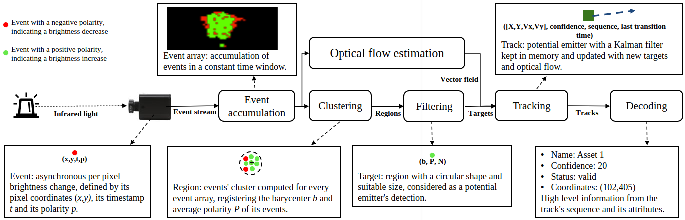
The system that we propose is composed of an emitter and a receiver. The former is a beacon emitting a temporal pattern (a bit sequence) with near infrared light (visible to cameras, but not to humans), attached to the object to be identified and tracked. The receiver component is an event-based camera connected to a computer which, in turn, executes decoding and tracking algorithms. The receiver part comprises algorithmic components for clustering and tracking for which an SNN calculates optical flow. The entire process, from low-level event-processing to high-level (bit-)sequence-decoding, is schematically depicted in Fig. 1. This figure also introduces specific terms that are used throughout the rest of this paper.
3.1 Event-Based Communication
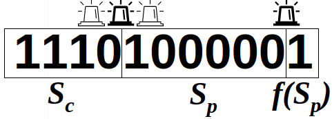
The emitter is synchronously transmitting, with a blinking pattern, a binary sequence that consists of a start code , a data payload (identification number) and a parity bit , where returns 1 if has an even number of ones, or 0 otherwise. The start code and the parity bit delimit the sequence and confirm its validity, as illustrated in Fig. 2. On the receiver side, the event camera asynchronously generates events upon pixel brightness changes, which can be caused by either a change in the beacon’s signal or visual noise in the scene. The current state of the beacon (on or off) cannot be detected by the sensor. Rather, the sensor detects when the beacon transitions between these states. The signal frequency being known, the delay between those transitions gives the number of identical bits emitted. In comparison to a similar architecture with a frame-based camera (200 Hz frame rate) as in von Arnim et al. (2007), our setup relies on an event camera and a beacon blinking in kHz frequency, allowing for a short beacon decoding time, better separation from noise and easier tracking since beacon’s motions are relatively slower.
3.2 Object Tracking
Beacons isolated by the clustering and filtering steps described in Fig. 1 are called targets. These are instant detections of the beacons. But these need be tracked in order to extract the blinking code that they produce. The tracked targets are called tracks. They hold a position (estimated or real), the history of state changes (ons and offs) and meta information like a confidence value. Tracks are categorized with types that can change over time. They can be:
-
•
new: the target cannot be associated with any existing track: create a new track
-
•
valid: the track’s state change history conforms to the communication protocol
-
•
invalid: the track’s state change history does not conform to the communication protocol (typically noise or continuous signals like solar reflections). Note that a track can change from invalid to valid if it’s confidence value rises (detailed later).
3.2.1 Clustering
Camera events are being accumulated in a time window and clustered with the Density-Based Spatial Clustering of Applications with Noise Ester et al. (1996), chosen to get rid of noisy, isolated events and to retrieve meaningful objects from the visual scene. Such clusters are filtered according to:
| (1) |
where is the number of events in the cluster, the Euclidean distance between the cluster’s barycenter and its most distant event, a shape ratio, and and the minimal/maximal emitter size in pixel. The shape ratio is a hyperparameter. In our setup, it characterizes the roundness of the cluster, since we are looking for round beacons. It can be adapted to other shapes if beacons need be flatter for example.
We reduce the remaining clusters to their barycenter, size and their polarity and call these ”targets”. The polarity of a target is given by where = for a positive polarity and for a negative one for each event .
3.2.2 Event-Based Optical Flow
Event-based optical flow is calculated by a neural network and processed by the remaining algorithmic beacon tracking pipeline. We introduce it as a given imput in the main tracking algorithm presented in the next section.
Optical flow is computed from the same camera and events that are used for decoding, and delivers a sparse vector field for visible events with velocity and direction.
We implemented an SNN architecture with Spiking Neural Units (SNUs) Woźniak et al. (2020) and extended the model with synaptic delays that we call SNU. Its state equations are:
| (2) | ||||
| (3) |
where are the weights, is a threshold, is the state of the neuron and its decay rate, is the output, is the input activation function, is the output activation function, and is the synaptic delay function. The delay function is parameterized with a delay matrix that for each neuron and synapse determines the delay at which spikes from each input will be delivered for the neuronal state calculation.
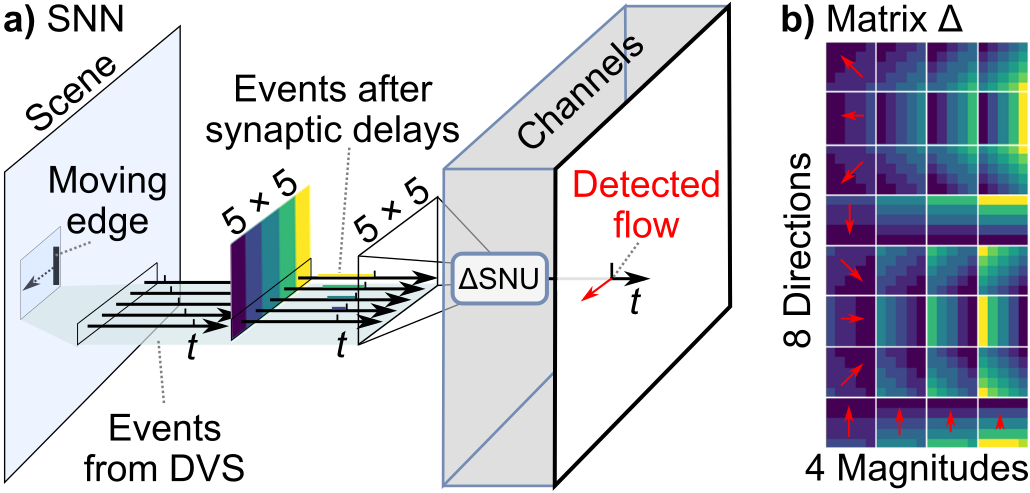
Optical flow is computed by a CNN with kernels, illustrated in Fig.3a. Each SNU is attuned to the particular direction and speed of movement through its specific synaptic delays, similarly to Orchard et al. (2013). When events matching the gradient of synaptic delays are observed, a strong synchronized stimulation of the neuron leads to neuronal firing. This results in sparse detection of optical flow. The synaptic delay kernels are visualized in Fig. 3b. We use 8 directions and 4 magnitudes, with the maximum delay period corresponding to 10 executions of the tracking algorithm. Weights are set to one and , which yielded the best tracking results.
3.2.3 Tracking
Targets are kept in memory for tracking over time and are then called tracks. A Kalman filter is attributed to each track and updated for every processed time window, as depicted in Fig. 4. A Kalman filter is needed to estimate the position of a track from the last measured one and when is not visible, either because of an occlusion, or simply because it transitioned to off. We use the estimated position’s optical flow value to draw a search window in which a target is looked for. Similarly to Chen et al. (2019), predicted tracks’ states are matched to detected targets to minimize the L1-norm between tracks and targets. Unmatched targets are registered as new tracks.
3.2.4 Identification
A matched track’s sequence is updated using the target’s mean event polarity .
-
•
If then the beacon is assumed to have undergone an on transition. We add zeros to the binary sequence where is the current timestamp, is the stored last transition timestamp and is the beacon blinking frequency and set .
-
•
If then the beacon is assumed to have undergone a transition to the off state. Likewise, we add ones to the binary sequence.
-
•
Otherwise, the paired beacon most likely has not undergone a transition but just moved.
Similarly to von Arnim et al. (2007), a confidence value is incremented or decremented to classify tracks as new, valid or invalid, as illustrated in Alg.1. Indeed, noise can pass clustering filters but will soon be invalidated as its confidence will never rise. To correct for errors (for instance due to occlusions), the confidence increments are larger than decrements. When a track’s sequence is long enough to be decoded, it is declared valid if it complies to the protocol and maintains the same payload (if this track was previously correctly recognized). New tracks have an initial confidence value confidence. These values have been experimentally set to optimize for our protocol and an expected mean occlusion duration. They can be adapted for expected longer off states or longer occlusions. Though, the level of track robustness to occlusion and its ”stickyness” have to be balanced. Indeed, higher confidence thresholds lead to a longer detection time and also a longer time to become invalid. A clean up of tracks having been invalid for too long is necessary in all cases to save memory. This is done with a simple threshold (confidence) or a time out (delay) mechanism. These hyperparameters can also be experimentally tuned.
4 Results
4.1 Static Identification
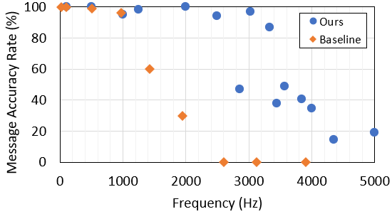
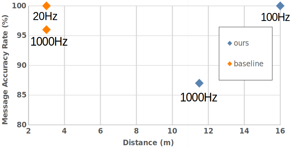
Our hardware beacon has four infrared LEDs (850 nm) and an ESP32 micro-controller to set the payload and the blinking frequency. To receive the signal, we used a DVXplorer Mini camera, with a resolution of 640480 and a 3.6 mm focal length lens. In a static indoor setup, the hardware event camera enables us to achieve high data transmission frequencies, plotted in Fig. 5. The metric is the Message Accuracy Rate (MAR): the percentage of correct 11-bit sequences decoded from the beacon’s signal during a recording. The MAR stays over 94 % up to 2.5 kHz, then decreases quickly, due to the temporal resolution of the camera. Using a 16 mm focal length lens we could identify the beacon at a distance of 11.5 m indoors, with 87 % MAR and a frequency of 1 kHz and obtained 100 % MAR at 100 Hz at 16 m – see Fig 6.
A special note has to be made regarding the range. Results are given here for information purpose. The range cannot really be considered a benchmarking parameter because it depends essentially on the beacon signal power and on the camera lens. To improve the detection and MAR at a longer range, adding LEDs to the beacon, or choosing a zooming lens, are good solutions. So this is basically an implementation choice.
4.2 Dynamic Identification
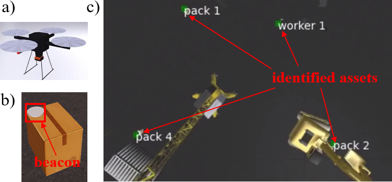
To evaluate our identification approach in a dynamic setup, where tracking is required, a simulated use case was developed in the Neurorobotics Platform Falotico et al. (2017). A Hector drone model, with an on-board event camera plugin Kaiser et al. (2016), flies over a construction site with assets (packages and workers) to be identified and tracked. These are equipped with blinking beacons. The drone follows a predefined trajectory and the scene is captured from a bird’s eye view – see Fig. 7. A frame-based camera with the same view is used for visualization. Noise is simulated with beacons of different sizes blinking randomly. For varying drone trajectories, assets were correctly identified at up to 28 m, with drone speeds up to 10 m/s (linear) and 0.5 radian/s (self rotational). Movements were fast, relative to the limited 50 Hz beacon frequency imposed by the simulator. A higher MAR was obtained with a Kalman filter integrating optical flow (3.2.3) than without it – see Tab. 1. MAR and Bit Accuracy Rate (BAR) are correlated in simulation because they drop together only upon occlusion. Finally, we conducted hardware experiments where a beacon was moved at 2 m/s reaching a 94 % BAR at 5m and a 87 % BAR at 16m. This shows that our system enables accurate identification and data transmission even with moving beacons, which, to our knowledge, is beyond the state-of-the-art.
5 Discussion
| Setup | Rate | Range | MAR | BAR |
|---|---|---|---|---|
| Simulation with optical flow | 50 Hz | 28 m | 74 % | 75 % |
| Simulation without optical flow | 50 Hz | 28 m | 71 % | 72 % |
| Hardware | 2000 Hz | 5 m | 65 % | 94 % |
| Hardware | 2000 Hz | 16 m | 27 % | 87 % |
We propose a novel approach for identification that combines the benefits of event-based fast optical communication and signal tracking with spiking optical flow. The approach was validated in a simulation of drone-based asset monitoring on a construction site. A hardware prototype setup reached state-of-the-art optical communication speed and range. We propose the first – to the best of our knowledge – system to identify fast moving, variable beacons with an event camera, thanks to our original tracking approach. Event-based camera, thanks to their extremely low pixel latency, do outperform OCC based on frame grabbers by orders of magnitude. This enables beacon signal frequencies up to 5 kHz, which in turn, enables for their more robust tracking, since their relative movement is slow between two LED state transitions. Nevertheless, tracking is still necessary for beacons moving fast and that is where this work goes beyond Wang et al. (2022), which assumes null or negligible beacon movement.
Further research includes the port of optical flow computation to neuromorphic hardware and the full port of the system onto a real drone, for real world assessment. Although the current work is mainly algorithmic with optical flow realized in a spiking neural network, this paper proves that it is very efficient. Now, as this mixes two computing paradigms (algorithmics and spiking neural networks), it will entail having two computing devices on board a real drone. Another research direction of ours is thus to investigate a full spiking implementation, so as to carry only neuromorphic hardware on board.
Conflict of Interest Statement
The authors declare that the research was conducted in the absence of any commercial or financial relationships that could be construed as a potential conflict of interest.
Author Contributions
AvA and JL have carried out the research and implementation of the algorithmic and integration work. NEB and SW have investigated and implemented the optical flow neural network, under supervision of AP. AP and AvA have supervised the work for respectively IBM and fortiss and have approved the content of this publication.
Acknowledgements
The research was carried out within the Munich Center for AI (C4AI), a joint entity from fortiss and IBM. We thank the C4AI project managers for their constructive help. The research at fortiss was supported by the HBP Neurorobotics Platform funded through the European Union’s Horizon 2020 Framework Program for Research and Innovation under the Specific Grant Agreements No. 945539 (Human Brain Project SGA3).
References
- Barranco et al. (2018) Barranco, F., Fermuller, C., and Ros, E. (2018). Real-time clustering and multi-target tracking using event-based sensors. In 2018 IEEE/RSJ International Conference on Intelligent Robots and Systems (IROS). 5764–5769. 10.1109/IROS.2018.8593380
- Cahyadi et al. (2020) Cahyadi, W. A., Chung, Y. H., Ghassemlooy, Z., and Hassan, N. B. (2020). Optical camera communications: Principles, modulations, potential and challenges. Electronics 9. 10.3390/electronics9091339
- Censi et al. (2013) Censi, A., Strubel, J., Brandli, C., Delbruck, T., and Scaramuzza, D. (2013). Low-latency localization by active led markers tracking using a dynamic vision sensor. In 2013 IEEE/RSJ International Conference on Intelligent Robots and Systems. 891–898. 10.1109/IROS.2013.6696456
- Chen et al. (2019) Chen, Y., Zhao, D., and Li, H. (2019). Deep kalman filter with optical flow for multiple object tracking. In 2019 IEEE International Conference on Systems, Man and Cybernetics (SMC). 3036–3041. 10.1109/SMC.2019.8914078
- Du et al. (2013) Du, S., Ibrahim, M., Shehata, M., and Badawy, W. (2013). Automatic license plate recognition (alpr): A state-of-the-art review. IEEE Transactions on Circuits and Systems for Video Technology 23, 311–325. 10.1109/TCSVT.2012.2203741
- Ester et al. (1996) Ester, M., Kriegel, H.-P., Sander, J., and Xu, X. (1996). A density-based algorithm for discovering clusters in large spatial databases with noise. In Knowledge Discovery and Data Mining
- Falotico et al. (2017) Falotico, E., Vannucci, L., Ambrosano, A., Albanese, U., Ulbrich, S., Vasquez Tieck, J. C., et al. (2017). Connecting artificial brains to robots in a comprehensive simulation framework: The neurorobotics platform. Frontiers in Neurorobotics 11. 10.3389/fnbot.2017.00002
- Gehrig et al. (2021) Gehrig, M., Millhäusler, M., Gehrig, D., and Scaramuzza, D. (2021). E-RAFT: Dense Optical Flow from Event Cameras. arXiv:2108.10552 [cs] ArXiv: 2108.10552
- ITU (2006) ITU (2006). Characteristics of ultra-wideband technology
- Jia et al. (2012) Jia, X., Feng, Q., Fan, T., and Lei, Q. (2012). Rfid technology and its applications in internet of things (iot). In 2012 2nd International Conference on Consumer Electronics, Communications and Networks (CECNet). 1282–1285. 10.1109/CECNet.2012.6201508
- Kaiser et al. (2016) Kaiser, J., Tieck, J. C. V., Hubschneider, C., Wolf, P., Weber, M., Hoff, M., et al. (2016). Towards a framework for end-to-end control of a simulated vehicle with spiking neural networks. In 2016 IEEE International Conference on Simulation, Modeling, and Programming for Autonomous Robots (SIMPAR). 127–134. 10.1109/SIMPAR.2016.7862386
- Ojeda et al. (2020) Ojeda, F. C., Bisulco, A., Kepple, D., Isler, V., and Lee, D. D. (2020). On-device event filtering with binary neural networks for pedestrian detection using neuromorphic vision sensors. In 2020 IEEE International Conference on Image Processing (ICIP). 3084–3088. 10.1109/ICIP40778.2020.9191148
- Orchard et al. (2013) Orchard, G., Benosman, R., Etienne-Cummings, R., and Thakor, N. V. (2013). A spiking neural network architecture for visual motion estimation. In 2013 IEEE Biomedical Circuits and Systems Conference (BioCAS) (Rotterdam, Netherlands: IEEE), 298–301. 10.1109/BioCAS.2013.6679698
- Perez-Ramirez et al. (2019) Perez-Ramirez, J., Roberts, R. D., Navik, A. P., Muralidharan, N., and Moustafa, H. (2019). Optical wireless camera communications using neuromorphic vision sensors. In 2019 IEEE International Conference on Communications Workshops (ICC Workshops). 1–6. 10.1109/ICCW.2019.8756795
- Schnider et al. (2023) Schnider, Y., Woźniak, S., Gehrig, M., Lecomte, J., von Arnim, A., Benini, L., et al. (2023). Neuromorphic optical flow and real-time implementation with event cameras. IEEE Conference on Computer Vision and Pattern Recognition Workshops (CVPRW), Vancouver, 2023. c IEEE
- Teed and Deng (2020) Teed, Z. and Deng, J. (2020). RAFT: Recurrent All-Pairs Field Transforms for Optical Flow ArXiv:2003.12039 [cs]
- von Arnim et al. (2007) von Arnim, A., Perrollaz, M., Bertrand, A., and Ehrlich, J. (2007). Vehicle Identification Using Near Infrared Vision and Applications to Cooperative Perception
- Wang et al. (2022) Wang, Z., Ng, Y., Henderson, J., and Mahony, R. (2022). Smart visual beacons with asynchronous optical communications using event cameras 10.48550/ARXIV.2208.01710
- Woźniak et al. (2020) Woźniak, S., Pantazi, A., Bohnstingl, T., and Eleftheriou, E. (2020). Deep learning incorporating biologically inspired neural dynamics and in-memory computing. Nature Machine Intelligence 2, 325–336. 10.1038/s42256-020-0187-0