Enhanced beam shifts mediated by Bound States in Continuum
Abstract
The interaction of light beams with resonant structures has led to the development of various optical platforms for sensing, particle manipulation, and strong light-matter interaction. In the current study, we investigate the manifestations of the bound states in continuum (BIC) on the in plane and out of plane shifts (referred to as Goos-Hänchen (GH) and Imbert-Fedorov (IF) shifts, respectively) of a finite beam with specific polarization incident at an arbitrary angle. Based on the angular spectrum decomposition, we develop a generic formalism for understanding the interaction of the finite beam with an arbitrary stratified medium with isotropic and homogeneous components. it is applied to the case of a Gaussian beam with and circularly polarized light incident on a symmetric structure containing two polar dielectric layers separated by a spacer layer. For -polarized plane wave incidence one of the coupled Berreman modes of the structure was recently shown to evolve to the bound state with infinite localization and diverging quality factor coexisting with the other mode with large radiation leakage (Remesh et al. Optics Communications, 498:127223, 2021). A small deviation from the ideal BIC resonance still offers resonances with very high quality factors and these are exploited in this study to report giant GH shifts. A notable enhancement in the IF shift for circularly polarized light is also shown. Moreover, the reflected beam is shown to undergo distortion leading to a satellite spot. The origin of such a splitting of the reflected beam is traced to a destructive interference due to the left and right halves of the corresponding spectra.
Keywords: bound states in continuum, epsilon near zero, spin-orbit interaction, GH and IF shifts
1 Introduction
It is now well understood that in contrast to the predictions of geometrical optics, a finite beam can exhibit both spatial and angular shifts under reflection and transmission [1]. The in-plane and out of plane spatial shifts, customarily known as the Goos–Hänchen (GH) and Imbert–Fedorov (IF) shifts, have been studied in great detail, not only for their fundamental interest, but also for their numerous potential applications. While GH shift is sensitive to the pole of the reflection/transmission coefficients, it may lead to different amount of shifts for -(TM or Transverse Magnetic) and -(TE or Transverse Electric) polarized plane waves. In contrast, the IF shift owes its origin to the angular momentum carried by the incident beam (for example, for circularly polarized plane waves) leading to the so-called spin-Hall effect of light [2, 3, 4]. In case if the light is structured (as in case of evanescent waves or beams), it can lead to many other manifestations of spin-orbit interaction (SOI) like transverse spin, elusive Belinfante momentum, spin locking etc (see [5], along with [1, 2] and the references therein). Recently, the Optical Spin Hall effect (spin-orbit locking) has been experimentally demonstrated using a -negative/-negative [Chen2017] and a hyperbolic waveguide [Hong2021]. Earlier studies on the spatial shifts were carried out with dielectric or metal-dielectric layered media, where such structures facilitated the excitation of guided or surface modes with very high local fields and strong confinement. As a consequence the otherwise tiny shifts (order of wavelength or less) could be enhanced significantly exploiting the large dispersion around these resonances [6, 7, 8]. . Recent studies focus on lower dimensional systems like metasurfaces or 2D materials like doped graphene [3, 9, 10]. Pump controlled atomic medium has been shown to lead to tunable GH shifts [11]. There have been numerous applications for new sensing technology, precision measurements [12, 13, 14, 15], optical switching [16] to name a few. Another interesting direction has opened up exploiting the weak value amplification techniques to amplify the weak shifts [17, 18, 19, 20].
In the context of extra narrow resonances, the bound states in continuum (BIC) have lot of promises, since they offer infinite confinement with diverging quality factors. In view of the exotic fundamental physics and potential for novel applications they have been studied extensively resulting in vast literature [21, 22]. Though originally proposed for a quantum mechanical model [23], studies on BIC now extend to various different branches of physics with typical classifications like symmetry protected, accidental, Friedrich-Wintgen etc. [21, 24, 25, 26, 27]. The exotic properties of BICs such as the high Q-factor and field localization have been exploited for different ends, such as allowing them to act as efficient lasing cavities [28, 29]. In addition, the topological nature of BICs found in photonic crystals allows them to emit light carrying orbital angular momentum [30, 31]. They can also be used in sensing, using the shift in the resonances with the change in the background refractive index. The strong dependence of the resonance position on the refractive index of the background medium of a BIC supporting structure can be used as a non-destructive sensing technique to measure the refractive index in biological systems [32]. Very recently BIC has been exploited to show large enhancements in the in-plane GH shifts and its possible application for temperature and refractive index sensing [33, 34]. However, both these studies use Artmann formula [35] for calculating the GH shifts. It is now well understood that the Artmann formula hinges on the stationary phase approximation, which does not hold for abrupt variation of phase near the extra high-Q resonances [36, 37]. It is thus necessary to adopt a more rigorous theory based on angular spectrum decomposition to calculate the shifts for BIC.
One of the simplest ways to implement a BIC in photonic systems is to make use of the Fabry-Perot type BIC, where light is trapped between two resonant structures, which act as perfect reflectors [38, 39, 40, 41]. In this context metallic and polar dielectric films are attractive since at specified frequencies they can exhibit epsilon near zero (ENZ) behavior [39, 42, 43]. Polar dielectrics materials are characterized by its longitudinal optical (LO) and transverse optical (TO) phonon frequencies and respectively. The real part of the dielectric permittivity of these materials tend to zero near . Very thin polar dielectric films have an additional advantage that they support the Berreman modes [43, 44, 45]. These modes can be interpreted as virtual modes that emerge near the LO phonon frequency inside the light-cone for thin polar dielectric films. The absorption peak observed at the LO phonon frequency for thin films [44] can be attributed to the excitation of these modes [43]. Being inside the lightcone, these leaky modes can be excited using propagating waves. The strong field confinement upon excitation of these modes has lead to several interesting nonlinear optical applications, for example, second-harmonic generation [45, 46]. In a recent paper a symmetric structure with two polar dielectric films separated by a air gap supporting coupled Berreman modes was studied. The Berreman modes in each film can couple to form a symmetric and antisymmetric mode, one of which can have null-width for suitable set of parameters, implying the transition to BIC [38]. It was shown that the ENZ condition was essential for the BIC, since as mentioned above the polar dielectric layers then behave as ideal reflectors (in absence of losses).
It is quite suggestive that the high quality factor, field localization and dispersion of BICs would make them an ideal candidate for enhancing the beamshifts. Even the quasi BICs (occurring slightly away from the ideal BIC resonance) offer enhanced quality factors. In this paper, we study the beam profiles and shifts of a Gaussian beam incident on the structure supporting coupled Berreman modes described above. While the previous study determined the effects of a -polarized plane wave, our current formalism is suited to a generic beam at arbitrary angle of incidence. In developing the formalism and the code we followed [1] adding few important improvements. The formalism is applicable to general beams such as vector beams or OAM-carrying beams, though the results for only linearly or circularly polarized Gaussian beams are presented in this paper. We show an enhancement of the shift due to the strong field enhancement caused by quasi-BIC. We report a giant enhancement in the GH shift for incident -polarized beam, while there is a discernible enhancement in the IF shift for circularly polarized light. We also report a distinct deformation of the reflected beam resulting in the formation of a satellite spot which is explained by means of an intriguing destructive interference.
The organisation of the paper is as follows. After a summary of the general formulation of the problem, we describe our system supporting the coupled Berreman modes in Section 2. In Section 3, we discuss the numerical results as regards the beam profiles both in the momentum and space domains for both reflected and transmitted beams. The beamshifts are then calculated from the spatial profiles of the reflected and transmitted beams. Finally we summarize the main results and future outlook in Conclusions.
2 Formulation of the Problem
In this Section we outline the procedure for a generic code for beam shape and associated shifts of the reflected and transmitted beams for a general multilayered medium for incidence of a vector beam at an arbitrary angle of incidence. Each constituent of the multilayered medium is assumed to be isotropic and homogeneous. The code can handle any beam ranging from a simple Gaussian to more complicated LG, or radially / azimuthally polarized vector beams. Our procedure is based on the approach developed by Bliokh et al. [1] albeit for a single interface, except for two notable improvements. The first one concerns the strong paraxial approximation allowing for linear deviations for the wave vector deflections from the central wave vector in the beam frame (see eq. (3.9) in [1]). Note that this approximation renders the theory not applicable to normal incidence, since for normal incidence lowest order contributions come from quadratic and higher order terms. Though we deal with paraxial beams using a Jones formalism we do not use any approximations for the polar and azimuthal angles for any off-axis vector component. The second improvement concerns the use of exact values of complex amplitude reflection and transmission coefficients for the structure as opposed to the Taylor series expansion of these quantities retaining only the linear terms as in [1]. Evidently, both these improvements make it impossible to have closed form expressions for the beam shifts, which is one of the major achievements of reference [1]. Another limitation of the current approach stems from the Jones formalism with no reference to the longitudinal field components. One can not thus study transverse spin effects which draw their origin from the longitudinal component in tight focusing. We have tested our code for both the cases of normal and oblique incidence and reproduced the results of references [47, 48] and [1], respectively. Note that we are empowered to generate the output beam profile which was missing in [47, 48] to explicitly confirm the predictions of their study. We now list out the major steps retaining the notations of [1] wherever possible and later apply the method to study our system supporting BIC. Here we use only incident Gaussian beam, though the formalism can yield results for other more general beams.
Consider a Gaussian beam having the normalized spectrum given by [1, 49]
| (1) |
be incident on the stratified medium. In eq. 1, is the beam width and the second parenthesis represents the state of polarization of the beam with subscripts labelling the mutually orthogonal and polarized components. Let the central wave vector of the beam be incident at an angle (with corresponding reflection and transmission angles and , respectively). For any off-axis wavevector component in the beam frame, the local polar and azimuthal angles, for example, for the incident beam are given by [49]
| (2) |
| (3) |
where . Such local angles and are obtained also for reflected and transmitted beams and facilitate the rotational transformation from the beam frame to the basis of and modes. In order to calculate the output spectra of the reflected and transmitted beams one would require the corresponding reflection and transmission coefficients for each spatial harmonic for both and polarizations. These quantities (, respectively) are calculated using the characteristic matrix approach [50] for each of these harmonics. Thus the output spectra are given by [1]
| (4) |
where
| (5) | |||
| (6) |
with , denoting the relevant quantities for incident, reflected and transmitted fields. are rotation matrices about axes in the laboratory frame. in eq.4 is obtained by setting in eq.5. As mentioned earlier Bliokh et al. used a linear approximation for calculating the local angles and , and to approximate the reflection and transmission coefficients for off-central components, which is applicable only in the strong paraxial regime. We calculate them exactly using eq. 2 and eq. 3 allowing us to employ beams with larger transverse spread. As mentioned above the matrix contains the information for reflection and transmission properties of the structure. Feeding the information for Fresnel coefficients and rotation matrices for each wavevector (on or off-central) of the incident Gaussian beam, the reflected and transmitted spectra are calculated. The inverse Fourier transform of the spectra given by eq. 4 then yields the corresponding beam spatial profiles. In order to investigate the spatial in-plane (Goos-Hänchen) and out-of-plane (Imbert-Fedorov) shifts, we calculate the centre of gravity of the reflected and transmitted beams using [51]
| (7) | |||
| (8) |
where refer to the reflected and transmitted beams, respectively.
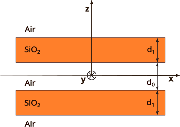
We now apply the above formalism to the symmetric multilayered medium in Fig. 1. Recall that a single SiO2 film on a gold substrate was studied [43] for probing the leaky Berreman modes [44]. One of the coupled Berreman modes of the structure shown in Fig. 1 was shown to evolve to the BIC under continuous tuning of the system parameters [38]. The dielectric function of SiO2 was taken to be [43],
| (9) |
Typical parameters for polar SiO2 are , rad/s, rad/s, rad/s. However, in order to look for BIC, losses were ignored by setting [38]. It was shown earlier that Epsilon-near-zero (ENZ) behavior at is essential for the occurrence of BIC, since under ENZ condition the polar dielectric layers act as perfect mirrors. The angle at which the BIC occurs can be found from the phase-matching condition, which is given by,
| (10) |
where is the wavevector of light in vacuum, is the thickness of the spacer layer of the structure and is an integer. The angle of incidence of the central wavevector of the incident Gaussian beam was chosen near this BIC angle, which would hence excite the quasi-BIC resonances with finite widths in the structure.
3 Results and Discussion
In this Section we present the numerical results. We proceed as follows. We recall some of the relevant results from the earlier study [38] pertaining to the reflection and transmission coefficients for -polarized plane wave incidence just to focus on the particular quasi BIC at a given angle of incidence. Recall that as predicted by eq. 10, there can be higher order BICs discussed in detail in [38]. An angle close to this is then chosen to be the angle of incidence of the central wave vector of the -polarized Gaussian beam. We have also looked at circularly polarized Gaussian beams to infer on the IF shifts. Henceforth, the formalism developed in the previous section is applied to obtain the spectra, their originals and the corresponding in-plane and out of plane shifts.
We recall the parameters used for the numerical studies. The relevant parameters for eq. 9 are , rad/s, rad/s, rad/s. The thickness of the SiO2 and air layers were taken to be m and m. The angle of incidence of the beam was chosen to be , which is close to the angle at which BIC occurs (one of the resonances of eq. 10). Recall that BIC requires the ENZ condition of .
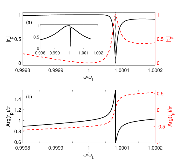
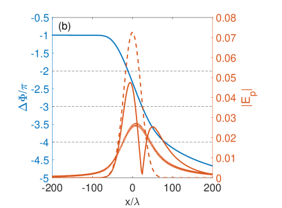
The results for -polarized plane wave incidence are shown in Fig. 2, where we have plotted the absolute values of the amplitude reflection and transmission coefficients along with their phases as functions of frequency at a fixed incidence angle of . Since we are working at angles slightly away from the BIC, the quasi-BICs are excited at a frequency shifted from . One can notice the sharp dip (peak) in the reflection (transmission) coefficients in Fig. 2 at . The inset in Fig. 2a shows the reflection coefficient over larger frequency domain in order to appreciate the ultra-narrow BIC dip. It is important to note the phase jump in reflection at the BIC dip, which, as will be shown below, plays an important role in determining the reflected beam profile.
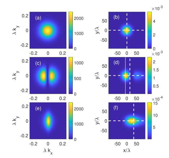
In the context of the polarized Gaussian beam incidence we choose the frequency and angle of incidence corresponding to the quasi-BIC dip location in 2(a), namely, and , so that a spatial harmonic (plane wave) corresponding to the central wavevector of the beam would excite the quasi-BIC. The beam waist of the incident Gaussian beam was chosen to be , where is the wavelength of the light used.
The intensity spectra of the incident, reflected and transmitted beams (obtained using eq. 1 and eq. 4 are shown in Figs. 3a,c,e. The corresponding spatial intensity distributions (from inverse Fourier transforms) are shown in the right panels. Clearly, the two lobes (hereafter referred to as left and right lobe) in Fig. 3c owe their origin to the sharp BIC dip in reflection for the central component with analogous dips for nearby spatial harmonics wherever the angle of incidence is near the quasi-BIC angle. Note that corresponds to the central wavevector of the obliquely incident Gaussian beam in the beam frame. The signature of BIC shows up as a bent vertical strip in the phase plot in the () plane (not shown). One can also relate the origin of the dark strip to the phase change as one moves from the left to the right lobe. The inverse Fourier transforms of the momentum space spectra yield the corresponding spatial intensity distributions (see Figs.3b,d,e). Even though the incident beam is -polarized, the reflected and transmitted light spatial intensities have contributions from -polarization also because of mixing for off-central wave vector components (albeit about five orders of magnitude smaller than the former). Having obtained the reflected and transmitted spatial profiles, the GH and IF shifts of the center of gravity (CG) for relevant polarizations of the incident beam can now be calculated using eq. 7. Due to the split spectrum of the reflected light, the corresponding spatial profile exhibits distortion leading to a faint additional spot as shown in Fig. 3d. We refer to the bright and lighter spots in Fig. 3d as the main and satellite spots. Somewhat reminiscent emergence of satellite spot has been reported in reflection of higher order Gaussian beams, albeit due to tight focusing [8, 37]. The origin of these spots can be traced to interesting destructive interference effects discussed below. Finally in order to assess the shift of the reflected beam, we calculate the same retaining both the spots and also by suppressing the satellite spot by setting the field amplitude to be zero for (location of the intensity minimum of the beam) in the reflected beam profile in Fig. 3d. The white dashed cross-hair marks the CGs of the overall intensity distributions, while the intersection of the dashed and dotted line mark the CG with suppressed satellite spot.
We now elaborate on the emergence of satellite spots in Fig.3d. The reflected beam can be thought of as superposition of two spectra corresponding to the left and right lobes in momentum space (Fig.3d). We look at the inverse Fourier transform (spatial image) of these -space lobes. Recall that the reflected spectra has contributions from both and -polarizations because of the aforementioned mixing of off-central wave vector components. However, since -polarization plays the dominant role in BIC, we retain only the -component of the electric field . This is justified because , as pointed out before. The spatial intensity distribution corresponding to the left lobe (see Fig.3c), obtained by inverse Fourier transforming the spectra after setting the field amplitude to zero for is plotted in Fig.4a. The spatial intensity distribution of the left and right lobes happens to be almost identical. However, corresponding phases play a very important role. In order to probe the underlying interference phenomena, we take a cross-section of this spatial image at and study the trend of amplitude and phase. The results are shown in Fig.4b. As mentioned earlier, the amplitudes of the left and right lobes more or less match whereas the phase difference between the two shows a monotonically decreasing behavior. At the point where reaches an odd multiple of (here, ) one can see a clear signature of destructive interference, causing the dip, resulting in the main and satellite spots, the left main being the stronger one.
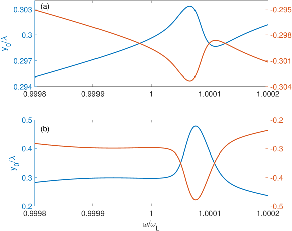
In what follows we present the explicit results for the enhancement of beamshifts due to the quasi-BIC. For studying Goos-Hänchen shift, we consider -polarized incident light. Analogous calculations can be carried out for -polarized light also, but the coupled Berreman modes near the ENZ condition, whose mutual interactions leads to the BIC cannot be efficiently excited for -polarized incidence [38]. In Fig. 5a, the solid (dashed) line gives the shift for the overall (main) reflected spot as a function of normalized frequency, which clearly shows the enhanced shift upon excitation of the quasi-BIC. Note that assessing the GH shift of the distorted reflected beam (overall spatial distribution retainng both main and the satellite spots) can be quite misleading because of the loss of its Gaussian character of the reflected beam. In contrast, the shift retaining only the main spot (suppressing the satellite in Fig.3d), in our opinion, gives a better estimate of the acceptable GH shift. Importantly these two approaches yield results with opposite signs. Needless to mention that the Imbert-Fedorov shift is negligible for -polarization as expected. The corresponding shift for the transmitted beam is shown in Fig. 5b. Clearly the GH-shifts for both reflected and transmitted beams receive giant enhancements thanks to the large quality factor of the quasi-BIC. Changing the structural parameters of our system can change the angle of incidence or quasi-BIC frequency. The different possible parameters in the available parameter space might lead to different beam shifts, different relative intensities of the satellite spots, etc. However, the general features shown in our system (enhancement of shifts, distortion of reflected beam and splitting into unequal spots, etc) are seen throughout the parameter space we explored.
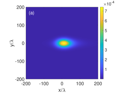
Finally, we look at the out-of-plane IF shift for incident LCP light. The results for spectra and the corresponding spatial profiles for the transmitted beam are shown in Fig. 6. Clearly the transmitted beam retains the Gaussian character. The reciprocal behavior of the and domain is clearly seen from a comparison of Figs. 6a and b, since the narrower the spectra in direction, broader the spatial profile in the corresponding direction. As can be seen, the IF shift of the transmitted light is also associated with the in-plane GH shift. The similar but smaller enhancement of Imbert-Fedorov shift is observed for circularly-polarized light in Fig. 7. The small shift is probably related to the paraxially incident beam that we have used. A highly focused non-paraxial beam has been shown to show strong SOI effects: for example, beams tightly focused by high-numerical-aperture lenses [4, 52, 53] or scattered by small particles [2, 54]. Moreover our system supports BIC only for - polarized light, since -polarized light can not excite the Berreman modes. Since the circularly (or elliptically) polarized light is a prerequisite for IF shift it does not experience the giant shift as experienced by the lateral GH shift. Obviously, the magnitude of shifts is the same in LCP and RCP beams but in opposite directions.
4 Conclusions
In conclusion, we have studied a symmetric layered medium comprising of two polar dielectric Si films supporting bound states in continuum mediated by the coupled Berreman modes. We developed a general code for reflection and transmission of a Gaussian or vector beam through a stratified medium overcoming some of the strong paraxial approximations. The code is then applied to a Gaussian beam incident on the structure under study. We have shown theoretically that the extra-large quality factor and the resulting field enhancement associated with the quasi-BIC in the structure can lead to giant enhancements in the in-plane Goos-Hänchen shifts which could be comparable to the beam spot size. Moreover, quasi-BIC is shown to distort the reflected beam to the extent of formation of a satellite spot. We systematically analyze the formation of the satellite spot as a consequence of an interesting destructive interference between the split lobes in the spectral profile of the reflected beam. We estimated the beam shifts for both linear and circular polarization of the incident Gaussian beam. Work is underway to consider richer structured beams (eg., LG or radially or azimuthally polarized vector beams) carrying angular momenta and will be reported elsewhere. Needless to mention that such studies are extremely important not only for fundamental understanding but also for novel nearfield applications for micro manipulation of particles.
References
References
- [1] K Y Bliokh and A Aiello. Goos–hänchen and imbert–fedorov beam shifts: an overview. Journal of Optics, 15(1):014001, jan 2013.
- [2] Konstantin Bliokh, Francisco Rodríguez-Fortuño, Franco Nori, and Anatoly Zayats. Spin-orbit interactions of light. Nature Photonics, 9, 05 2015.
- [3] Xiaobo Yin, Ziliang Ye, Junsuk Rho, Yuan Wang, and Xiang Zhang. Photonic spin hall effect at metasurfaces. Science, 339(6126):1405–1407, 2013.
- [4] Ram Nandan Kumar, Yatish, Subhasish Dutta Gupta, Nirmalya Ghosh, and Ayan Banerjee. Probing the rotational spin-hall effect in a structured gaussian beam. Phys. Rev. A, 105:023503, Feb 2022.
- [5] Sudipta Saha, Nirmalya Ghosh, and Subhasish Dutta Gupta. Transverse Spin and Transverse Momentum in Structured Optical Fields, pages 1–32. John Wiley & Sons, Ltd, 2019.
- [6] Yanyan Cao, Yangyang Fu, Qingjia Zhou, Yadong Xu, Lei Gao, and Huanyang Chen. Giant goos-hänchen shift induced by bounded states in optical pt-symmetric bilayer structures. Opt. Express, 27(6):7857–7867, Mar 2019.
- [7] A. Namdar, R. Talebzadeh, and K. Jamshidi-Ghaleh. Surface wave-induced enhancement of the goos–hänchen shift in single negative one-dimensional photonic crystal. Optics & Laser Technology, 49:183–187, 2013.
- [8] Madhuri Kumari and S. Dutta Gupta. Positive and negative giant goos–hänchen shift in a near-symmetric layered medium for illumination from opposite ends. Optics Communications, 285(5):617–620, 2012.
- [9] Shizhen Chen, Chengquan Mi, Liang Cai, Mengxia Liu, Hailu Luo, and Shuangchun Wen. Observation of the goos-hänchen shift in graphene via weak measurements. Applied Physics Letters, 110(3):031105, 2017.
- [10] Alessandro Ciattoni, Carlo Rizza, Ho Lee, Claudio Conti, and Andrea Marini. Plasmon-enhanced spin-orbit interaction of light in graphene. Laser & Photonics Reviews, 12:1800140, 08 2018.
- [11] Ren-Gang Wan and M. Suhail Zubairy. Tunable and enhanced goos-hänchen shift via surface plasmon resonance assisted by a coherent medium. Opt. Express, 28(5):6036–6047, Mar 2020.
- [12] Li Jiang, Shuwen Zeng, Zhengji Xu, Qingling Ouyang, Dao-Hua Zhang, Peter Han Joo Chong, Philippe Coquet, Sailing He, and Ken-Tye Yong. Multifunctional hyperbolic nanogroove metasurface for submolecular detection. Small, 13(30):1700600, 2017.
- [13] Xiaobo Yin and Lambertus Hesselink. Goos-hänchen shift surface plasmon resonance sensor. Applied Physics Letters, 89(26):261108, 2006.
- [14] Tianyi Yu, Honggen Li, Zhuangqi Cao, Yi Wang, Qishun Shen, and Ying He. Oscillating wave displacement sensor using the enhanced goos–hänchen effect in a symmetrical metal-cladding optical waveguide. Opt. Lett., 33(9):1001–1003, May 2008.
- [15] Y S Dadoenkova, F F L Bentivegna, R V Petrov, and M I Bichurin. Principle of tunable chemical vapor detection exploiting the angular goos–hänchen shift in a magneto-electric liquid-crystal-based system. Journal of Optics, 19(9):095802, aug 2017.
- [16] Tomomi Sakata, Hiroyoshi Togo, and Fusao Shimokawa. Reflection-type 2×2 optical waveguide switch using the goos–hänchen shift effect. Applied Physics Letters, 76(20):2841–2843, 2000.
- [17] Onur Hosten and Paul Kwiat. Observation of the spin hall effect of light via weak measurements. Science, 319(5864):787–790, 2008.
- [18] Niladri Modak, Ankit Singh, Shyamal Guchhait, Athira B S, Mandira Pal, and Nirmalya Ghosh. Weak measurements in nano-optics. Current Nanomaterials, 05, 07 2020.
- [19] S. Goswami, S. Dhara, M. Pal, A. Nandi, P. K. Panigrahi, and N. Ghosh. Optimized weak measurements of goos-hänchen and imbert-fedorov shifts in partial reflection. Opt. Express, 24(6):6041–6051, 2016.
- [20] Athira B S, Mandira Pal, Sounak Mukherjee, Niladri Modak, Sudipta Saha, Ankit Kumar Singh, Subhasish Dutta Gupta, Dibyendu Nandy, and Nirmalya Ghosh. Towards the development of new generation spin-orbit photonic techniques. Journal of Optics, 24(5):054006, apr 2022.
- [21] Chia Wei Hsu, Bo Zhen, A.Douglas Stone, John Joannopoulos, and Marin Soljačić. Bound states in the continuum. Nature Reviews Materials, 1:16048, 07 2016.
- [22] Shaimaa I. Azzam and Alexander V. Kildishev. Photonic bound states in the continuum: From basics to applications. Advanced Optical Materials, 9(1):2001469, 2021.
- [23] J. von Neuman and E. Wigner. Uber merkwürdige diskrete Eigenwerte. Physikalische Zeitschrift, 30:467–470, January 1929.
- [24] H. Friedrich and D. Wintgen. Interfering resonances and bound states in the continuum. Phys. Rev. A, 32:3231–3242, Dec 1985.
- [25] Kirill Koshelev, Andrey Bogdanov, and Yuri Kivshar. Engineering with bound states in the continuum. Opt. Photon. News, 31(1):38–45, Jan 2020.
- [26] Francesco Monticone, Hugo M. Doeleman, Wouter Den Hollander, A. Femius Koenderink, and Andrea Alù. Trapping light in plain sight: Embedded photonic eigenstates in zero-index metamaterials. Laser & Photonics Reviews, 12(5):1700220, 2018.
- [27] Pravin Vaity, Harshvardhan Gupta, Abhinav Kala, S. Dutta Gupta, Yuri S. Kivshar, Vladimir R. Tuz, and Venu Gopal Achanta. Polarization-independent quasibound states in the continuum. Advanced Photonics Research, n/a(n/a):2100144, 2021.
- [28] Kazuyoshi Hirose, Yong Liang, Yoshitaka Kurosaka, Akiyoshi Watanabe, Takahiro Sugiyama, and Susumu Noda. Watt-class high-power, high-beam-quality photonic-crystal lasers. Nature Photonics, 8(5):406–411, May 2014.
- [29] Eiji Miyai, Kyosuke Sakai, Takayuki Okano, Wataru Kunishi, Dai Ohnishi, and Susumu Noda. Lasers producing tailored beams. Nature, 441(7096):946–946, Jun 2006.
- [30] Bo Zhen, Chia Wei Hsu, Ling Lu, A. Douglas Stone, and Marin Soljačić. Topological nature of optical bound states in the continuum. Phys. Rev. Lett., 113:257401, Dec 2014.
- [31] Seita Iwahashi, Yoshitaka Kurosaka, Kyosuke Sakai, Kyoko Kitamura, Naoki Takayama, and Susumu Noda. Higher-order vector beams produced by photonic-crystal lasers. Opt. Express, 19(13):11963–11968, Jun 2011.
- [32] Silvia Romano, Annalisa Lamberti, Mariorosario Masullo, Erika Penzo, Stefano Cabrini, Ivo Rendina, and Vito Mocella. Optical biosensors based on photonic crystals supporting bound states in the continuum. Materials, 11(4), 2018.
- [33] Feng Wu, Jiaju Wu, Zhiwei Guo, Haitao Jiang, Yong Sun, Yunhui Li, Jie Ren, and Hong Chen. Giant enhancement of the goos-hänchen shift assisted by quasibound states in the continuum. Phys. Rev. Appl., 12:014028, Jul 2019.
- [34] Zhiwei Zheng, Ying Zhu, Junyi Duan, Meibao Qin, Feng Wu, and Shuyuan Xiao. Enhancing goos-hänchen shift based on magnetic dipole quasi-bound states in the continuum in all-dielectric metasurfaces. Opt. Express, 29(18):29541–29549, Aug 2021.
- [35] Kurt Artmann. Berechnung der seitenversetzung des totalreflektierten strahles. Annalen der Physik, 437(1-2):87–102, 1948.
- [36] H. M. Lai, F. C. Cheng, and W. K. Tang. Goos–hänchen effect around and off the critical angle. J. Opt. Soc. Am. A, 3(4):550–557, Apr 1986.
- [37] Dheeraj Golla and S. Dutta Gupta. Goos–hänchen shift for higher-order hermite–gaussian beams. Pramana, 76(4):603–612, Apr 2011.
- [38] Ghanasyam Remesh, Pravin Vaity, Venu Gopal Achanta, and Subhasish Dutta Gupta. Exploring the route from leaky berreman modes to bound states in continuum. Optics Communications, 498:127223, 2021.
- [39] Liangsheng Li and Hongcheng Yin. Bound states in the continuum in double layer structures. Scientific Reports, 6:26988, 06 2016.
- [40] Zarko Sakotic, Alex Krasnok, Norbert Cselyuszka, Nikolina Jankovic, and Andrea Alú. Berreman embedded eigenstates for narrow-band absorption and thermal emission. Physical Review Applied, 13(6), Jun 2020.
- [41] D. C. Marinica, A. G. Borisov, and S. V. Shabanov. Bound states in the continuum in photonics. Phys. Rev. Lett., 100:183902, May 2008.
- [42] Yu-Bin Chen and Feng-Cheng Chiu. Trapping mid-infrared rays in a lossy film with the berreman mode, epsilon near zero mode, and magnetic polaritons. Opt. Express, 21(18):20771–20785, Sep 2013.
- [43] Simon Vassant, Jean-Paul Hugonin, Francois Marquier, and Jean-Jacques Greffet. Berreman mode and epsilon near zero mode. Opt. Express, 20(21):23971–23977, Oct 2012.
- [44] D. W. Berreman. Infrared absorption at longitudinal optic frequency in cubic crystal films. Phys. Rev., 130:2193–2198, Jun 1963.
- [45] Nikolai Passler, I. Razdolski, D. Katzer, D. Storm, Joshua Caldwell, Martin Wolf, and Alexander Paarmann. Second harmonic generation from phononic epsilon-near-zero berreman modes in ultrathin polar crystal films. ACS Photonics, 6, 06 2019.
- [46] Aleksei Anopchenko, Sudip Gurung, Subhajit Bej, and Ho Wai Howard Lee. Field enhancement of epsilon-near-zero modes in realistic ultrathin absorbing films. Nanophotonics, 2023.
- [47] Wenguo Zhu and Weilong She. Enhanced spin hall effect of transmitted light through a thin epsilon-near-zero slab. Opt. Lett., 40(13):2961–2964, Jul 2015.
- [48] Alessandro Ciattoni, Andrea Marini, and Carlo Rizza. Efficient vortex generation in subwavelength epsilon-near-zero slabs. Phys. Rev. Lett., 118:104301, Mar 2017.
- [49] Wenguo Zhu, Huadan Zheng, Yongchun Zhong, Jianhui Yu, and Zhe Chen. Wave-vector-varying pancharatnam-berry phase photonic spin hall effect. Phys. Rev. Lett., 126:083901, Feb 2021.
- [50] Subhasish Dutta Gupta, Nirmalya Ghosh, and Ayan Banerjee. Wave Optics: Basic Concepts and Contemporary Trends. CRC Press, 2016.
- [51] Ghanasyam Remesh, Athira B S, Shyamal Gucchait, Ayan Banerjee, Nirmalya Ghosh, and Subhasish Dutta Gupta. Diffraction of an off-axis vector-beam by a tilted aperture. Journal of Optics, 24(10):105602, sep 2022.
- [52] Debapriya Pal, Subhasish Dutta Gupta, Nirmalya Ghosh, and Ayan Banerjee. Direct observation of the effects of spin dependent momentum of light in optical tweezers. APL Photonics, 5(8):086106, 2020.
- [53] Sauvik Roy, Nirmalya Ghosh, Ayan Banerjee, and Subhasish Dutta Gupta. Manipulating the transverse spin angular momentum and belinfante momentum of spin-polarized light by a tilted stratified medium in optical tweezers. Phys. Rev. A, 105:063514, Jun 2022.
- [54] J. Soni, S. Ghosh, S. Mansha, A. Kumar, S. Dutta Gupta, A. Banerjee, and N. Ghosh. Enhancing spin-orbit interaction of light by plasmonic nanostructures. Opt. Lett., 38(10):1748–1750, May 2013.