Off-stoichiometric softening and polytypic transformations in the plastic deformation of the C14 Fe2Nb Laves phase
Abstract
Plastic deformation of the brittle C14-Fe2Nb Laves phase occurs mostly by basal slip due to the complex crystal structure. Here, we compare the barriers for basal slip for the known mechanisms of direct slip, synchroshear and undulating slip using density functional theory calculations. According to our calculated generalized stacking fault (SF) energies, the most favorable mechanisms are synchroshear and undulating slip. Both mechanisms lead to stable SF with a formation energy of 50 through the same unstable SF configuration at the transition. The energy barrier of approximately 3 indicates a low dislocation mobility as expected from the brittle character. We also determine the influence of vacancies and antisite defects on the formation energy of stable and unstable SF. Both kinds of point defects tend to lower the energy barrier on both sides of 2:1 stoichiometry. This explains the experimentally observed off-stoichiometric softening of C14-Fe2Nb. The small energy differences between the Fe2Nb Laves phase polytypes raises the question if there are further deformation mechanisms with low barrier. Therefore, we additionally consider transformations between C14, C15 and C36 Laves phases as further deformation mechanism. Our calculations for polytypic transformations by successive synchroshear steps show that the corresponding energy barriers are in fact very similar to the energy barrier for basal slip in C14. This suggests that the energy needed to create a stable SF in C14 by synchroshear is also sufficient to initiate polytypic transformations where existing SFs in C14 are further transformed to form C15 or C36 Laves phases.
I Introduction
One of the most commonly observed group of crystal structures are the topologically close-packed (TCP) phases Sinha1978 and particularly the Laves phases C14, C15, C36. Laves phases have been subject to extensive theoretical and experimental studies, see e.g. Ref. Stein2021, for a recent review. Their structural stability is to a large degree governed by differences in atomic size and the average number of valence electrons Seiser-2011-1 ; Seiser-2011-2 ; Hammerschmidt2013 ; Ladines2015 . The Laves phases are inherently brittle at low temperatures() Livingston1992 , a result of the complex crystal structure of the Laves phases that lacks straightforward slip mechanisms Heggen2010 ; Zhang2020 .
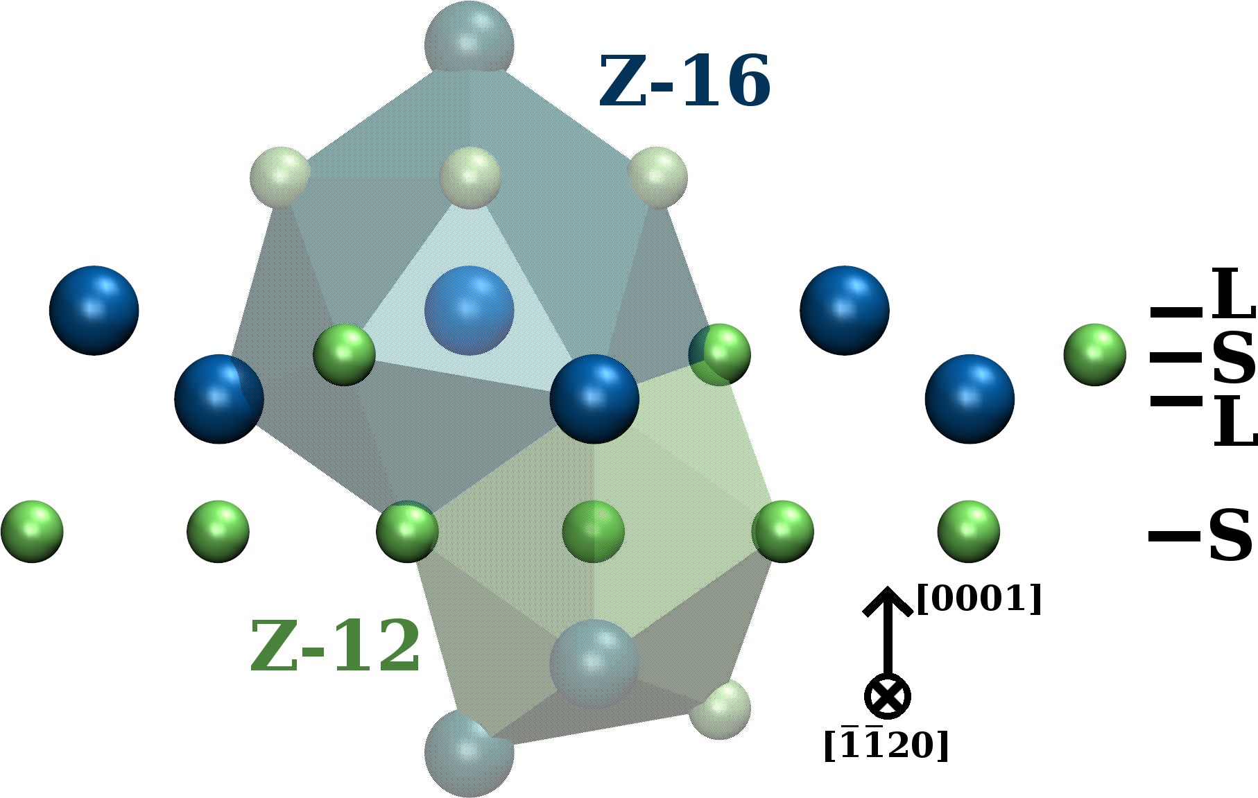
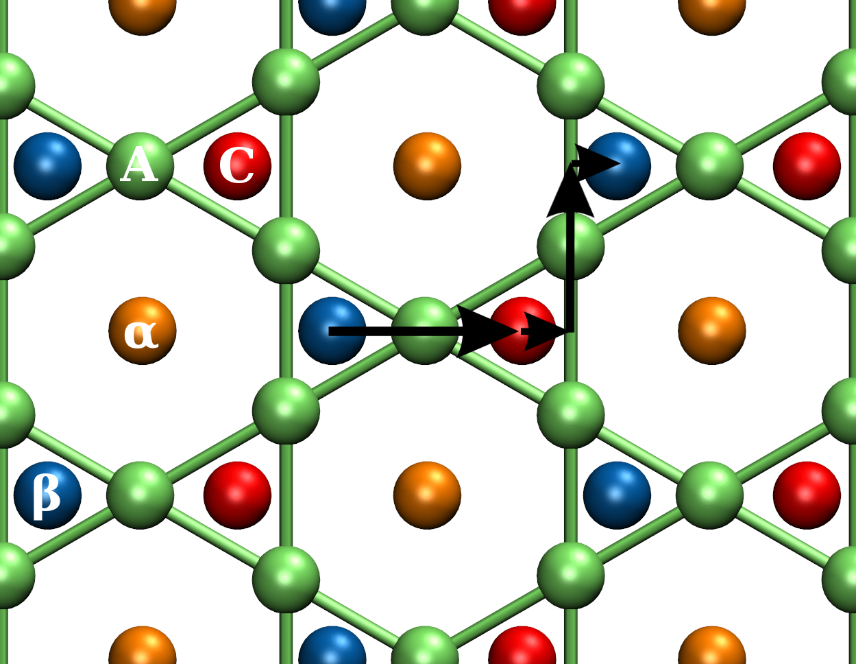
The crystal structure of the Laves phases comprises two-third polyhedra with coordination number =12 and one-third =16 polyhedra, occupied preferably by small (S) and large (L) atoms, respectively. It consists of a close-packed stacking of atomic layers of the -type in the Schäfli notation known as Kagomé layer and a puckered triple layer of L-S-L atoms along the 0001 direction in the hexagonal (h) representation (see Fig. 1) or along the 111 direction in the cubic (c) representation. The interlayer spacing within the puckered layer is approximately one third of that between the triple layer and the Kagomé layer. The atomic layers can be centered on either of the three high-symmetry points which are related by the Shockley Burgers vectors -h or -c as shown in Fig. 1. In the C14-Fe2Nb Laves phase, the Fe atoms correspond to S atoms on 2a and 6h sites with =12 and the Nb atoms correspond to L atoms on 4f sites with =16.
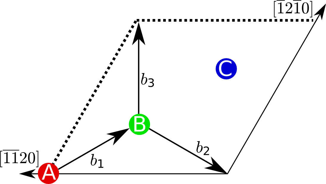
The stacking sequence needs to fulfill certain requirements in order to achieve close packing: the lower part of the triple layer occupies the center of the Kagomé layer while the middle sublayer occupies one of the two other high symmetry points. This results in two variants of the triple layer, and its reflection . The top layer is centered on the remaining high symmetry point. Depending on the centering of the Kagomé layer, the quadruple layer can be of type , , or their reflections , , . The quadruple layer, e.g., corresponds to an Ac stacking sequence. (Small atoms on the A, B and C points are denoted as a, b, and c while large atoms on these sites are referred to as , and .) The various stacking sequences of quadruple layers give rise to the Laves phase polytypes C14, C15 and C36 (see Ref. Kumar2004, for a detailed discussion) with the three shortest repeating periods (h), (c) and (h).
The experimentally observable slip in Laves phases occurs mostly in the basal plane Allen1972 ; Kumar1994 ; Chisholm2005 . The three known basal deformation mechanisms for Laves phases are direct slip, synchroshear Hazzledine1993 and undulating slip Zhang2011 . Their relative importance is determined by the generalized stacking fault energy (SFE) curve Tadmor2003 ; VanSwygenhoven2004 . While hardly accessible by experiment, the generalized SFE can be determined by atomistic calculations using electronic-structure methods Moeller2018 . For several Laves phase compounds, the generalized SFE has been determined by density-functional theory (DFT) calculations Vedmedenko2008 ; Ma2013 ; Ma2014 . For the technologically important C14-Fe2Nb Laves phase Voss-11 , however, atomistic insight to the governing mechanism of plastic deformation is still missing.
In this study, we perform DFT calculations to determine the generalized SFE curves in the C14-Fe2Nb Laves phase. We compare the deformation by direct slip, synchroshear and undulating slip in defect-free, stoichiometric C14-Fe2Nb, followed by an analysis of the influence of off-stoichiometric compositions due to vacancy or antisite defects. In addition we assess the possibility of polytypic transformations from C14 to C15 and C36 by successive transformation via intermediate SF configurations.
II Methodology
The DFT calculations presented in this work were performed with the VASP software (version 5.4) Kresse1996 ; Kresse1996b ; Kresse1999 using the projector-augmented wave method Bloechl-94 . The generalized gradient approximation to the exchange-correlation functional Perdew-96 and pseudo-potentials with semicore states were employed. A planewave cut-off energy of 450 eV and a -point spacing of 6 Å-1 was required to converge the total energies to less than 1 meV/atom. A supercell consisting of 24 atomic layers (36 atoms) was used in the calculation of the bulk SFE. The initial magnetic configuration was set to the energetically most favorable arrangement for the Fe2Nb C14 Laves phase, i.e. (UD)/(UD)/U on the 2a/6h/4f sites, as determined previously Ladines2015 . No constraints on the spins were applied during the electronic self-consistency. The reference structure was obtained by optimizing the lattice parameters and the atomic positions of the bulk C14-Fe2Nb Laves phase. For the deformation along the generalized SFE curve we use sheared periodic boundary conditions that vary as a function of the deformation parameter Vedmedenko2008 . During the deformation, the ionic positions were allowed to relax while the deformed simulation cell was kept fixed. For the simulations with vacancy and antisite defects, a supercell (96 atoms) was used to avoid interaction of the points defects with their periodic boundary image.
III Results and discussion
III.1 Basal deformation of stoichiometric C14-Fe2Nb
III.1.1 Deformation mechanisms
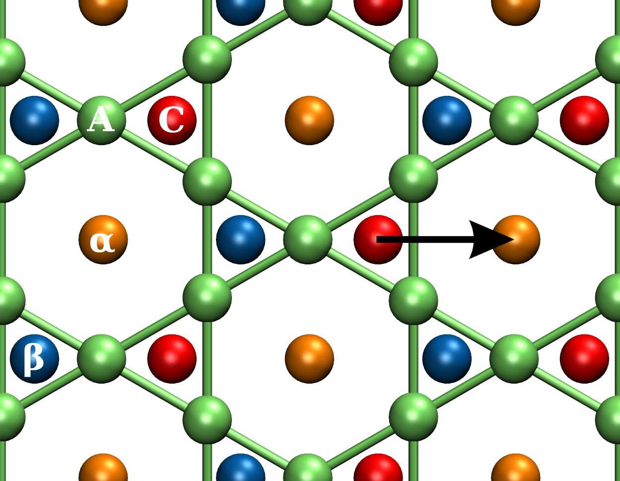
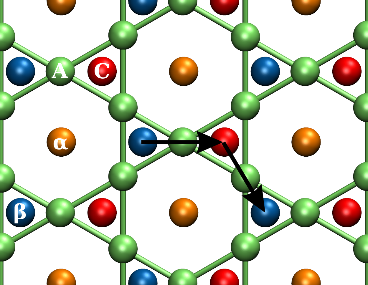
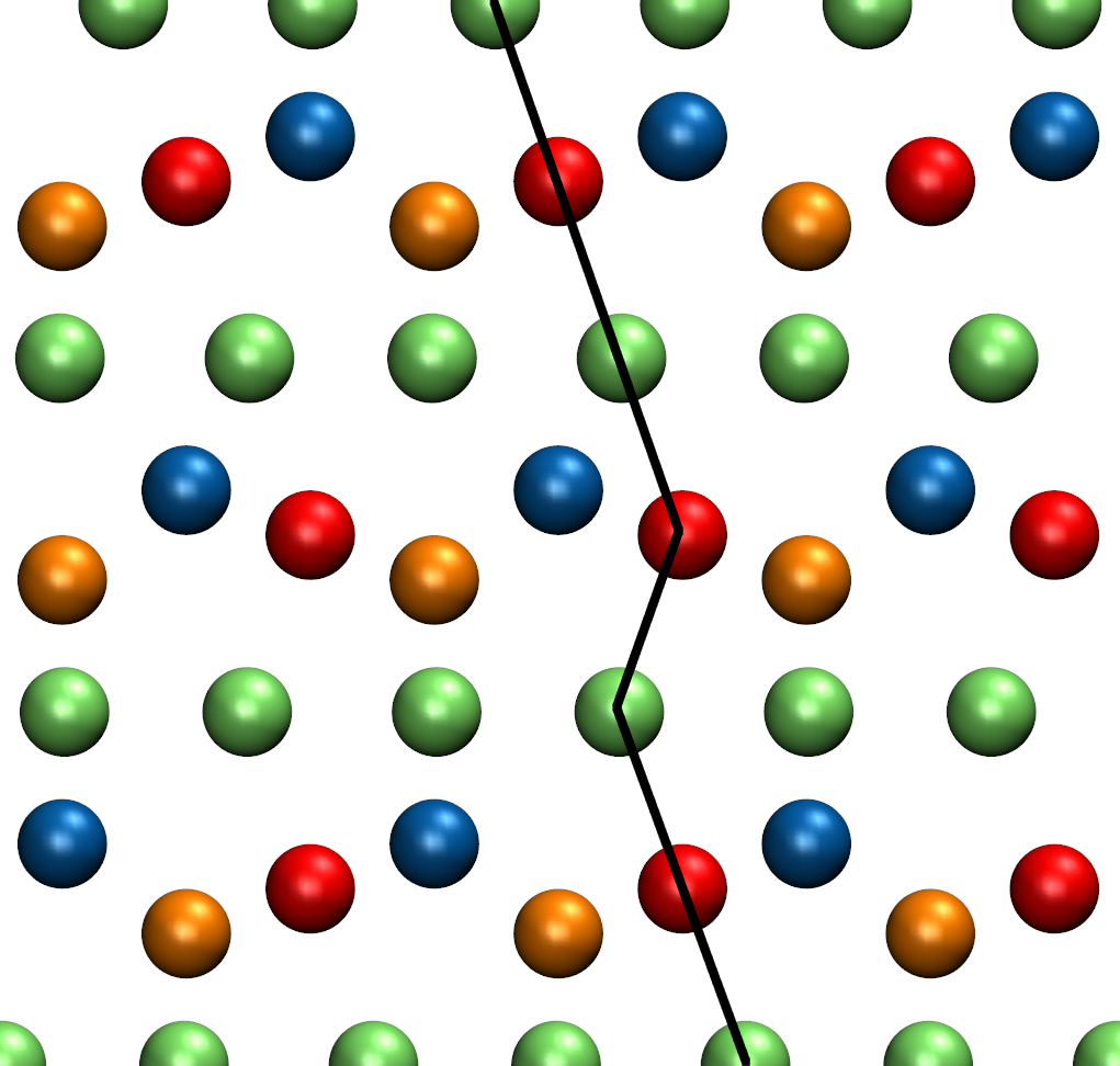
There are at least three basal deformation modes in Laves phases, shown schematically in Fig. 2: (i) The most apparent mechanism is direct slip between the Kagomé and the triple layer with Burgers vector -h. (ii) The synchroshear slip mechanism involves a synchronous displacement of the middle and top layer by -h and -h, respectively Hazzledine1993 . (iii) The undulating slip mechanism is a deformation process which involves crystallographic slip and atomic shuffling. This slip mechanism was shown to have a lower energy barrier in the Cr2Nb system compared to the previously discussed deformation modes Zhang2011 .
III.1.2 Generalized SFE curves for C14-Fe2Nb
Experimental analysis of deformed Fe2Nb samples identified SF structures as remainders of basal slip deformation Takata2008 ; Slapakova2016 and suggested synchroshear as dominant deformation process. However, undulating slip cannot be excluded as the resulting local C15 stacking sequence is the same for synchroshear and undulating slip (see Fig. 2). Here, we determine the most favorable basal deformation mechanism in C14-Fe2Nb by DFT calculations of the energy barrier along the generalized SFE curves shown in Fig. 3.
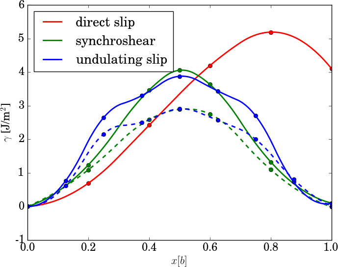
Direct slip involves rather small energies in the initial stage due to the large free volume between the Kagomé layer and the triple layer which then increase as the Fe atoms in the Kagomé layer approach the Nb atoms in the adjacent layer. The energy barrier for direct slip, given by the maximum of the generalized SFE curve, is the largest among the three deformation mechanisms. This deformation results in a metastable configuration which may further develop to a stable configuration through a similar slip along the two other Burgers vectors. Synchroshear and undulating slip, in contrast, lead to a stable SF with a formation energy of 50 mJ/m2. The energy barrier to arrive at this stable SF is reported in Fig. 3 for both, relaxed and unrelaxed configurations. For the unrelaxed configurations, the undulating slip has the lowest energy barrier of the three deformation modes. Upon relaxation, the synchroshear and undulating slip lead to the same unstable SF configuration at the maximum of the generalized SFE curve and hence exhibit the same energy barrier of approximately 3 J/m2. This finding is in line with the experimentally observed SF configuration after deformation Takata2008 ; Slapakova2016 . Similar results were obtained recently with a classical potential for the case of C14-Mg2Ca Guenole-19 .
Overall, the rather large barriers indicate that plastic deformation of the C14-Fe2Nb Laves phase by dislocation nucleation in the basal plane is associated with large stresses. This raises the questions (i) if the barriers can be reduced, e.g., by changing the chemical composition (see Sec. III.2), (ii) if further processes are activated by the required large stresses (see Sec. III.3) and (iii) if the experimentally observed SF in C14-Fe2Nb could be remains of other, not yet identified processes.
III.2 Off-stoichiometric softening
III.2.1 Formation energy of point defects in C14-Fe2Nb
Many Laves phases are known to form also at off-stoichiometric compositions Thoma1995 . The deviation from the 2:1 composition is attributed to vacancies or antisite atoms, primarily of the smaller atom. These point defects are known to have profound impact on the mechanical properties Liu2000 . The vacancy formation-energy
| (1) |
and the antisite formation energy
| (2) |
are computed from the difference in the heat of formation obtained by DFT as outlined in the Appendix. is the fraction of defects to the number of atoms in the supercell. The heat of formation of the supercells with and without defect are computed with respect to the bcc ground-states of Fe and Nb. (A previously reported simpler accounting for changes in chemical composition due to defect formation leads to qualitatively comparable results Ladines-17 .)
| site | (eV) | (eV) |
|---|---|---|
| 2a (Fe) | 2.71 | 0.60 |
| 6h (Fe) | 2.57 | 0.87 |
| 4f (Nb) | 2.77 | 1.33 |
Our DFT calculations, compiled in Tab. 1, show that the formation energies of the different antisite defects are considerably lower than all vacancy formation energies. We therefore expect that antisite defects are the dominant intrinsic defects in Fe2Nb. This is consistent with the experimentally observed absence of vacancies in C14-Fe2Nb Zhu1999 .
The energetic ordering of the antisite defects in Tab. 1 is related to the size of the Fe/Nb atoms on one hand and the Z12/Z16 coordination polyhedra on the other hand: The DFT results indicate that it is energetically favorable by about at least 0.5 eV to squeeze a comparably larger Nb atom in an empty Z12 polyhedron of a removed Fe atom than to fill an empty Z16 polyhedron of a removed Nb atom with a comparably smaller Fe atom.
III.2.2 Influence of point defects on generalized SFE
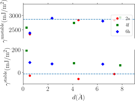
An early work on C14-Fe2Nb reported that the antisite defects cause a hardening on both sides of the 2:1 stoichiometry Zhu1999 . More recent works made contrasting observations of progressive softening for off-stoichiometric compositions Voss2009 ; Takata2016 . This softening was suggested to arise from the free volume generated by the vacancy or antisite which facilitates the motion of synchro-Shockley dislocations Kumar2004 ; Chu1994 . In order to shed light on these contrasting findings, we compute the influence of vacancy and antisite defects on the barrier for plastic deformation in C14-Fe2Nb. In particular, we compute the formation energy of the unstable and stable SF ( and in Fig. 3) with either of these two point defects present in different distances from the SF plane.
Our calculations, compiled in Fig. 4, show that nearly all defects increase the formation energy of the stable stacking fault () and decrease the energy barrier for synchroshear (). The only exception with a notably increased barrier is the antisite defect on Fe sites in 7.5Å distance from the SF plane. The origin of this exception is the convergence to a magnetic state that is different from the one of the unsheared structure. The variation of the SF energy with distance for the individual defects shows that only vacancies on Fe sites are weakly attracted to the SF plane while all other vacancy and antisite defects are weakly repelled. From the overall rather small thermodynamic driving forces for segregation we expect that the local site occupation is not considerably affected by the presence of the stable SF.
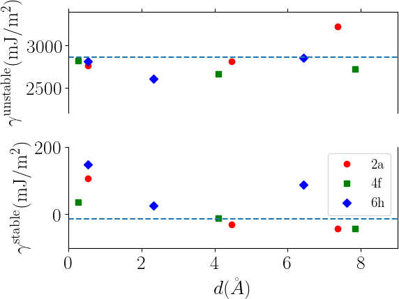
In summary, our calculations show that deviations from the 2:1 composition due to vacancies or due to antisite defects lead to a softening of C14-Fe2Nb on both sides of the stoichiometry due to a reduced energy barrier for shearing. This finding explains the recent experimental observations Voss2009 ; Takata2016 of softening for off-stoichiometric compositions.
III.3 Polytypic transformations
The stresses that are needed to overcome the computed barriers for basal slip (Sec. III.1) are so large that one might expect that other processes are initiated, too. A particularly likely candidate are stress-induced transformations that are known from other Laves phase compounds Stein2005 . Here, we compute the energy barriers of polytypic transformation between C14, C15 and C36 Laves phases by successive synchroshear, see Fig. 5.
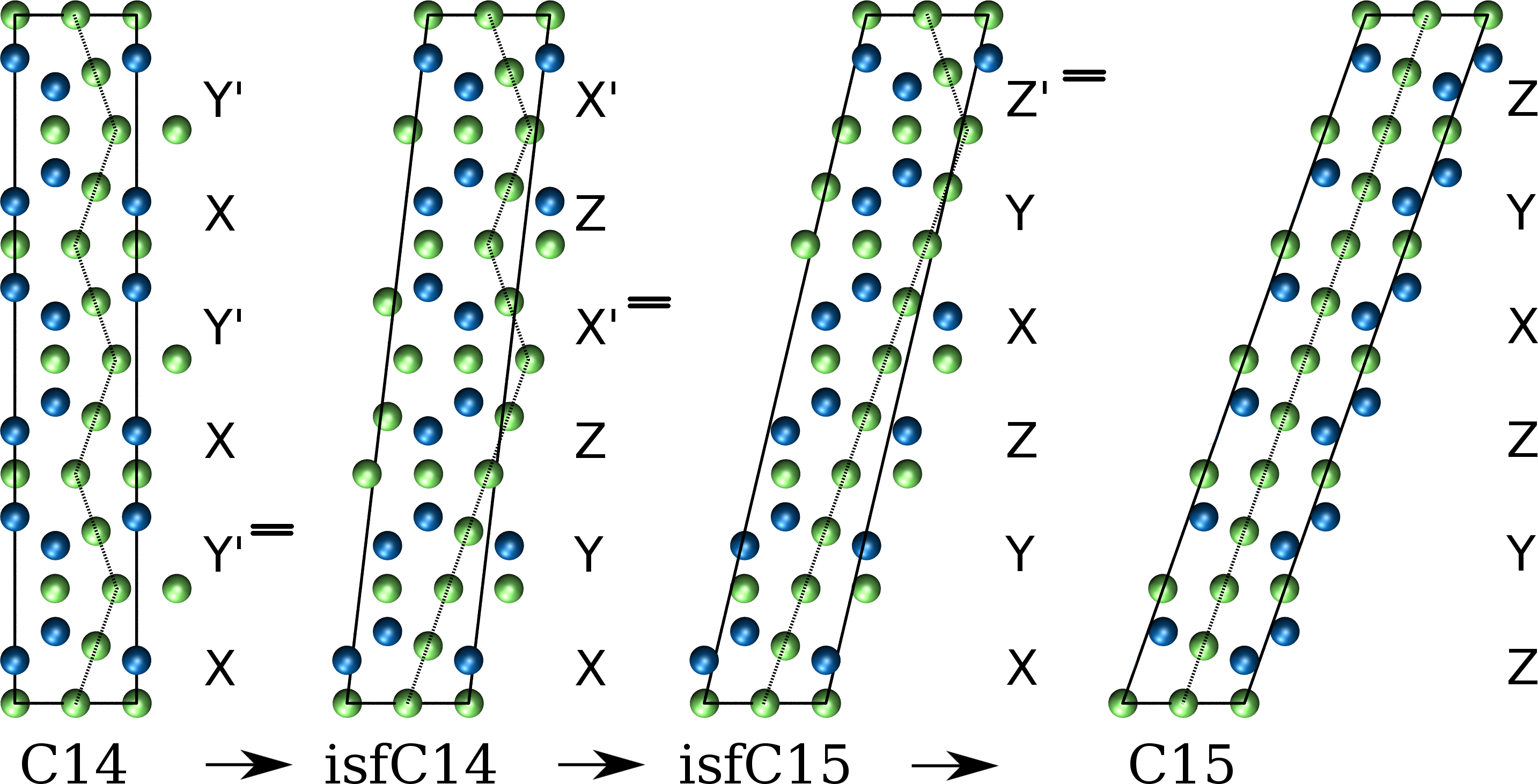
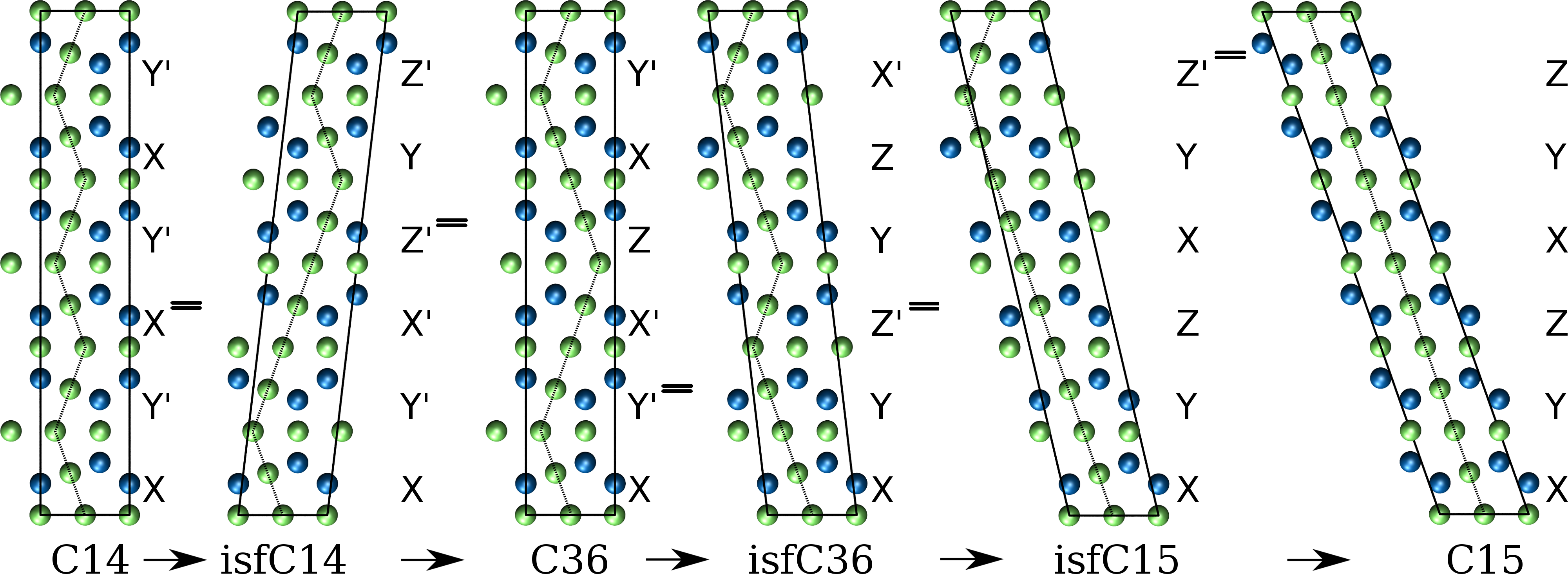
A synchroshear deformation can be seen as propagation of two Shockley dislocations through the quadruple layer which leads to a macroscopic shear strain. The Burgers vector of the Shockley dislocations can be one of those shown in Fig. 1. If the layer of small atoms in the triple layer moves along , the upper layer of large atoms must move in synch either along or . This deformation transforms a quadruple layer to or vice versa. Applying an equal number of these three equivalent Burgers vectors can lead to an alternative polytypic transformation without macroscopic strain Kumar2004 . A transformation between Laves phase polytypes can also be realized if the number of and synchroshear steps are equal. This is the case for the C14C36 transformation shown in Fig.5(b). Therefore, it is possible to transform the C14 structure to the C15 structure in two ways Vedmedenko2008 by a series of synchroshear steps as illustrated in Fig. 5. In the plastic deformation of C14-Fe2Nb, an already formed stable SF could transform further by successive synchroshear steps that eventually lead to a precipitate of C15 or C36.
We compare the formation of a new stable SF to a further synchroshear of an existing SF, in terms of the energy profile along the polytypic transformation by successive synchroshear. We used unrelaxed atomic structures along the transformation path that we compare to the unrelaxed structures of the generalized SFE for basal slip in Fig. 3. From our calculations for the SFE we expect that including the structural relaxation would lead to an overall scaling that would not alter our conclusions.
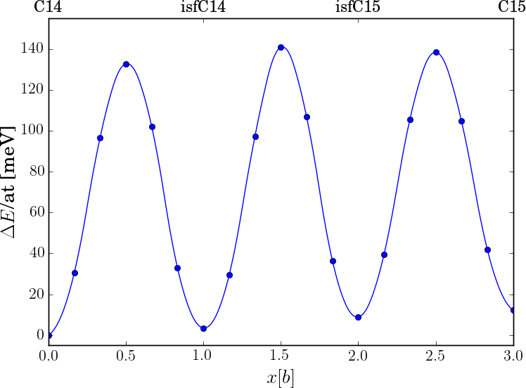
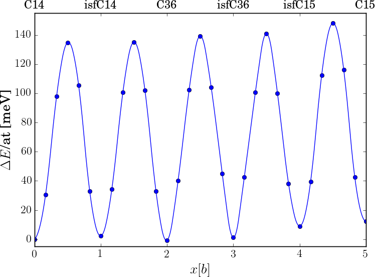
In Fig. 6 we plot the computed change in energy with respect to the initial C14-Fe2Nb for the corresponding configurations. The first insight from our DFT results is that all intermediate stable states of the polytypic transformation, i.e. the Laves phases as well as their intrinsic stacking faults, are very close in energy within a range of less than 20 meV per atom. The formation energy of the SF in C36 is negative since C36 is predicted to be more energetically favorable in our spin-polarized DFT calculations. The correct prediction of the C14 ground state requires to extend the DFT calculations to a proper treatment of paramagnetism Slapakova-2020 which would then be too computationally involved for the large supercells required for this work. The second insight is that the energy barriers between the intermediate stable states of the synchroshear series are almost identical ( 140 meV/at 4 J/m2). Moreover, they are very similar to the energy barrier for a single synchroshear or undulating slip in the generalized SFE curve of C14-Fe2Nb for unrelaxed atomic positions (Fig.3). This indicates that pressures which lead to the formation of an intrinsic SF in C14-Fe2Nb may also initiate a polytypic transformation of C14 to C15 or C36 by further transforming already existing SFs.
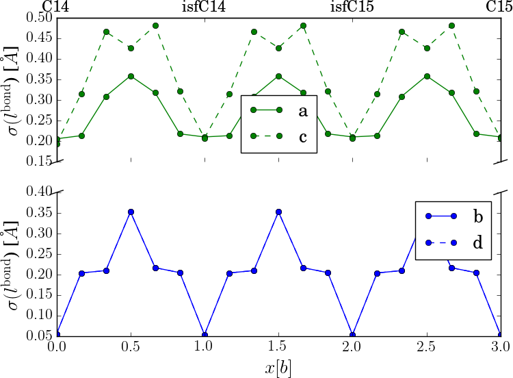
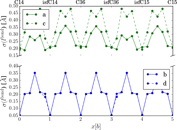
The energy profile along the polytypic transformation by a series of synchroshear steps can be rationalized in terms of the corresponding deformation of the Z12 and Z16 Frank Kasper polyhedra. A measure of this deformation is the change in the nearest-neighbour bond-lengths, , of the S and L atoms in the synchrosheared quadruple layer shown in Fig. 7. The change in bond lengths along the synchroshear steps is similar for the S and L atoms in in the quadruple layer and reaches values of nearly 0.5 Å. This considerable change is directly related to the energy increase at the transition point of the energy profile in Fig. 6.
IV Conclusions
We perform DFT calculations on the role of different basal slip mechanisms for the plastic deformations of the C14-Fe2Nb Laves phase. The generalized stacking-fault energy curves show that synchroshear and undulating slip pass the same transition state with an energy barrier of 3 that is considerably lower than direct slip. The experimentally observed stacking fault configurations are in line with the final structures of both, synchroshear and undulating slip. However, the large energy barriers for the considered mechanisms and the rather low formation energy of stable SF in C14 may indicate the existence of not yet considered mechanisms that lead to the experimentally observed SF configurations.
Our DFT calculations for the stable and unstable SF in the presence of vacancies and antisite defects show that the barrier for synchroshear is decreased. This finding explains the experimentally observed softening of C14-Fe2Nb by off-stoichoimetric compositions on both sides of the 2:1 composition.
In order to assess the possibility of polytypic transformations, we compute the energy profile of the transformation from C15 to C14 and C36 by a series of synchroshear deformations. The energy barriers are very similar for the different steps of the deformation series and moreover very similar to synchroshear and undulating slip. This indicates that the pressures which lead to plastic deformation of C14-Fe2Nb by stacking fault formation can also initiate polytypic transformation of C14 to C15 or C36 through successive synchroshear of existing SF.
Appendix: Formation energy of point defects
For the energetic ranking of the different point defects in C14-Fe2Nb, we compute the formation energy per atom of a general structure with Fe atoms and Nb atoms as
| (3) |
where , and are the DFT total energies of the respective general structure and the energetically most favorable bcc structure of Fe and Nb. This choice corresponds to the chemical potential of the DFT convex hull at T=0K. The superscripts denote the number of Fe and Nb atoms in the DFT simulation cell. The bcc simulation cells are assumed to contain one atom. The formation energy per atom of ideal C14-Fe2Nb without defects is given by
| (4) |
and referred to as in Eqs. 1 and 2. The formation of vacancies and antisite defects in C14-Fe2Nb alters the chemical composition. In order to compute the defect formation energy, we need the energy difference between ideal bulk and the defect structure plus additional terms that balance the total number of atoms for each species.
For vacancies, the formation energy per atom of a supercell structure with a missing Fe atom (’C14vacFe’) is given by
| (5) |
The formation energy per vacancy
| (6) |
can be rewritten in terms of the structure formation energy (per atom) as
| (7) | |||||
which by comparison to Eqs. 4 and 5 reduces to
| (8) |
With the fraction of the number of defects to the number of atoms in the defect-free supercell of we obtain
| (9) |
as formation energy of an Fe vacancy, and correspondingly for a Nb vacancy.
For an antisite defect, e.g. an Fe atom on a Nb site (’C14antiFe’), the formation energy per antisite defect is
| (10) |
which can be rewritten as
| (11) | |||||
Following the procedure above we obtain
| (12) |
that reduces to
| (13) |
and correspondingly for Nb atoms on Fe sites.
Acknowledgements
We acknowledge fruitful discussions with Ali Zendegani and Tilmann Hickel. This work was funded by the German Research Society DFG (project number 289654611).
References
- (1) A. Sinha, Topologically close-packed structures of transition metal alloys, Progress in Materials Science 15 (1972) 81.
- (2) F. Stein, A. Leineweber, Laves phases: a review of their functional and structural applications and an improved fundamental understanding of stability and properties, Journal of Materials Science 56 (2021) 5321.
- (3) B. Seiser, R. Drautz, D. G. Pettifor, TCP phase predictions in Ni-based superalloys: Structure maps revisited, Acta materialia 59 (2011) 749.
- (4) B. Seiser, T. Hammerschmidt, A. N. Kolmogorov, R. Drautz, D. G. Pettifor, Theory of structural trends within 4d and 5d transition metals topologically close-packed phases, Physical Review B 83 (2011) 224116.
- (5) T. Hammerschmidt, A. Bialon, D. Pettifor, R. Drautz, Topologically close-packed phases in binary transition-metal compounds: matching high-throughput ab initio calculations to an empirical structure map, New Journal of Physics 15 (2013) 115016.
- (6) A. Ladines, T. Hammerschmidt, R. Drautz, Structural stability of Fe-based topologically close-packed phases, Intermetallics 59 (2015) 59.
- (7) J. D. Livingston, Laves-phase superalloys?, physica status solidi (a) 131 (1992) 415.
- (8) M. Heggen, L. Houben, M. Feuerbacher, Plastic deformation mechanism in complex solids, Nature Materials 9 (2010) 332–336.
- (9) Y. Zhang, W. Zhang, B. Du, W. Li, L. Sheng, H. Ye, K. Du, Shuffle and glide mechanisms of prismatic dislocations in a hexagonal -type laves-phase intermetallic compound, Phys. Rev. B 102 (2020) 134117.
- (10) K. Kumar, P. Hazzledine, Polytypic transformations in Laves phases, Intermetallics 12 (2004) 763.
- (11) C. W. Allen, P. Delavignette, S. Amelinckx, Electron microscopic studies of the Laves phases TiCr2 and TiCo2, physica status solidi (a) 9 (1972) 237.
- (12) K. Kumar, D. Miracle, Microstructural evolution and mechanical properties of a Cr-Cr2Hf alloy, Intermetallics 2 (1994) 257.
- (13) M. F. Chisholm, S. Kumar, P. Hazzledine, Dislocations in complex materials, Science 307 (2005) 701–703.
- (14) P. Hazzledine, P. Pirouz, Synchroshear transformations in Laves phases, Scripta Metallurgica et Materialia 28 (1993) 1277 – 1282.
- (15) W. Zhang, R. Yu, K. Du, Z. Cheng, H. Zhu, J.and Ye, Undulating slip in Laves phase and implications for deformation in brittle materials, Physical Review Letters 106 (2011) 165505.
- (16) E. Tadmor, S. Hai, A peierls criterion for the onset of deformation twinning at a crack tip, Journal of the Mechanics and Physics of Solids 51 (2003) 765.
- (17) H. Van Swygenhoven, P. M. Derlet, A. G. Froseth, Stacking fault energies and slip in nanocrystalline metals, Nature Materials 3 (2004) 399.
- (18) J. Möller, M. Mrovec, I. Bleskov, T. Hammerschmidt, R. Drautz, C. Elsässer, J. Neugebauer, T. Hickel, E. Bitzek, On 110 planar faults in strained bcc metals - origins and implications of a commonly observed artefact of classical potentials, Physical Review Materials 2 (2018) 093606.
- (19) O. Vedmedenko, F. Rösch, C. Elsässer, First-principles density functional theory study of phase transformations in NbCr2 and TaCr2, Acta Materialia 56 (2008) 4984 – 4992.
- (20) L. Ma, T.-W. Fan, B.-Y. Tang, L.-M. Peng, W.-J. Ding, Ab initio study of I2 and T2 stacking faults in C14 Laves phase MgZn2, The European Physical Journal B 86 (2013) 188.
- (21) L. Ma, R.-K. Pan, S.-C. Zhou, T.-P. Luo, D.-H. Wu, T.-W. Fan, B.-Y. Tang, Ab initio study of stacking faults and deformation mechanism in C15 Laves phases Cr2X (X = Nb, Zr, Hf), Materials Chemistry and Physics 143 (2014) 702.
- (22) S. Voß, M. Palm, F. Stein, D. Raabe, Phase equilibria in the Fe-Nb system, Journal of Phase Equilibria and Diffusion 32 (2011) 97–104.
- (23) G. Kresse, J. Furthmüller, Efficiency of ab-initio total energy calculations for metals and semiconductors using a plane-wave basis set, Computational Materials Science 6 (1996) 15.
- (24) G. Kresse, J. Furthmüller, Efficient iterative schemes for ab initio total-energy calculations using a plane-wave basis set, Physical Review B 54 (1996) 11169.
- (25) G. Kresse, D. Joubert, From ultrasoft pseudopotentials to the projector augmented-wave method, Physical Review B 59 (1999) 1758.
- (26) P. E. Blöchl, Projector augmented-wave method, Physical Review B 50 (1994) 17953.
- (27) J. P. Perdew, K. Burke, M. Ernzerhof, Generalized gradient approximation made simple, Physical Review Letters 77 (1996) 3865.
- (28) N. Takata, S. Ishikawa, T. Matsuo, M. Takeyama, Transmission electron microscopy of Fe2Nb Laves phase with C14 structure in Fe-Nb-Ni alloys, MRS Online Proceedings Library 1128 (2008) 806.
- (29) M. Slapakova Pokova, S. Voß, K. Kumar, C. Liebscher, F. Stein, Transmission electron microscopy of deformed Laves phase NbFe2, in: European Microscopy Congress 2016 Proceedings, Wiley-VCH, 2016, pp. 263–264.
- (30) J. Guenole, F.-Z. Mouhiba, L. Huber, B. Grabowski, S. Korte-Kerzel, Basal slip in Laves phases: The synchroshear dislocation, Scripta Materialia 166 (2019) 134.
- (31) D. Thoma, J. Perepezko, A geometric analysis of solubility ranges in Laves phases, Journal of Alloys and Compounds 224 (1995) 330.
- (32) C. Liu, J. Zhu, M. Brady, C. McKamey, L. Pike, Physical metallurgy and mechanical properties of transition-metal Laves phase alloys, Intermetallics 8 (2000) 1119.
- (33) A. Ladines, R. Drautz, T. Hammerschmidt, Ab-initio study of C and N point defects in the C14-Fe2Nb phase, Journal of Alloys and Compounds 693 (2017) 1315–1322.
- (34) J. Zhu, L. Pike, C. Liu, P. Liaw, Point defects in binary Laves phase alloys, Acta Materialia 47 (7) (1999) 2003 – 2018.
- (35) S. Voß, F. Stein, M. Palm, D. Grüner, G. Kreiner, G. Frommeyer, D. Raabe, Composition dependence of the hardness of Laves phases in the Fe-Nb and Co-Nb systems, MRS Online Proceedings Library 1128 (2008) 805.
- (36) N. Takata, H. Ghassemi-Armaki, M. Takeyama, S. Kumar, Nanoindentation study on solid solution softening of Fe-rich Fe2Nb Laves phase by Ni in Fe-Nb-Ni ternary alloys, Intermetallics 70 (2016) 7 – 16.
- (37) F. Chu, D. Pope, Deformation of C15 laves phase alloys, Materials Research Society Symposium Proceedings 364 (1994) 1197.
- (38) F. Stein, M. Palm, G. Sauthoff, Structure and stability of Laves phases part II - Structure type variations in binary and ternary systems, Intermetallics 13 (2005) 1056.
- (39) M. Slapakova, A. Zendegani, C. Liebscher, T. Hickel, J. Neugebauer, T. Hammerschmidt, A. Ormeci, Y. Grin, G. Dehm, S. Kumar, F. Stein, Atomic scale configuration of planar defects in the Nb-rich C14 Laves phase NbFe2, Acta Mater. 183 (2020) 362–376.