The effects of a passive Bi-Polar Grid (BPG) on
Ion Back-Flow (IBF) and Resolution
Abstract
Time Projection Chambers (TPC)s are excellent tracking detectors for high multiplicity events and can intrinsically be high-rate, but are limited by the ions created in their avalanche stage. GEMs and Micromegas can reduce IBF through their geometry and -field ratios, but these can lead to gain fluctuations and still leave IBF as the dominant source of space charge. An active BPG can block all IBF ions, but their slow drift speed creates too much dead time. A passive BPG will overcome this limitation by using an external -field to allow the electrons to pass through while still blocking all ions. Since the grid changes the electron’s trajectory, a loss of resolution will occur. The trajectory is shifted symmetrically along the wires so the wire alignment with respect to the detection pads is a specific question not studied before. We present completed IBF analysis from data collected at Weizmann Institute of Science (WIS), along with an intro to our test on wire resolution.
1 Gating Grids
A passive BPG with can provide -field ratios without creating fluctuations and would eliminate dead time by constantly being opaque to ions while exploiting an external magnetic -field to remain transparent to electrons.
| (1.1) |
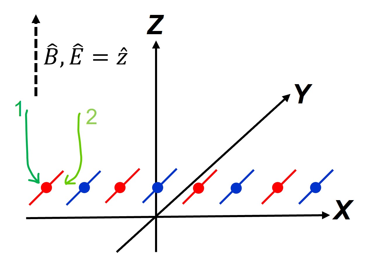
Charges follow the Langevin equation and lighter electrons will experience a continuous “push" allowing them to pass between the wires. Electrons coming from above the wire will get their 1st push along the length of the wire: . Then they get a 2nd weaker push which allows them to get past the wires: . Fig. 1 shows these effects along with the distortion both pinched and shifted in their y-position. Acceptable electron transparency with 0% ion transparency has been demonstrated by previous groups [1].
The general equation for the charge velocity in a gas as a function of and fields is given by
| (1.2) |
where is the charge mobility with as the average time between collisions. is the cyclotron frequency. Defining angle between and the positive x-direction gives . Together with leads to
| (1.3) |
If the BPG wires aren’t uniformly spaced along their tensioned direction an component will be present and the charge velocity equations become
| (1.4) |
where . In both cases, the velocities of main interest for ion blocking and electron transparency and are strongly dependent on . For electrons and the velocities will follow the -field and ignore the local -field of the BPG. For ions the converse is true.
2 Weizmann IBF Measurements
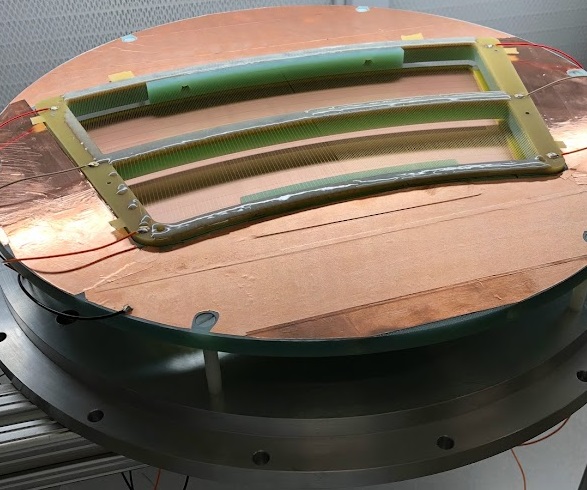
Ion and electron transparencies, as a function of -field and volts on a linear BPG, were measured at Weizmann. A detector with MWPC gain wires was constructed. A strong 55Fe X-Ray source was used and picoAmmeters were implemented to measure the small changes in current as the grid was slowly closed to ions. A mesh was used to help create a uniform drift field, as seen in Fig. 2, and to create a region where the -field above-to-below ratios can be better exploited.
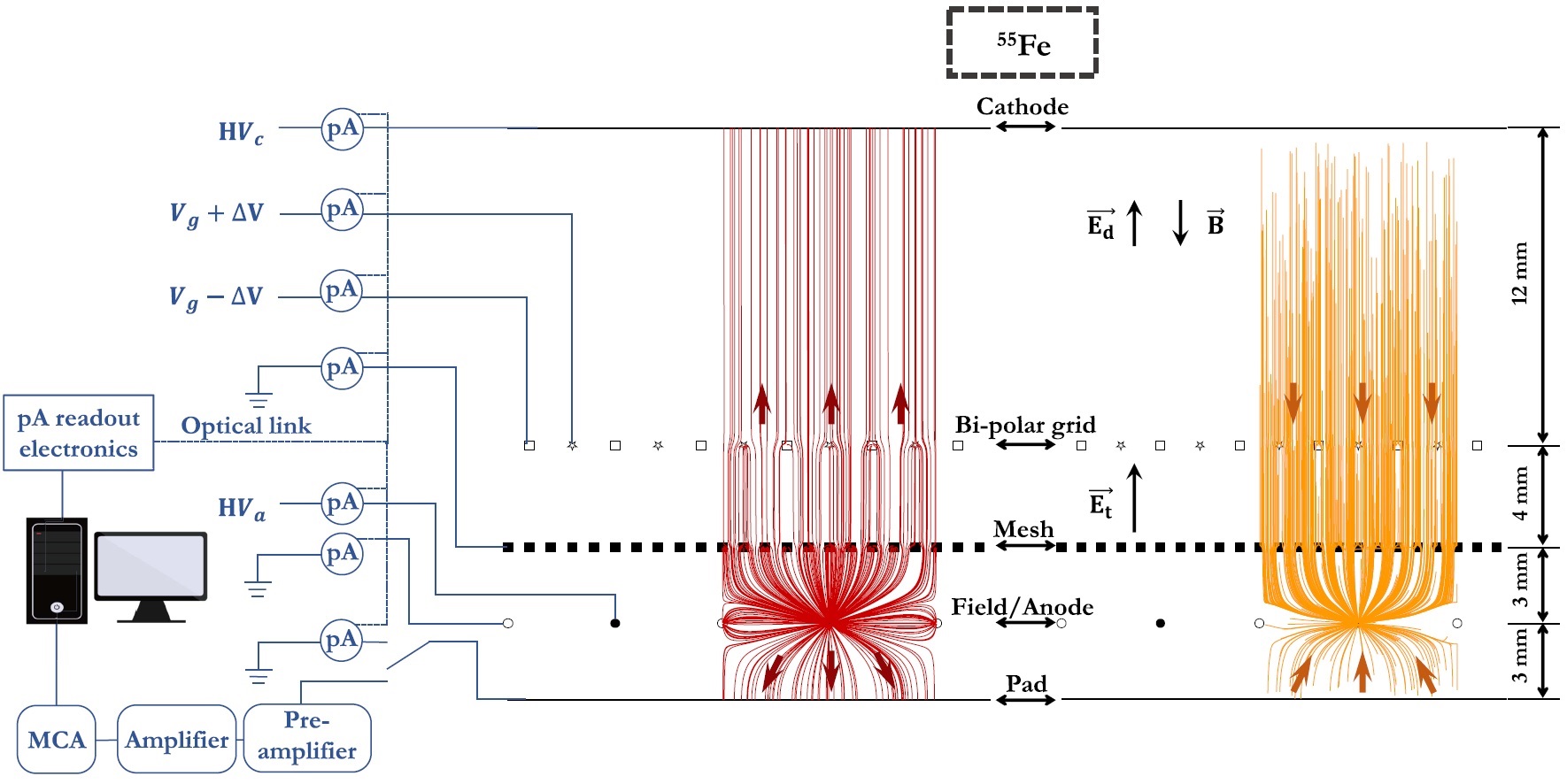
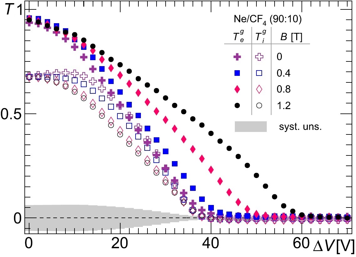
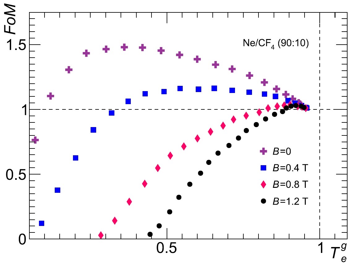
Field ratios were varied measuring the electron and ion transparencies from the BPG and mesh . Increased grid ratios meant decreased mesh ratios pulling more ions through it. requires an increased gain, which creates more IBF. A Figure of Merit (FoM) was constructed to quantify the effectiveness of the BPG [3]. 1st term comes from ratios, where higher ratios can extract more ions from the gain region. 2nd term compensates for loss of primaries creating more IBF ions. Fig. 3 shows an example for transparencies and FoM.
| (2.1) |
3 BPG Resolution Distortion
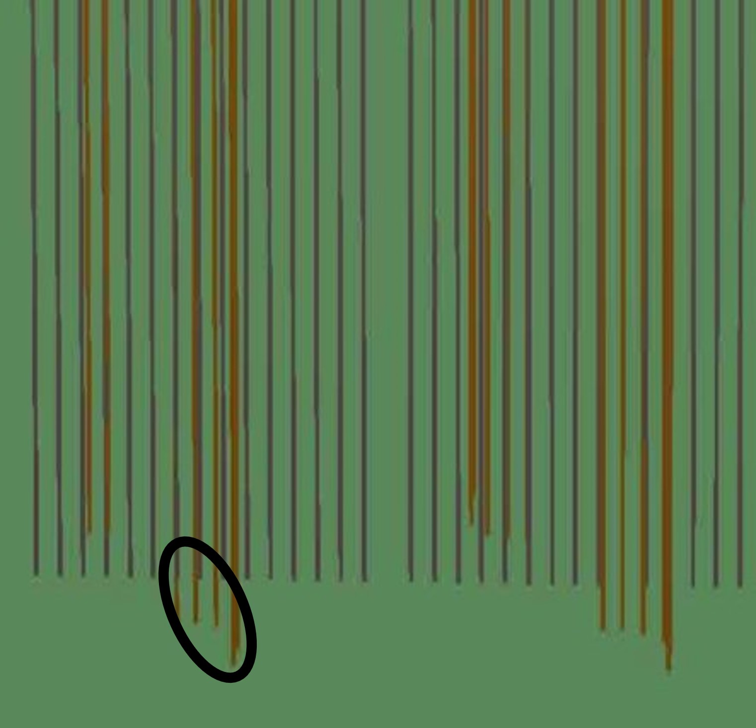
From the equations of motion, and as seen in Fig. 1, the electrons fall "out of plane", and alternating wires "pinch" them together, hurting resolution. The error is cyclical with the same periodicity as the wires. These recurring shifts are known as Differential Non-Linearity (DNL), and can be corrected. Segmented pads are used to spread out the electron cloud charge collection with finer detail in order to get a more precise track position measurement.
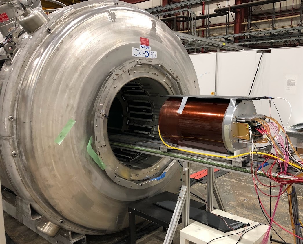
Zig-zag pads [4], which themselves have DNL-corrected error due to their shape, are used. From the grid’s symmetric shift, perhaps BPG’s distortions will average out over the full particle track, regardless of the wire’s position with respect to the radial zig-zags. However, if the grid is aligned with the pads then their independent DNLs might combine for better resolution. A BPG with 2 linear and 2 radial wire configurations is placed above the pad-plane and goes inside a prototype TPC. We’ve taken it to Argonne National Lab (ANL) to test this hypothesis (Fig. 4).
4 Conclusion
The passive BPG source test demonstrates ion blocking with high electron transparency. The ANL test showed excellent resolution results and a paper with the full test description and analysis will soon be published.
References
- [1] S.R. Amendolia et al., Influence of a magnetic Field on the gating of a TPC, NIM-A 234 (1985) 47.
- [2] V. Zakharov, P. Garg, T. Hemmick and K. Dehmelt, Study of a Passive Gating Grid for Ion Back Flow Suppression, J. Phys. Conf. Ser. 1498 (2020) 012 [1912.05005].
- [3] E. Shulga, V. Zakharov, P. Garg, T.K. Hemmick and A. Milov, Measurement of the ion blocking by the passive bipolar grid, IEEE Transactions on Nuclear Science 68 (2021) 59.
- [4] B. Azmoun et al., Design studies for a tpc readout plane using zigzag patterns with multistage gem detectors, IEEE Transactions on Nuclear Science 65 (2018) 1416.