A Security-aware Network Function Sharing Model for 5G Slicing
Abstract
Sharing Virtualized Network Functions (VNFs) among different slices in Fifth Generation (5G) is a potential strategy to simplify the system implementation and utilize 5G resources efficiently. In this paper, we propose a security-aware VNF sharing model for 5G networks. The proposed optimization model satisfies the service requirements of various slices, enhances slice security by isolating their critical VNFs, and enhances resource utilization of the underlying physical infrastructure. The model tries to systematically decide on sharing a particular VNF based on two groups of constraints; the first group of constraints is common assignment constraints used in the existing literature. The second group is the novel security constraints that we propose in this work; the maximum traffic allowed to be processed by the VNF and the exposure of the VNF to procedures sourced via untrusted users or access networks. This sharing problem is formalized to allow for procedure-level modeling that satisfies the requirements of slice requests in 5G systems. The model is tested using standard VNFs and procedures of the 5G system rather than generic ones. The numerical results of the model show the benefits and costs of applying the security constraints along with the network performance in terms of different metrics.
Index Terms:
5G Security, Network Slicing (NS), VNF Sharing, OptimizationI Introduction
5Gnetworks are visioned to support various applications and services with diversified requirements [1]. One distinct concept in 5G architecture is the Network Slicing (NS)which was not present in previous generations of cellular networks. NS enables 5G operators to deploy multiple logical networks on shared physical resources to serve traffic segments with different demands [2, 3]. This is achieved using different technologies integrated with 5G architecture such as, most notably, Network Function Virtualization (NFV) technology. NFV allows the deployment of Virtualized Network Functions (VNFs)in software or a virtualized environment on commodity hardware. Both NS and NFV help 5G operators to reduce the overall Capital Expenditure (CAPEX) and Operational Expenditure (OPEX) by deploying VNFs efficiently and flexibly to optimize the utilization of network resources [4].
In this paper, we propose a security-aware VNFs sharing model for 5G networks. The proposed optimization model not only satisfies the service requirements of various slices but also enhances security by isolating their critical VNFs while enhancing resource utilization of the underlying physical infrastructure. This goal is achieved by sharing as many noncritical VNFs as possible to efficiently utilize resources and satisfy the latency limitations of the procedures composing 5G slices. Although some literature studies considered the sharing property of VNFs in the mapping process, they subjectively decide on this property and use it as an input to their model. This work tries to fill this gap by following a systematic way to decide whether a particular VNF is critical and, if so, to avoid sharing it among slices. In the proposed model, two novel security constraints are considered to define the VNF criticality. The first constraint is the maximum traffic that can be processed by a particular VNF. If a VNF has to process large user and control traffic, it could become a bottleneck which makes it critical, and thus, should not be shared between slices. The second one is exposure to procedures initiated by untrusted entities (i.e. user devices or networks). If a VNF is exposed to procedures coming from untrusted parties, this VNF should not be shared among slices too. In case of the exposed VNF is compromised, this can impact all other slices that share it. To this end, providing isolation to critical VNFs is very crucial in 5G network slicing. In light of the above discussion, the contributions of this paper are four-fold:
-
•
Proposing a multi-objective Mixed-Integer Nonlinear Programming (MINLP) model aiming at minimizing the processing capacity needed and procedures’ latency of all requested slices.
-
•
Providing a systematic way to decide on the sharing property of a particular VNF by introducing new security constraints that define the VNF’s criticality.
-
•
Considering the procedure level granularity instead of abstracting a slice as a unit. To the best of our knowledge, this is the first work to consider procedure-level details in the optimization model.
-
•
The proposed model is tested using standard procedures and VNFs of 5G architecture that are discribed in 3rd Generation Partnership Project (3GPP) standards [5] rather than using generic VNFs or symbolic procedures.
The rest of this paper is structured as follows. Section II discusses the related works and Section III explains the proposed model. The system setup and model parameters are presented in Section IV. The standard 5G procedures implemented to test the model are defined in Section V. The proposed model is evaluated in Section VI and the limitations of this work are provided in Section VII. Finally, Section VIII concludes this study.
II Related work
This section reviews the related literature studies that attempted to solve the VNF placement and allocation problem using optimization approaches. Although there are many studies that considered sharing a physical node between multiple VNFs, our work mainly focuses on sharing the a VNFs themselves between multiple 5G slices.
Leyva et al. in [6] proposed an Integer Linear Programming (ILP)-formulated optimizing model for User Plane Functions (UPFs) chaining and placement in Multi-access Edge Computing (MEC) system of 5G. Their model targeted the provisioning cost and Quality of Service (QoS) optimization. It considered several aspects such as resource capacity, service latency, UPF-specific requirements, and the order of VNFs in the Service Function Chains (SFCs). UPFs placement and routing are modelled as SFC embedding problem in which active Protocol Data Unit (PDU) sessions are modelled as SFC requests. There is no restriction on sharing a particular VNF except its capacity limit. To solve the problem in a polynomial time, a customized heuristic along with simulating annealing algorithm has been proposed in their work. Our work, on the other hand, in addition to the data-plane function (i.e., UPFs), considers control-plane functions as well.
Coelho et al. in [7, 8] modeled the provisioning of the NS requests at the service level as an optimization problem. The model considered functional splitting in the radio access domain and also the separation of the control and data-plane functions. The authors assumed that the network slice request might impose constraints on VNFs that can not be shared between NSs due to their criticality or their belonging to different tenants. They tested different sharing policies such as sharing Data Plane Services (DPS) only, Control Plane Services (CPS) only, some of DPS, some CPS, or without sharing constraints. These sharing policies are given to the model as input, however, our model decides whether to share VNF systematically based on different security constraints.
Malandrino et al. [9] studied reducing the cost of the 5G service deployment through sharing VNFs subject to end-to-end delay requirements. With the assumption that there is no isolation needed for the new service request, VNFs are shared if convenient (i.e. meet the delay requirements). The authors focused more on how to assign priorities for traffic flows that share the same VNF. For this, they randomly assigned flows priority upon entering VNFs. To reduce the time complexity, they proposed FlexShare as an assignment algorithm.
Tang et al. [10] proposed a dynamic scaling approach for VNF based on traffic analysis and VNF placement. They analyzed the traffic characteristic of operator networks and then proposed an organizational approach for VNF placement in a common data center. Their model aims to achieve high service availability and save computational resources depending on the traffic estimation to scale in/out the VNF instance. The authors considered general VNF and only user traffic. Our work, however, considers the actual VNFs of the 5G core, data plane, and control plane traffic.
Truong-Huu et al. in [11] leveraged the VNF’s sharing property in their optimization model to minimize the bandwidth and computational resources required to serve slice requests. A VNF is identified as shareable depending on its functionalists so that it can be assigned to serve different slices. The network address translation function is an example of shareable VNF, however, firewall service is non-shareable. In their work, the sharing property of a VNF is set in advance and provided to the model as input. Additionally, their work considered random traffic flows and generic VNFs that serve these traffics.
Another work leveraging the shareable VNFs criteria to enhance resource utilization is presented by Chengli et al. in [12]. Their enhancement is evaluated in terms of the slice acceptance ratio. They claimed that some common functions such as mobility management and network address translation functions can be shared across multiple slices. Similar to the work in [11], Chengli et al. [12] randomly set the sharing property in their experiments and used it as an input for their model.
A queuing-based system model is proposed by Agarwal et al. [13] for optimizing the VNFs placement and allocation in physical hosts taking into account the VNFs sharing. Authors in [13] utilized the concept of queuing theory and considered random procedures with a sequence of random and generic VNFs. In our paper, we consider 5G VNFs and multiple standard 5G procedures. Other models were presented in [14, 15] to optimize the utilization of the underlined physical infrastructure considering different slicing requirements. However, both of them assumed that VNFs can’t be shared among slice or service requests.
Finally, Sattar et al. proposed an optimal slice allocation model in 5G core networks [16] and extended it to propose a security-aware optimization model to protect the 5G core network slices against Distributed DoS (DDoS) attacks in [17]. The model tried to isolate the network slices at the hardware level. The authors considered both inter-slice and intra-slice isolation and evaluated the performance of their proposed solution on a testbed which involved both simulation and experimental parts. Their results confirmed the benefits of utilizing a security-aware network slice optimization model to mitigate the impact of DDoS attacks. Our work focuses on sharing and isolation of 5G VNFs whereas the work presented in [17] only considers sharing of physical resources and not the VNFs. Furthermore, our work considers the standard VNFs of the 5G core along with several procedures used in the 5G network.
To sum up, it can be observed that the capacity limit of the VNFs is the thing that we have in common with most of the literature studied which is standard in this area. To the best of our knowledge, this is the first study incorporating security aspects into the optimization model. Not only that, but our work also proposes a systematic way to decide on whether to share or not to share a particular VNF installed in a specific physical node. Additionally, our work considers procedure-level rather than slice requests or traffic flows, and some standard VNFs and procedures of 5G rather than generic or symbolic ones.
III System Model and Problem Formulation
In this section, the proposed model is given. The VNF sharing problem considered in this study is formalized and solved as an MINLP. The proposed model aims to optimize computational processing costs and the latency of slices’ procedures.
III-A Model Description and Notations
The modeling of the virtual and physical networks is defined in this subsection. In this model, each slice request is composed of a set of procedures, . The virtual network is modeled in this work by a set of directed graphs. Each graph corresponds to a particular procedure that belongs to a specific slice , where is the set of VNFs serving the procedure and denotes the set of the virtual links used by that procedure. Each procedure requires a specific data rate, , and a maximum tolerated delay, . Each VNF is represented by a tuple where is the deployed instance of VNF type, denotes the set of all instances of VNF type deployed across all physical nodes, is the processing delay for instance of type deployed in node , is the maximum accepted processing capacity to which the VNF type can be extended, is the per unit processing capacity required by the VNF of type , and denotes the number of processed data units per unit processing time by the VNF of type . Finally, the physical infrastructure network is modeled as a directed graph , where is the set of physical nodes and denotes the physical links between these nodes. Each physical node has a finite processing capacity, . A physical link , between node and node , entails a deterministic delay proportional to its length and also a maximum bandwidth capacity . Table I summarizes the notations and variable definitions used throughout this paper.
| Parameter | The definition |
| The set of all slices | |
| The set of all procedures | |
| The set of all VNF types | |
| The set of all physical nodes | |
| The set of all physical connections between nodes in | |
| The physical link beginning at node and ending at node | |
| The delay of the physical link | |
| The bandwidth capacity of the physical link | |
| The set of virtual links used by all procedures in the network | |
| The set of all procedures belong to the slice | |
| The set of all VNFs belong to procedure in slice | |
| The deployed instance of VNF type | |
| The set of all instances of VNF type deployed over all physical nodes | |
| The virtual link between VNF instances and | |
| The set of virtual links used by procedure of slice | |
| The packet rate of the procedure given one User Equipment (UE) is connected to the | |
| The processing delay for instance of the type deployed in node | |
| The maximum tolerated delay of the procedure | |
| The maximum processing capacity of the node | |
| The maximum accepted processing capacity to which the VNF type can be extended | |
| Per unit processing capacity required by the VNF type | |
| Number of processed data units per unit processing time by the VNF type | |
| The delay of the procedure of slice based on the existing configuration | |
| The total required processing capacity of VNF instance deployed in node | |
| Indicates whether the procedure is sourced by external entity | |
| indicates whether the VNF-type is the first VNF traversed by procedure | |
| Indicates whether a procedure must traverse a VNF type | |
| Variable | The definition |
| Binary variable indicates whether VNF used by the procedure of slice is deployed at the node | |
| Binary variable indicates whether the virtual link , used by procedure of slice , is mapped to the physical link | |
| Binary variable indicates whether the VNF instance is deployed at the node | |
| Binary variable that indicates whether the VNF instance deployed in physical node is exposed to the outside by the slice |
III-B Model Assumptions
Few assumptions are considered in this work as outlined in this subsection. The standard 5G VNFs considered in the model such as Access and Mobility Function (AMF), Session Management Function (SMF), Network Repository Function (NRF), etc. could be VM-based or container-based VNFs. It is not important that the number of VNFs type per slice is the same as that for another slice. Additionally, multiple instances of the VNF type can be initiated if required as assumed in [14]. VNFs are required to dynamically support scale-in and scale-out with minimal impact on the service quality offered [18]. Physical nodes are geographically distributed and each of them can deploy any VNF type. It is assumed that all traffic units need the same computational capability for processing. Although in this work we focus on CPU or computational capacity, the storage and memory could be accommodated.
In this model, the delay raised by the load balance in the case of muli-core VNF is minimal to be considered. The load balancer is needed when a VNF requires processing capabilities that cannot be fulfilled by a single core. In this case, multiple cores are needed to satisfy the processing requirement of that VNF. The load balancer will be used to balance the traffic between the cores and may lead to some performance penalties. Additionally, the context switching delay caused by sharing the CPU’s cores between multiple VNFs is not taken into account. This delay comes in a form of cache sharing and saving/loading the context of different VNFs. It is linearly increased with the number of procedures using those VNFs.
III-C The Objective Function
The first part of the objective function of this model is to minimize the total processing capacity needed to serve all slices. This part is satisfied by sharing as many noncritical VNFs as possible while considering the security constraints imposed to mitigate the risks that raise by such sharing. The second part is to minimize the delay of all procedures. These two parts can be formulated in Eq.(1). It is worth mentioning here that we use common optimization goals in the literature which are minimizing delay and resource consumption. Although we focus on minimizing the processing capacity and procedures delay, our model can be extended to consider additional key performance indicators seamlessly.
III-C1 Computational Capacity and Procedure Delay
In the following, we show how the computational capacity needed for a particular VNF and a procedure delay are calculated.
-
•
VNF computational capacity: Generally, the more services/procedures a VNF provides/hosts, the more physical resources are required. The processing capacity , that is needed by a particular VNF, comes in two forms; operational or base processing capacity and traffic processing capacity as shown in Eq. (2). Based on the number of procedures that a particular VNF instance serves, we can calculate its . If the VNF type requires processing capability to process one unit of traffic, then the calculated as in Eq. (3).
(2)
The total processing capacity than can be calculated as in Eq. (2)(3)
-
•
Procedure delay: The experienced delay by a particular procedure is calculated from two parts. The first part is the processing delay incurred by VNFs that the procedure passes through. The second part is the propagation delay of the links that the procedure uses. The total delay can be calculated as in Eq. (4)
The remaining part of this section explains the model constraints. They are categorized under two groups; assignment, and security constraints as explained in the following two subsections.
III-C2 Assignment constraints
We use common assignment constraints existing in many literature papers such as [6] and [12]. We develop assignment constraints along the same lines as other references, however, we develop these constraints to consider procedure level, specific VNFs type, and both control- and data-plane functions. In the following points, the assignment constraints are given.
-
•
Firstly, Eq. (6) defines the value constraint of variables used in this model.
(6) -
•
Let’s denote by the set of VNFs required by the procedure of the slice . Constraint (7) guarantees that each procedure and its respective VNFs are mapped.
(7) - •
-
•
Constraint (10) ensures that each instance of a VNF type is installed on one physical node at most.
(10) - •
-
•
Constraint (12) ensures that the total capacity used by all VNFs deployed in a physical node does not exceed the maximum processing capacity of that node.
(12)
-
•
Constraint (13) ensures that a physical link is used by a particular procedure, to map virtual link , iff the two VNFs and are mapped to nodes and , respectively. This constraint is a non-linear constraint.
(13) -
•
Constraint (14) ensures that the total bandwidth required by all procedures that move between VNFs through a particular link, , are limited by the finite capacity of that link,
(14) -
•
Constraint (15) certifies that the latency introduced by nodes’ processing and network propagation can’t exceed the maximum tolerated latency of a particular procedure.
| (15) |
III-C3 Security constraints
Two security constraints are formulated in the model; VNF’s maximum traffic and VNF exposure constraints. These constraints are explained as follows:
-
•
The VNF’s maximum traffic: This constraint ensures that the traffic processing capacity of a VNF instance should not exceed the predefined maximum traffic processing capacity . Using this constraint, the for a critical VNF instance can be set at a lower value, and hence it will not be shared which will protect the critical VNF. This is represented in constraint (16).
(16) -
•
The VNF exposure: The VNF that is exposed to the outside network cannot be assigned to more than one slice. A VNF is exposed to the outside network if it the first VNF in the VNFs chain serving a procedure that is initiated by the UE or the Radio Access Network (RAN). First, let denotes to that VNF instance deployed in physical node is exposed to the outside by the slice . The is calculated by Equations (17) and (18)
(17)
Where is a parameter greater than the maximum number of procedures mapped into the and sourced externally.(18) Then the constraint (19) ensures that the VNF instance must not assigned to more than one slice.
(19)
IV System Setup
This section provides details about the system setup and values of the parameter used to test the model.
The used solver: The proposed model is implemented using the JuMP modeling language [19] which is embedded in Julia [20]. As our model contains a combination of linear as well as non-linear constraints, the Solving Constraint Integer Programs (SCIP) solver [21, 22] is employed to solve the modeled problem. The SCIP is currently one of the fastest non-commercial solvers available to solve problems of Mixed Integer Programming (MIP) and MINLP classes [21]. The experiments are performed on a Linux machine that has an Intel processor with cores and GB of RAM.
The environment set-up: A total of three simulated physical nodes with a maximum of capacity units each are considered in these experiments. Each VNF requires one capacity unit of the physical node to be deployed (or activated) and one more capacity unit to serve one procedure in each traverse. For instance, if a procedure needs to use a VNF more than once, then the VNF will require the same capacity as the number of times the VNF is visited by that procedure. Multiple VNFs can be deployed in a physical node and the total used computational capacity of all the VNFs deployed in that physical node cannot exceed its maximum capacity units (i.e. units). Physical nodes are connected as a mesh topology. The links’ propagation delay between physical nodes is set to for all links. Whereas the processing time each VNF takes to process each request of the procedure is randomly assigned between to based on uniform distribution. The parameters used in the model along with their corresponding values are summarized in Table II.
| Parameter | Value |
| Number of physical nodes | |
| Maximum capacity of nodes | capacity units |
| Network connectivity | Mesh topology |
| Physical link delay | |
| Physical link maximum bandwidth | bandwidth units |
| Number of VNFs | |
| Maximum capacity of VNF instance | capacity units |
| VNFs base capacity | capacity unit |
| Maximum VNF traffic allowed | (variable in some experiments) |
| VNFs delay unit | Random between and packets/sec |
| Number of instances per VNF | |
| Number of Procedures | |
| Allowed delay for procedure | second |
| Number of slices |
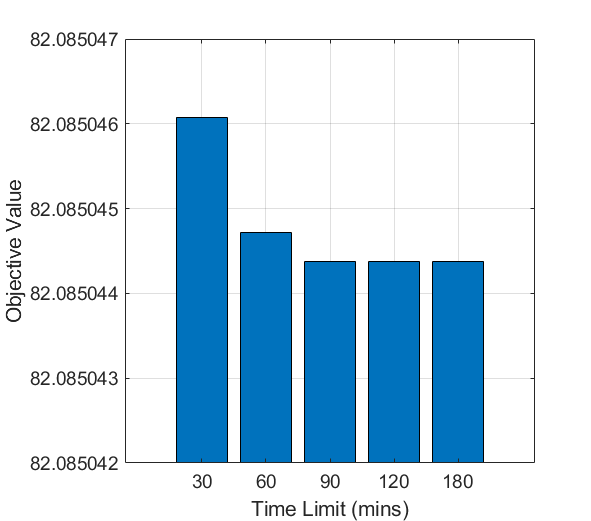
The simulation time limit: The SCIP solver is used with two parameters, the maximum number of threads used by the solver and the time limit to solve the model. In these experiments, the maximum number of threads is set to threads in order to run multiple experiments at the same time. However, we noticed that SCIP only used a single thread at any given time while switching between these threads during the run (i.e. SCIP did not use all threads concurrently). The time limit, on the other hand, is set in order to obtain a sub-optimal solution from the model in a timely manner. Limiting the time is also considered by previous studies [7] to avoid the long time that the model could take to solve a problem with a high number of input parameters. Figure 1 compares the objective value obtained as a function of multiple values of the time limit. When the time limit is set to minutes, the model provided the highest objective value. As the time limit increases, the objective value starts to saturate. So in light of these results, the time limit is set to hours for all subsequent experiments and this same value is already used in the literature [7].
The implemented scenario: A simple network scenario is implemented in order to obtain and analyze the results from the proposed optimization model. A total of two slices are considered and each slice consists of three procedures. Slice one requires registration with AMF re-allocation, handover, and authentication procedures. However, slice two requires general registration, handover, and authentication procedures. These procedures are described in the next section. The number of procedures sourced externally and the maximum VNF traffic are varied across the conducted experiments. Table III summarizes the network configuration of the studied scenario.
| Number of slices | Two |
| Procedures for Slice# | 1) Registration with AMF re-allocation procedure |
| 2) Handover procedure | |
| 3) Authentication procedure | |
| Procedures for Slice# | 1) General registration procedure |
| 2) Handover procedure | |
| 3) Authentication procedure | |
| Number of external procedures | Variable |
| Maximum VNF traffic capacity | Variable |
V The Implemented 5G Procedures
Although our model can support all existing 5G procedures defined by 3GPP in [23], only four procedures are implemented in this work to test the visibility and correctness of the model. These procedures are the general registration procedure, registration with AMF re-allocation procedure, handover procedure, and authentication procedure. In fact, implementing more procedures would enlarge the time needed to get results out of the model. In this section, those implemented procedures are described briefly and the sequence of their serving VNFs is provided. More details on these procedures can be found in 3GPP technical specification 23.502 [23].
General Registration Procedure: This procedure enables the UE to register with the 5G network to receive services. The UE can perform this procedure in different scenarios like the initial registration to join the network, the emergency registration to use the emergency services, etc. The sequence of VNFs used by this procedure is as follows: . Since the UE and the RAN are not actual VNFs but do appear in the sequence, we remove the UE and the RAN from the beginning of the procedures’ sequence while implementing the procedures in our model. More details on this limitation are explained in section VII.
Registration with AMF Re-Allocation Procedure: In this procedure, the initial AMF redirects the registration-related traffic to the target AMF. For instance, this can happen when the initial AMF cannot serve the UE, so a change in the AMF is required in this case. One important thing to mention here is that multiple types of AMFs can be seen in the sequence of VNFs, for instance, initial AMF, target AMF, etc. In our model, we consider these variants of AMFs as different VNFs to ensure that these VNFs are deployed separately from each other. The sequence of VNFs used by this procedure is as follows: .
Handover Procedure: Handover is another important procedure that takes place in cellular networks due to the mobility of the UEs. It can also be carried out due to other reasons like load balancing or achieving QoS requirements. Despite there being other more complex variants of the handover procedures specified by 3GPP in [23], however, we only consider the simple version of the handover in this work which is called ”Xn based inter NG-RAN handover without UPF re-allocation”. The sequence of VNFs used in this procedure is as follows: .
Authentication Procedure: 3GPP defines two protocols to be used for authentication procedure, Extensible Authentication Protocol-Authentication and Key Agreement (EAP-AKA’) and 5G-Authentication and Key Agreement (AKA). In this study, we only implement the EAP-AKA’. The selection of the authentication protocol is performed by Unified Data Management (UDM)/Authentication credential Repository and Processing Function (ARPF) depending on the Subscription Permanent Identifier (SUPI) of the UE [24]. The authentication procedure can be performed as part of other procedures such as the registration procedure or UE-triggered service request procedure. The sequence of VNFs serving this procedure is as follows: .
VI Results and Discussion
This section presents the results obtained from the proposed model. Various performance metrics are considered to test the correctness and effectiveness of the model including the impact of security constraints, the used capacities of the physical nodes, and the number of activated VNF instances. Additionally, the delay to complete the procedures based on the mapping of VNFs to the physical nodes is computed. The main goal of this analysis is to convey the benefits of the proposed security-aware optimization model along with the cost or overhead of prioritizing security. These results only apply to the parameters used and the environment tested. Hence, these results are not a general trend but show how the model could be used.
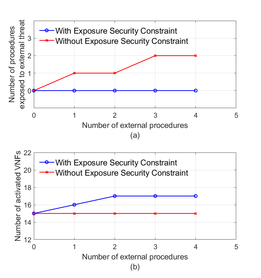
VI-A Impact of the Exposure Constraint
The impact of the exposure security constraint is analysed in terms of the security goals achieved and the additional overhead that occurred to the network operator. In this set of experiments, the VNF ’s maximum traffic constraint is disabled. Also, the number of external procedures is varied from (i.e. no procedure sourced externally) to (i.e. all procedures sourced externally) in steps of . We assume that any procedure originated by a UE or the RAN could be defined as a trusted or untrusted procedure. In this work, we consider a particular procedure is externally sourced if it is initiated by an untrusted UE or RAN. The Home Public Land Mobile Network (PLMN) (H-PLMN) (i.e., the operator) makes the final decision of whether a particular procedure is identified as trusted or untrusted based on, for example, the identities of the access network and/or visited network. Additionally, the home operator may consider a set of UEs or visited networks not sufficiently secure, however, the home operator policy may depend on reasons not related to security features of the connecting UE or RAN to categorize them into trusted or untrusted.
Figure 2(a) compares the effect of increasing the number of external procedures on the number of procedures exposed to external threats. Here, we check whether the first VNF of an external procedure is shared with other procedures. If it is shared, then the other procedures sharing the same VNF would be exposed to external threats as well. The assumption here is that the first VNF of the external procedure can be a target of attacks from a malicious UE or a rouge gNodeB (gNB) or other sources. As a consequence, the other procedures and slices served by that VNF would be exposed to the same external threats. As mentioned earlier in this paper, the exposure security constraint ensures that the first VNF of an external procedure is not shared with any other procedures and slices. As one can see from Fig. 2(a), with exposure constraint enabled, as the number of external procedures is increased, the number of procedures exposed to the threat remains at zero. However, with the exposure constraint disabled, more procedures sourced externally result in more procedures exposed to external threats as represented by the red curve. As seen in this figure, there is no increase in the number of procedures exposed to threats when the number of external procedures increases from to and from to as well. The reason behind this is that the first VNF of a procedure considered external is not being used by another procedure, which does not impact the results. Hence the results presented here depend greatly on the implemented scenario.
Figure 2(b) presents the cost of including security in the network in terms of the number of activated VNF instances. When there is no external procedure, the number of activated VNFs is the same with and without the security constraint. As the number of external procedures increases, the result without exposure constraint stays constant. However, with the exposure security constraint turned on, the number of activated VNFs would increase. This is because the constraint will ensure that the first VNF of the external procedure is not shared with any other procedure resulting in more VNF instances activated. More VNF activated will directly impact the required capacity which will increase the cost for the network operator. Similar to the previous result, with the exposure constraint, there is no increase in the number of activated VNFs when the procedures sourced externally are increased from to . This can be attributed to the fact that the model already activated separate VNFs for different procedures, hence, no new VNFs need to be initiated. Another reason could be that the first VNF of the external procedure is not used by another procedure which makes no change to the result.
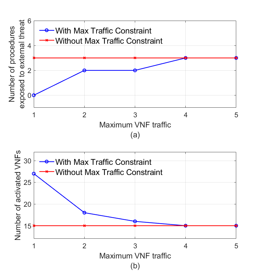
VI-B Impact of the Maximum VNF Traffic Constraint
To evaluate the impact of the maximum VNF traffic constraint, the exposure security constraint is disabled and only one procedure is assumed to be sourced externally. Figure 3(a) shows the benefit of using this constraint. In this set of experiments, the maximum allowed VNF traffic is ranging from to in steps of one. Also, each VNF is set to require one capacity unit to serve one procedure. The maximum VNF traffic simply means the number of procedures that the VNF can serve. Since one procedure is assumed as external, we consider a procedure exposed to the threat if it shares any VNF with the external procedure. Based on this assumption, without the maximum traffic constraint, the number of procedures exposed to external threats is constant at as shown in Fig. 3(a). With the VNF maximum traffic constraint enabled, the number of exposed procedures is zero initially. This is attributed to that each procedure is mapped to a unique VNF and there is no sharing. However, as the maximum limit of VNF traffic increases, the number of exposed procedures also increases until it becomes similar to the results without the maximum traffic constraint as shown in Fig. 3(a).
Figure 3(b) shows the cost of implementing this security constraint. The figure shows that when the maximum VNF traffic increases, the number of activated VNF instances stays constant at . However, with the maximum traffic constraint enabled, the number of initiated VNF instances is when the maximum VNF traffic is set to . This in turn requires more capacity and resources by the network operator. The total activated VNFs is reduced when the maximum VNF traffic limit is increased until it merges with the result of the other scenario (i.e. without the maximum traffic security constraint).
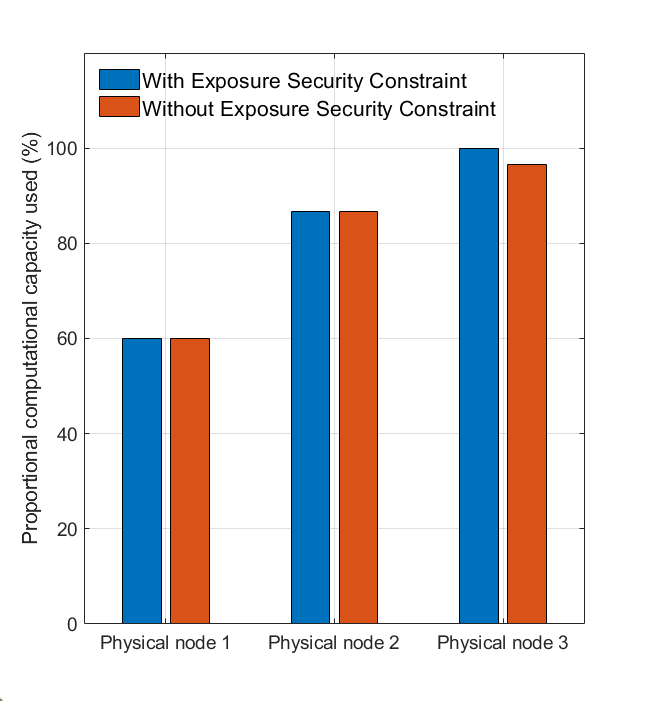
VI-C Physical Node Capacity
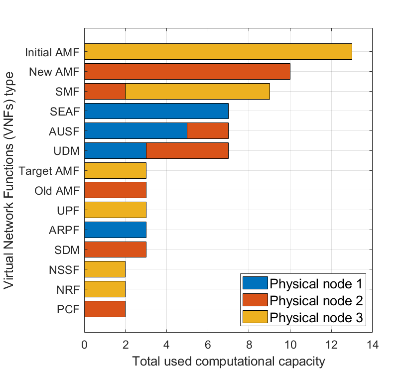
This subsection shows the amount of physical node capacity required to activate the VNFs that meet the slices requirements. For this set of experiments, the maximum VNF traffic limit is set to , and only the registration with AMF re-allocation procedure is set as an external procedure. Figure 4 shows the proportional computational capacity used for each physical node. In this experiment, the maximum VNF traffic constraint is enabled and the results are obtained with and without the exposure constraint. As shown in the figure, physical nodes and consume the same amount of capacity either with or without the security constraint. However, the capacity of physical node consumed is with the exposure constraint and about without the security constraint. The major takeaway from this figure is that the extra overhead of the security constraints is not huge if the network operators select moderate security requirements. To scrutinize this further, the total computational capacity of the physical nodes used by each VNF is reported in Fig. 5. It can be seen from the figure that the top three VNFs that use most of the capacity are the initial AMF, new AMF, and SMF. The initial AMF and new AMF are only deployed in physical nodes and , respectively. The SMF is mainly initialized in physical node but another instance of the SMF is also deployed in physical node . This observation also gives an indication of the VNFs which are mostly used by 5G procedures and hence making them critical to be protected from threats.
VI-D VNF Instance Capacity
In this subsection, we show the capacity used by VNF instances and their utilization. Figure 6 shows the proportional computational capacity used (excluding the base capacity) by each VNF instance out of its predefined maximum capacity. Here we only present the results of VNFs with more than one instance activated. Both security constraints are enabled in this experiment. It can be seen from the figure that three instances of the AMF are initiated. The AMF consumes the highest total capacity of the initialized instances among all VNFs. The SMF, UDM, and Authentication Server Function (AUSF) come next with two instances activated for each.
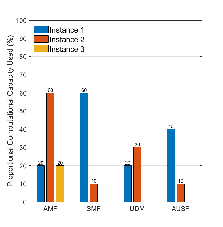
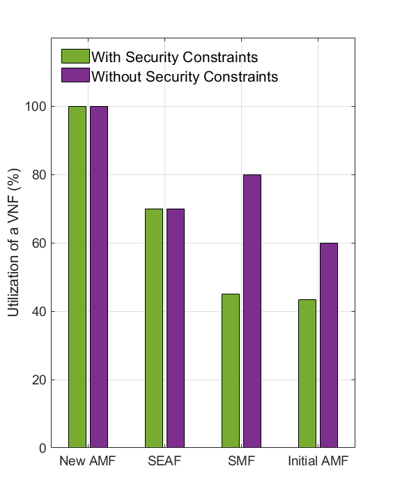
Figure 7 shows the utilization of VNFs with and without the security constraints. The utilization is computed by taking the average of the proportional capacity used across all instances of a particular VNF type. As shown in Fig. 7 the utilization of the new AMF, for example, is at . One important point to mention here is that the utilization of the SMF and initial AMF when the security constraints are enabled is lower than when they are disabled. The reason behind this is that the limit on the maximum VNF traffic and the exposure constraint results in more VNF instances activated, reducing the overall VNF utilization. However, this is a trade-off to make between protecting the network against threats and achieving higher utilization.
VI-E Procedure Delay
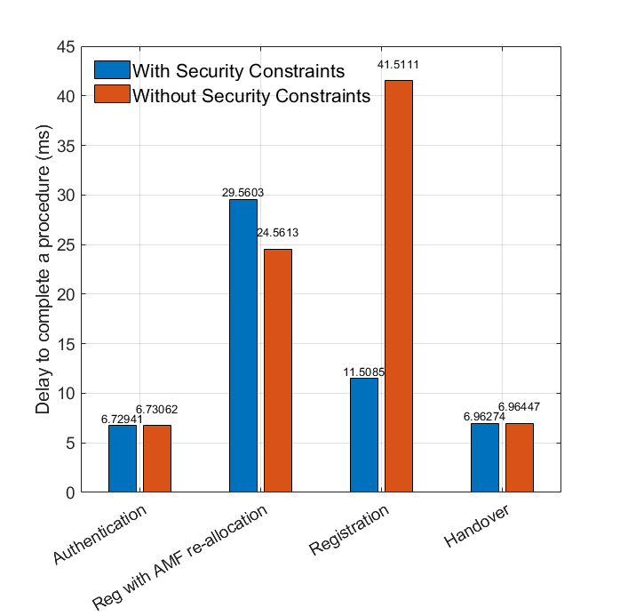
Lastly, we calculate the time it takes for each procedure to be completed. A delay average is reported if the same procedure is used across slices. The experiments are performed with both security constraints enabled and when they are disabled. As Fig. 8 shows, the delay to complete the authentication and handover procedures is around and it is almost the same for both scenarios (i.e. with and without the security constraints). The registration with the AMF re-allocation procedure takes more when the security constraints are enabled. However, the major difference in the delay is in the registration procedure. The delay to complete the procedure in the experiment without the security constraints is more than the delay in the experiment when the security constraints are enabled. This difference in the delay is because, for the results without the security constraints, some VNFs were arbitrarily deployed in different physical nodes resulting in extra propagation delay that contributes to the total delay. Another reason could be the limited run time for the model, which only provides a sub-optimal solution once the time limit is reached. Additionally, there is a trade-off between sharing VNFs and the delay as a lower number of VNFs does not always guarantee less delay due to multiple factors that can influence the delay.
VII Limitations
This section attempts to identify some limitations of the proposed model in this work and the way that it is planned to deal with them. These limitations are summarized in the following points:
-
•
UE and RAN assignments: The first limitation of the current implementation is considering the UE and the RAN as VNFs. Since UE and RAN are also part of 5G procedures explained in section V, the sequence of network entities that are involved during the procedure also includes the UE and the RAN. Currently, we do not distinguish between UE or RAN and other 5G VNFs in the implementation. In order to get around this issue, we remove the UE and the RAN from the beginning of the procedures’ sequence of VNFs. This is done to ensure that the exposure constraint does not consider the UE or the RAN as the first VNF of procedures set to be sourced externally. Therefore, removing the RAN or UE from the beginning of the sequence will guarantee that a 5G VNF will be the first VNF of this procedure. Another technique we employed is to assign zero base and processing capacities to the UE and the RAN. As a result, the model will map the UE and RAN to the physical nodes (similar to other VNFs) but their capacities will not be impacting the total capacity of the physical node. This is done to ensure the UE and the RAN contribute to the procedure delay without consuming the computational capacities of physical nodes.
-
•
Model time limit: Another limitation of the current model is that we limit the run time of the model to hours. This is done to obtain the results from the model in a timely manner. Once the time limit is reached, the model will provide the best solution obtained so far in terms of the objective function. Since there is a limit on the model run time, the results presented in this study might not be optimal.
VIII Conclusion
In this work, we propose an optimization-based security-aware VNF sharing model for 5G systems. The goal of the proposed model is not only to enable the efficient mapping of the VNFs to maximize their utilization but also to isolate slices by not sharing their critical VNFs to enhance security. For this, we introduce a systematic way to decide whether to share a particular VNF or not. To do so, two security constraints were defined in the proposed model; VNF ’s maximum traffic and VNF exposure constraints. The overall goal of the objective function is to minimize the computational capacity required and the total procedure delay. The numerical results of the model are obtained using the four standard 5G procedures with actual VNFs. The results show the advantage of using the security constraints in terms of securing the network slices, procedures, and VNFs by limiting the sharing of critical VNFs. The use of security constraints introduces additional costs to the network operators in the form of more capacity used. However, the use of security constraints will ensure the protection of critical network infrastructure from external threats such as, for example, DDoS attacks.
IX Acknowledgement
This work was supported by the Natural Sciences and Engineering Research Council of Canada (NSERC) and TELUS Communications through the Collaborative Research and Development (CRD).
References
- [1] W. Stallings, 5G Wireless: A Comprehensive Introduction. Addison Wesley, 2021.
- [2] NGMN, “Description of network slicing concept,” NGMN 5G P, vol. 1, no. 1, pp. 1–11, 2016.
- [3] X. Foukas, G. Patounas, A. Elmokashfi, and M. K. Marina, “Network slicing in 5g: Survey and challenges,” IEEE communications magazine, vol. 55, no. 5, pp. 94–100, 2017.
- [4] K. Samdanis, X. Costa-Perez, and V. Sciancalepore, “From network sharing to multi-tenancy: The 5G network slice broker,” IEEE Communications Magazine, vol. 54, no. 7, pp. 32–39, 2016.
- [5] 3rd Generation Partnership Project (3GPP), “System architecture for the 5G system 5GS,” Tech. Rep., TS. 23.501, Release 17, 2021.
- [6] I. Leyva-Pupo and C. Cervelló-Pastor, “Efficient solutions to the placement and chaining problem of User Plane Functions in 5G networks,” Journal of Network and Computer Applications, vol. 197, p. 103269, 2022. [Online]. Available: https://doi.org/10.1016/j.jnca.2021.103269
- [7] W. d. S. Coelho, A. Benhamiche, N. Perrot, and S. Secci, “Function splitting, isolation, and placement trade-offs in network slicing,” IEEE Transactions on Network and Service Management, vol. 4537, no. c, pp. 1–1, 2021.
- [8] W. Da Silva Coelho, A. Benhamiche, N. Perrot, and S. Secci, “On the impact of novel function mappings, sharing policies, and split settings in network slice design,” 16th International Conference on Network and Service Management, CNSM 2020, 2nd International Workshop on Analytics for Service and Application Management, AnServApp 2020 and 1st International Workshop on the Future Evolution of Internet Protocols, IPFutu, 2020.
- [9] F. Malandrino, C. F. Chiasserini, G. Einziger, and G. Scalosub, “Reducing service deployment cost through VNF sharing,” IEEE/ACM Transactions on Networking, vol. 27, no. 6, pp. 2363–2376, 2019.
- [10] H. Tang, D. Zhou, and D. Chen, “Dynamic Network Function Instance Scaling Based on Traffic Forecasting and VNF Placement in Operator Data Centers,” IEEE Transactions on Parallel and Distributed Systems, vol. 30, no. 3, pp. 530–543, 2019.
- [11] T. Truong-Huu, P. M. Mohan, and M. Gurusamy, “Service Chain Embedding for Diversified 5G Slices with Virtual Network Function Sharing,” IEEE Communications Letters, vol. 23, no. 5, pp. 826–829, 2019.
- [12] C. Mei, J. Liu, J. Li, L. Zhang, and M. Shao, “5G network slices embedding with sharable virtual network functions,” Journal of Communications and Networks, vol. 22, no. 5, pp. 415–427, 2020.
- [13] S. Agarwal, F. Malandrino, C. F. Chiasserini, and S. De, “Joint VNF Placement and CPU Allocation in 5G,” Proceedings - IEEE INFOCOM, vol. 2018-April, pp. 1943–1951, 2018.
- [14] M. Golkarifard, C. F. Chiasserini, F. Malandrino, and A. Movaghar, “Dynamic VNF placement, resource allocation and traffic routing in 5G,” Computer Networks, vol. 188, no. January, p. 107830, 2021. [Online]. Available: https://doi.org/10.1016/j.comnet.2021.107830
- [15] M. C. Luizelli, W. L. da Costa Cordeiro, L. S. Buriol, and L. P. Gaspary, “A fix-and-optimize approach for efficient and large scale virtual network function placement and chaining,” Computer Communications, vol. 102, pp. 67–77, 2017.
- [16] D. Sattar and A. Matrawy, “Optimal Slice Allocation in 5G Core Networks,” IEEE Networking Letters, vol. 1, no. 2, pp. 48–51, 2019.
- [17] D. SATTAR and A. MATRAWY, “Towards secure slicing: Using slice isolation to mitigate DDoS attacks on 5G core network slices,” 2019 IEEE Conference on Communications and Network Security (CNS), pp. 82–90, 2019.
- [18] ITU-T, “Y.3101: Requirements of the IMT-2020 network,” 2018. [Online]. Available: http://www.itu.int/rec/T-REC-Y.3101-201801-I/en
- [19] I. Dunning, J. Huchette, and M. Lubin, “Jump: A modeling language for mathematical optimization,” SIAM Review, vol. 59, no. 2, pp. 295–320, 2017.
- [20] J. Bezanson, A. Edelman, S. Karpinski, and V. B. Shah, “Julia: A fresh approach to numerical computing,” SIAM review, vol. 59, no. 1, pp. 65–98, 2017. [Online]. Available: https://doi.org/10.1137/141000671
- [21] “Scip.” [Online]. Available: https://www.scipopt.org/
- [22] Scipopt, “Scipopt/scip.jl: Julia interface to scip solver.” [Online]. Available: https://github.com/scipopt/SCIP.jl
- [23] 3rd Generation Partnership Project, “Group services and system aspects;procedures for the 5G system 5GS; stage 2,” TS 23.502, Release 17, 2021.
- [24] 3rd Generation Partnership Project 3GPP, “Security architecture and procedures for 5G system,” Tech. Rep., TS 33.501, Release 17, 2021.