Majorana bound state parity exchanges in planar Josephson junctions
Abstract
We describe a scheme to exchange fermion parity between two pairs of Majorana bound states mediated by coupling with a centralized quantum dot. We specifically formulate such a scheme for Majorana bound states nucleated in the Josephson vortices formed in a four-fold crossroads junction of planar topological superconductors in the presence of a perpendicular magnetic field. This platform yields several advantages to the execution of our scheme as compared to similar ideas proposed in wire geometries, including control over the positions of the MBS and hence, a tunable coupling with the quantum dot. We show that moving the MBS along the junctions through voltage pulses can facilitate parity exchange via a two-step process, with intermediate projective measurements of the quantum dot charge. Thus, we formulate a way to achieve single qubit operations for MBS in extended Josephson junctions through projective measurements of quantum dot charge. We also discuss the physical viability of our scheme with a particular focus on changes in quantum dot energy levels as a measurable indicator of the success of the scheme.
The heightened pursuit for material platforms to host robust qubits and scalable schemes for achieving error-resistant quantum computing has elicited a surge of experimental and theoretical advances in contemporary condensed matter physics. In the realm of topologically protected qubits, Majorana bound states (MBS) in various topological superconducting setups continue offering promise as front-runners [1]. The original nanowire geometries, while facing setbacks, laid down the foundations for integrating the fields of condensed matter, material physics and quantum information science in designing viable platforms, and computational schemes [2, 3, 4, 5, 6, 7, 8]. In recent times, extended junctions have become popular platforms to host MBS even at low magnetic field strengths [9, 10, 11, 12, 13]. Early proposals involve proximity-induced superconductivity on the surface of topological insulators in 2D and 3D with an externally applied magnetic field resulting in spatially separated MBS nucleating in Josephson vortices [9, 10, 14, 2, 15, 16, 17, 18, 19, 20, 21, 13].
While the manipulation of MBS cannot achieve a universal set of topologically protected quantum gates, the primary step in all these efforts is to construct effective gate operations by braiding the Majorana, and then produce reliable readout mechanisms for the same. Schemes for performing gate operations involve two approaches: braiding via the physical motion of MBS and measurement-based braiding over stationary MBS [22, 23]. While these schemes and protocols have been thoroughly explored in the nanowire context, in order to ensure progress, it is imperative that these schemes be innovatively adapted to a range of MBS settings [24, 25, 26, 27].
Here we propose a scheme for MBS braiding and related fermion parity qubit operations that cater to the challenges and virtues of extended topological Josephson junction geometries. The scheme involves shuttling multiple MBS along such junctions towards a quantum dot that forms a parity measurement apparatus, thus forming a hybrid between the two gate operation approaches [28, 29, 29, 30, 31]. In what follows, we first outline the scheme. We next detail the physics of Josephson junction vortices as a natural pathway for nucleating MBS and efficiently manipulating them via the application of magnetic field pulses and local currents. We then discuss the workings of the quantum dot as relevant to our scheme. Finally, we bring these components together to present the specific manipulations and measurements that together form a controlled scheme for parity qubit operations.
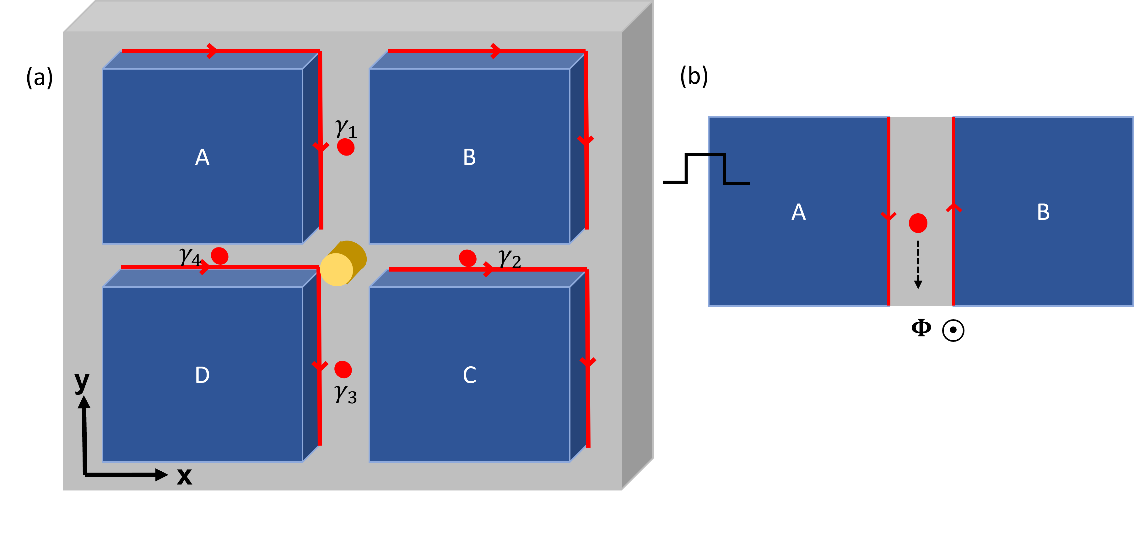
Outline of Scheme: The MBS-based scheme forming the core of this work is as follows. Our geometry consists of a four-point crossroads formed by four extended junctions between superconducting islands as shown in Fig. 1. Each of the four junctions has sufficient magnetic flux to nucleate at least one Majorana bound state (MBS). The center of the crossroads has a quantum dot that can be coupled to each of these 4 MBS. The extended junctions provide smooth channels for shuttling MBS via application of local voltage/current pulses across the bordering superconductors. The proximity of each MBS to the central dot controls the tunnel coupling between them. Coulomb blockade physics within the dot serves to dictate transfer of electrons between pairs of MBS and the dot as well as to act as a readout.
For a pair of MBS and , as commonly done, we can define the complex fermion operator [32]. The occupation number of this non-local electronic state has two eigenvalues (0 and 1) and defines the parity of that pair of MBS. Since we have 4 MBS in our system, the corresponding Hilbert space is 4-dimensional, and the 3 possible ways of choosing the pairs of complex fermions correspond to different basis choices for the Hilbert space. In this work, parity exchanges take place between pairs of MBS mediated by the quantum dot, which is tuned to a regime of operation where it is treated as a two-level system that can be occupied or unoccupied.
Our scheme consists of two stages. In the initial stage, a pair of MBS with parity 1 (say and ) are coupled to the quantum dot, with the interaction resulting in transferring the excess charge to the initially unoccupied quantum dot. In the second stage, a different pair of MBS (that is, at least one of the two MBS is different from and ) are coupled to the quantum dot, with this interaction resulting in changing their non-local parity to 1. As a specific example, we consider two canonical charge transfers - (a) Parity transfer from to and (b) Parity transfer from to [33, 34]. All other combinations can be considered as trivial variations or combinations of these two transformations. Observation of such parity exchanges would correspond to landmark demonstrations of parity qubit manipulation and non-Abelian rotations in the degenerate qubit subspace.
MBS in the extended junctions: We model the extended junction geometry of Fig. 1 in the framework of the Bogoliubov-de Gennes (BdG) Hamiltonian for a spinless two-dimensional topological superconductor [35, 21, 36], given by
| (1) |
It is useful to represent the chiral pairing operator in the form , where denotes the superconducting phase.
To first focus on a single extended junction, say, between islands and , each island has a low-energy chiral Majorana state that runs along the boundaries of the superconductor (indicated in red in Fig. 1). The Josephson coupling between islands can be described by an effective Hamiltonian obtained by projecting onto the space spanned by their respective chiral dispersive Majorana edge modes [9, 17]. This effective Hamiltonian is given by
| (2) |
Here and are chiral Majorana fermions on the boundaries of island and , and is the Josephson coupling term between the chiral Majoranas in the junction region , of length [21, 36]. The superconducting phase difference between the islands is given by and the variable is the coordinate along the boundaries of the islands. A small magnetic flux is now applied in the junction region. Since the Josephson coupling is only present in the region , we will use the coordinate for junction to focus on this region.
In the short junction limit [37] (when the length of the junction is shorter than the Josephson coherence length, or equivalently the Josephson current density is much lesser than for junctions of width ), the gauge-invariant superconducting phase difference is defined up to a constant . In general this constant could be determined by external phase bias (voltage/current/flux in a solenoid) between the two superconductors. A Josephson vortex trapping a MBS is obtained in the junction whenever is an odd multiple of [9, 10, 17, 21, 36]. Therefore, the number of MBS in each junction is given by the integer part of the amount of flux quanta in that junction. Further, in this limit, the Josephson vortex solution takes the form of a large soliton [38]. In the background of such soliton states, the zero energy eigenstates of Eq. (2) are real vectors of the form corresponding to the MBS. Here, the functions and are of the form and , the specific constants being determined by boundary conditions and external flux quanta (if any) penetrating the islands.
In the presence of a DC voltage applied across two islands [10, 36] (say and ) for a time , the form of the phase difference across the junction is modified by the AC Josephson effect to include an additional term of . This form for the phase difference across the junction gives rise to mobile solitonic Majorana states , where and . The velocity of the MBS is thus . The time dependent nature of the problem affects the eigenstates of Eq. (2) in that the zero energy states now have a modified “boosted” mass factor . Additionally (and crucially), we see that the application of voltage bias across the junction results in the traversal of the MBS along the junction. For a magnetic field pointing upwards from the plane of the islands, and positive voltage bias , this setup corresponds to the vortices in the junction moving in the direction. This is schematically indicated in Fig. 1(b). The reversal of any of these features - direction of magnetic field, sign of the pulse, or application of the pulse on instead of - would result in the MBS moving in the opposite direction. It must be noted here that the magnitude of the voltage pulse determines the velocity of the MBS. However, very high voltages can result in the destruction of the MBS through quasiparticle poisoning or hybridization effects. Therefore, it is necessary to pick appropriate voltages that ensure adiabatic transport of the MBS in the Josephson vortex cores to maintain the topologically nontrivial ground state of the system.
In the four junction setup, we assume all four islands to be initially be at the same external voltage/common ground. Thus, applying a voltage on island A affects both as well as This voltage pulse results in the MBS in the AB junction moving in the direction and those in the AD junction moving in the direction. We use the convention described here in our scheme to exchange non-local MBS fermion parity. In each case considered, we start with total fermion parity being odd , with all four MBS being uncoupled to the dot. The dot itself is in the unoccupied state.
MBS-Quantum dot interaction: We now turn to the physics of the central quantum dot at the intersection of the four extended junctions and its coupling to the MBS. The quantum dot has an associated single-particle energy level spacing and a charging energy. Considering a small quantum dot with large level spacing, it is enough to account for only the level nearest to the Fermi energy. In this case, the dot can be described by the single-level Hamiltonian
| (3) |
where is the occupation of the quantum dot, is the constant ground state energy and sets the charging energy, tunable by the gate voltage. We assume here that the mesoscopic superconducting island is large enough to neglect its charging energy.
The total Hamiltonian of the entire system is thus given by
| (4) |
where the last term describes single-electron tunneling between the quantum dot and the four MBS closest to it. It is specified most generally as
| (5) |
The four coupling constants are in general complex, and are exponentially suppressed with increasing distance between the MBS and the quantum dot. Thus, the couplings can be tuned by moving the MBS relative to the quantum dot, as described above.
As a simple first step, we explore the interaction between a pair of Majorana bound states and a quantum dot to show the oscillation and hence exchange of parity between the two. In the complex fermion notation , the relevant part of the tunneling Hamiltonian in Eq. (5) takes the form
| (6) |
where , and the redefined complex coupling constants and . This Hamiltonian acts on the Hilbert space spanned by , where the first ket subscript refers to electronic states with the specified occupation numbers formed by the Majorana degrees of freedom and the second ket with subscript refers to those of the dot. In general, this Hamiltonian can have time-dependent coupling parameters, especially as MBS are being moved. We will specifically consider the case where they are brought close to the dot and held there. It is clear that this Hamiltonian conserves the total parity of the system. Therefore, without loss of generality, let us consider the temporal dynamics of the odd parity state . The time-evolution of the state is governed by the amplitude and takes the form
| (7) |
where . If the state is allowed to evolve up to time , the state is fully transformed to . Further evolution of the quantum state can be arrested by turning off the coupling constant through moving the MBS away from the quantum dot. Thus, we obtain a time scale for full parity transfer between the Majorana states and the quantum dot. However in practice, turning off the coupling at precise instants of time may be challenging, requiring high precision control over the MBS. The accumulated phases can also affect the desired outcome in the scheme, making the transformation not topologically protected. We therefore now turn to projective measurements[23, 39] to exchange parity between the quantum dot and the MBS pair.
A weak tunnel-coupling in Eq. (6) can be used to perform a (weak) measurement of the Majorana parity [40]. In order to illustrate this, we now turn to the perturbative effect of the tunneling in Eq. (6) to the quantum dot Hamiltonian in Eq. (3). We evaluate the parity-dependent shift on the energy levels of the quantum dot. We label the ground and excited states of the quantum dot as and .
The modified energy levels due to the perturbation take the form
| (8) | ||||
| (9) |
where and is the initial parity of the MBS. It is notable then, that the parity dependent shift in energy levels scales as , and thus, is only measurable when the even and odd sector couplings have different magnitudes [40, 41]. On moving the MBS away from the dot, the perturbative shift vanishes. Since the quantum dot measures MBS parity in a non-destructive way involving no hybridization, the measurement may be performed multiple times by repeating the cycle of turning on interaction by moving the MBS pair close to the dot and measurement of the charge, and then undoing the measurement if the desired outcome is not obtained by making a different pair interact with the dot. Over many such cycles, the desired outcome of complete parity exchange between the dot and the MBS pair occurs. We utilize these concepts in our key proposed scheme, where parity exchanges between pairs of MBS are mediated by the quantum dot.
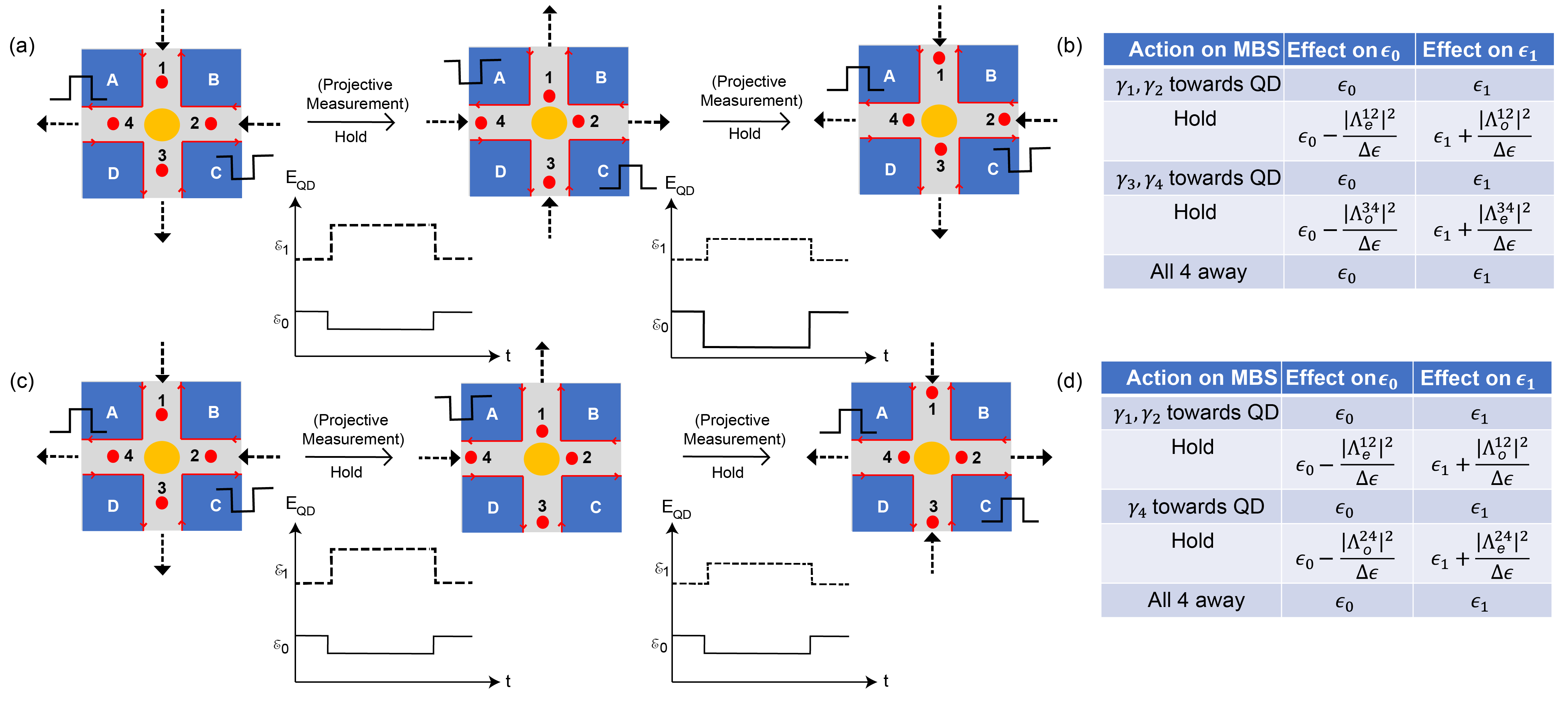
Qubit manipulation: To illustrate our key scheme, we can break up the steps corresponding to the transfer from to in the following way: (i) and are moved close to the quantum dot, initialized to state , and interact with it. The dot-MBS system is now in the superposition , and a projective measurement of the dot is carried out to obtain the state . (ii) The Majoranas and are moved away so that and can now move close to the quantum dot and interact with it. The dot-MBS system is now in the superposition , and a projective measurement is carried out to obtain the state , which is the desired final state. The voltage pulse sequence and corresponding changes in QD energy levels are indicated in Fig. 2.
A similar break up can be laid out for the transfer from to : (i) and are moved close to the quantum dot, initialized to state and interact with it. The dot-MBS system is now in the superposition , and a projective measurement of the dot is carried out to obtain the state . (ii) is moved away and is brought close to the quantum dot and interacts with it. The dot-MBS system is now in the superposition , and a projective measurement is carried out to obtain the state , which is the desired final state. The voltage pulse sequence and corresponding changes in QD energy levels are indicated in Fig. 2.
These schemes are ways of performing net rotations over the degenerate subspace spanned by the states , with the first two states spanning the odd parity sector and the latter two spanning the even sector. Operations over this subspace may be represented in terms of the unitary operators [34]. The action of corresponds to exchanging the MBS and . The first transformation would then be equivalent to the action of the unitary on the input state. Similarly, the second transformation is equivalent to the action of the unitary on the input state.
We now take a closer look at parity transfer between the MBS and the quantum dot using projective measurements. Since the planar junction offers precise control over the coupling interaction through MBS motion, this scheme is better conceived in our geometry than in wire junctions where the MBS are stationary. One can draw an analogy with the Stern-Gerlach experiment to understand the idea of projective measurements.
When the quantum dot interacts with a pair of MBS (say and ), the quantum state exists in an entangled superposition of states with the same parity as shown in Eq. (7). Our goal here, then, is to use the quantum dot to measure the non-local parity of the MBS pair, and in performing the measurement, effectively transfer parity from the MBS to the quantum dot [41]. It is useful to map the MBS parity operators to spin operators in the following way:
| (10) |
We can then rewrite the state in Eq. (7) with arbitrary coefficients in terms of eigenstates of the operator-
| (11) |
The desired outcome on measuring the quantum dot is the state . If it is not obtained on measuring the dot, we undo the measurement by moving close to the dot and away from the dot by applying a positive voltage pulse on superconducting island and performing a charge measurement, which is equivalent to measuring the operator . We can then revert to measuring by applying a negative voltage pulse on island . The probability of obtaining for the first time on the -th such cycle is . The total probability of obtaining is thus
| (12) |
That is, after enough cycles, one is guaranteed to obtain the desired outcome. Thus, in each of the two schemes, replacing the hold times to projective measurements makes them less dependant on needing precise and time sensitive control for the scheme to work.
Such measurements are performed over the crucial intermediate step involving the Rabi oscillation state given in Eq. (7). Were there infinitely precise control, one could move away the MBS precisely at time , smoothly changing the changing the state from to , and preventing any further time evolution or phase accumulation. However, in practice, the states accumulate various arbitrary dynamical phases over time evolution and interaction with the quantum dot, as seen in Eq. (7). Consider the second transformation for instance. Most generally, it can be written as with and [34, 42]. This would render these steps non topological, thus necessitating projective measurement in order to design protected gate operations. However, the possibility to accumulate such phases on specific qubit states will be useful in such geometries in designing a phase gate. Though not topologically protected, this will enable us in creating a universal set of quantum gates that can be realized on the extended junction platform.
Outlook: Turning to the experimental feasibility of our proposal, several components have been separately investigated and established. Josephson junction phase slips in extended geometries and response to fields and voltage pulses have a venerable history in a variety of superconductors. Applications of quantum dot physics in quantum information science is a vast area of study [43, 44, 45, 46, 47, 48, 49]. More recently, extended topological junctions are receiving a concerted push with promising initial indicators of MBS physics [19, 20, 50, 51, 52, 53, 54, 55].
The realization of our proposal would require a synergy of these disparate experimental elements working hand-in-hand with more involved theoretical treatments. In an ideal world, the two MBS manipulation schemes together, while lacking complete topological protection, could even have the required elements for universal quantum computation. In reality, even a single step, such as experimentally demonstrating adiabatic motion of vortices and associated MBS via STM measurements or coupling of MBS and the quantum dot via energy shifts and Rabi oscillation, would constitute a milestone.
Acknowledgements: We are grateful to detailed discussions with Dale Van Harlingen, Guang Yue, Jessica Montone, Nick Abboud. We acknowledge the support of the National Science Foundation through Grant No. DMR-2004825 (VS and SV), Grant No. PHY-1748958 (VS), and the Quantum Leap Challenge Institute for Hybrid Quantum Architectures and Networks Grant No. OMA-2016136 (SV, AL). This material is based upon work supported by the Office of the Under Secretary of Defense for Research and Engineering under award No. FA9550-22-1-0354 (JIV).
References
- Sarma et al. [2015] S. D. Sarma, M. Freedman, and C. Nayak, npj Quantum Information 1, 15001 (2015).
- Lutchyn et al. [2010] R. M. Lutchyn, J. D. Sau, and S. Das Sarma, Phys. Rev. Lett. 105, 077001 (2010).
- Oreg et al. [2010] Y. Oreg, G. Refael, and F. von Oppen, Phys. Rev. Lett. 105, 177002 (2010).
- Alicea [2012] J. Alicea, Reports on Progress in Physics 75, 076501 (2012).
- Aguado [2017] R. Aguado, Nuovo Cimento Rivista Serie 40, 523 (2017), arXiv:1711.00011 [cond-mat.supr-con] .
- Sestoft et al. [2018] J. E. Sestoft, T. Kanne, A. N. Gejl, M. von Soosten, J. S. Yodh, D. Sherman, B. Tarasinski, M. Wimmer, E. Johnson, M. Deng, J. Nygård, T. S. Jespersen, C. M. Marcus, and P. Krogstrup, Phys. Rev. Mater. 2, 044202 (2018).
- Zhang et al. [2019] H. Zhang, D. E. Liu, M. Wimmer, and L. P. Kouwenhoven, Nature Communications 10, 5128 (2019), arXiv:1905.07882 [cond-mat.mes-hall] .
- Chen et al. [2021] J. Chen, M. Gomanko, G. Badawy, E. Bakkers, K. Zuo, V. Mourik, and S. Frolov, Nature Physics 17, 482 (2021).
- Fu and Kane [2008] L. Fu and C. L. Kane, Phys. Rev. Lett. 100, 096407 (2008).
- Potter and Fu [2013] A. C. Potter and L. Fu, Phys. Rev. B 88, 121109 (2013).
- Williams et al. [2012] J. R. Williams, A. J. Bestwick, P. Gallagher, S. S. Hong, Y. Cui, A. S. Bleich, J. G. Analytis, I. R. Fisher, and D. Goldhaber-Gordon, Phys. Rev. Lett. 109, 056803 (2012).
- Ye et al. [2019] X. Ye, J. Cook, E. D. Huemiller, A. D. K. Finck, P. Ghaemi, T. Vojta, V. P. Adiga, S. R. Saha, J. Paglione, and C. Kurter, Phys. Rev. B 100, 104505 (2019).
- Flensberg et al. [2021] K. Flensberg, F. von Oppen, and A. Stern, Nature Reviews Materials (2021), 10.1038/s41578-021-00336-6.
- Fu and Kane [2009] L. Fu and C. L. Kane, Phys. Rev. B 79, 161408 (2009).
- Stern and Berg [2019] A. Stern and E. Berg, Phys. Rev. Lett. 122, 107701 (2019).
- Dolcini et al. [2015] F. Dolcini, M. Houzet, and J. S. Meyer, Phys. Rev. B 92, 035428 (2015), arXiv:1503.01949 [cond-mat.mes-hall] .
- Grosfeld and Stern [2011] E. Grosfeld and A. Stern, Proceedings of the National Academy of Sciences 108, 11810 (2011), https://www.pnas.org/content/108/29/11810.full.pdf .
- Pientka et al. [2017] F. Pientka, A. Keselman, E. Berg, A. Yacoby, A. Stern, and B. I. Halperin, Phys. Rev. X 7, 021032 (2017).
- Fornieri et al. [2019] A. Fornieri, A. M. Whiticar, F. Setiawan, E. Portolés, A. C. C. Drachmann, A. Keselman, S. Gronin, C. Thomas, T. Wang, R. Kallaher, G. C. Gardner, E. Berg, M. J. Manfra, A. Stern, C. M. Marcus, and F. Nichele, Nature 569, 89 (2019).
- Ren et al. [2019] H. Ren, F. Pientka, S. Hart, A. T. Pierce, M. Kosowsky, L. Lunczer, R. Schlereth, B. Scharf, E. M. Hankiewicz, L. W. Molenkamp, B. I. Halperin, and A. Yacoby, Nature 569, 93 (2019).
- Hegde et al. [2020] S. S. Hegde, G. Yue, Y. Wang, E. Huemiller, D. Van Harlingen, and S. Vishveshwara, Annals of Physics 423, 168326 (2020).
- Alicea et al. [2011] J. Alicea, Y. Oreg, G. Refael, F. von Oppen, and M. P. A. Fisher, Nature Physics 7, 412 (2011).
- Bonderson et al. [2008] P. Bonderson, M. Freedman, and C. Nayak, Phys. Rev. Lett. 101, 010501 (2008), arXiv:0802.0279 .
- Zhou et al. [2022] T. Zhou, M. C. Dartiailh, K. Sardashti, J. E. Han, A. Matos-Abiague, J. Shabani, and I. Žutić, Nat. Commun. 13, 1738 (2022).
- Fatin et al. [2016] G. L. Fatin, A. Matos-Abiague, B. Scharf, and I. Žutić, Phys. Rev. Lett. 117, 077002 (2016).
- Nothhelfer et al. [2022] J. Nothhelfer, S. A. Díaz, S. Kessler, T. Meng, M. Rizzi, K. M. D. Hals, and K. Everschor-Sitte, Phys. Rev. B 105, 224509 (2022).
- Konakanchi et al. [2022] S. T. Konakanchi, J. I. Väyrynen, Y. P. Chen, P. Upadhyaya, and L. P. Rokhinson, (2022), arXiv:2210.10650 [cond-mat.mes-hall] .
- Lupo et al. [2022] E. Lupo, E. Grosfeld, and E. Ginossar, PRX Quantum 3, 020340 (2022).
- Yavilberg et al. [2015] K. Yavilberg, E. Ginossar, and E. Grosfeld, Phys. Rev. B 92, 075143 (2015).
- Li et al. [2018] T. Li, W. A. Coish, M. Hell, K. Flensberg, and M. Leijnse, Phys. Rev. B 98, 205403 (2018).
- Väyrynen et al. [2021] J. I. Väyrynen, D. I. Pikulin, and R. M. Lutchyn, Phys. Rev. B 103, 205427 (2021).
- Kitaev [2003] A. Kitaev, Annals of Physics 303, 2 (2003).
- Nayak et al. [2008] C. Nayak, S. H. Simon, A. Stern, M. Freedman, and S. Das Sarma, Rev. Mod. Phys. 80, 1083 (2008).
- Ivanov [2001] D. A. Ivanov, Phys. Rev. Lett. 86, 268 (2001).
- Stone and Roy [2004] M. Stone and R. Roy, Phys. Rev. B 69, 184511 (2004).
- Abboud et al. [2022] N. Abboud, V. Subramanyan, X.-Q. Sun, G. Yue, D. Van Harlingen, and S. Vishveshwara, Phys. Rev. B 105, 214521 (2022).
- Tinkham [2004] M. Tinkham, Introduction to Superconductivity (Dover Publications, 2004).
- Grosfeld et al. [2011] E. Grosfeld, B. Seradjeh, and S. Vishveshwara, Phys. Rev. B 83, 104513 (2011).
- Karzig et al. [2019] T. Karzig, Y. Oreg, G. Refael, and M. H. Freedman, Phys. Rev. B 99, 144521 (2019).
- Karzig et al. [2017] T. Karzig, C. Knapp, R. M. Lutchyn, P. Bonderson, M. B. Hastings, C. Nayak, J. Alicea, K. Flensberg, S. Plugge, Y. Oreg, C. M. Marcus, and M. H. Freedman, Phys. Rev. B 95, 235305 (2017).
- Steiner and von Oppen [2020] J. F. Steiner and F. von Oppen, Phys. Rev. Res. 2, 033255 (2020).
- Choi and Sim [2019] S.-J. Choi and H. S. Sim, “Josephson junction of finite-size superconductors on a topological insulator under a magnetic field,” (2019), arXiv:1908.11403 [cond-mat.mes-hall] .
- Liu and Baranger [2011] D. E. Liu and H. U. Baranger, Phys. Rev. B 84, 201308 (2011).
- Gong et al. [2023] T. Gong, X.-F. Dai, S.-F. Zhang, and W.-J. Gong, Physica E: Low-dimensional Systems and Nanostructures 145, 115475 (2023).
- Chen et al. [2014] Q. Chen, K.-Q. Chen, and H.-K. Zhao, Journal of Physics: Condensed Matter 26, 315011 (2014).
- Dvir et al. [2023] T. Dvir, G. Wang, N. van Loo, C.-X. Liu, G. P. Mazur, A. Bordin, S. L. D. ten Haaf, J.-Y. Wang, D. van Driel, F. Zatelli, X. Li, F. K. Malinowski, S. Gazibegovic, G. Badawy, E. P. A. M. Bakkers, M. Wimmer, and L. P. Kouwenhoven, Nature 614, 445 (2023).
- Liu et al. [2022] C.-X. Liu, H. Pan, F. Setiawan, M. Wimmer, and J. D. Sau, “Fusion protocol for majorana modes in coupled quantum dots,” (2022).
- Zhang and Sun [2022] H.-R. Zhang and Y.-P. Sun, Frontiers in Physics 10 (2022), 10.3389/fphy.2022.985198.
- Leijnse and Flensberg [2011] M. Leijnse and K. Flensberg, Phys. Rev. B 84, 140501 (2011).
- Lesser et al. [2021] O. Lesser, A. Saydjari, M. Wesson, A. Yacoby, and Y. Oreg, Proceedings of the National Academy of Sciences 118, e2107377118 (2021), https://www.pnas.org/doi/pdf/10.1073/pnas.2107377118 .
- Mohanta et al. [2021] N. Mohanta, S. Okamoto, and E. Dagotto, Communications Physics 4, 163 (2021).
- Liu et al. [2018] D. T. Liu, J. Shabani, and A. Mitra, Phys. Rev. B 97, 235114 (2018).
- Maistrenko et al. [2021] O. Maistrenko, B. Scharf, D. Manske, and E. M. Hankiewicz, Phys. Rev. B 103, 054508 (2021).
- Liu et al. [2019] D. T. Liu, J. Shabani, and A. Mitra, Phys. Rev. B 99, 094303 (2019).
- Melo et al. [2019] A. Melo, S. Rubbert, and A. R. Akhmerov, SciPost Phys. 7, 039 (2019).