Fluxonium Qubits in a Flip-Chip Package
Abstract
The strong anharmonicity and high coherence times inherent to fluxonium superconducting circuits are beneficial for quantum information processing. In addition to requiring high-quality physical qubits, a quantum processor needs to be assembled in a manner that minimizes crosstalk and decoherence. In this paper, we report work on fluxonium qubits packaged in a flip-chip architecture, where a classical control and readout chip is bump-bonded to the quantum chip, forming a multi-chip module (MCM). The modular approach allows for improved connectivity between the qubits and control/readout elements, and separate fabrication processes. We characterize the coherence properties of the individual fluxonium qubits, demonstrate high fidelity single-qubit gates with 6 ns microwave pulses (without DRAG), and identify the main decoherence mechanisms to improve on the reported results.
I Introduction
Superconducting circuits are one of the leading quantum computing platforms due to the orders-of-magnitude growth in coherence times [1, 2] and a path to scalability derived from existing CMOS technologies [3]. To date, superconducting quantum processors composed of many tens of qubits have been demonstrated [4, 5]. A fault-tolerant quantum computer capable of solving classically intractable problems would require millions of physical qubits [6]. This number can be lowered by improving the qubit performance. Nevertheless, the need for scaling up remains.
A major obstacle to scaling is the overhead related to routing the multitude of lines for qubit control and readout in a planar architecture. The main challenges arise from signal crosstalk between qubits and the conflicting requirement of coupling high-Q qubits to lossier control and readout circuitry. Additionally, we expect that new qubit control methods will be necessary to realize large-scale quantum processors, since the power consumption and physical overhead of conventional analog microwave control is daunting. One example is single flux quantum (SFQ) technology, where the qubits are controlled using digital voltage pulses [7, 8], which would greatly reduce the level of instrumentation overhead.
A way to scale up from the planar level is to utilize multiple circuit layers; separating the quantum and classical circuitry [9, 10, 11]. One approach is the flip-chip package, where a carrier chip responsible for qubit control and readout is bump-bonded to the quantum chip (flip-chip), which is flipped such that it faces the carrier. The two chips are separated by vacuum or a chip interposer, and the qubit control lines and readout resonators couple capacitively or inductively to the qubit.
The modular approach allows classical and quantum elements to be fabricated separately, thereby protecting the qubits from unnecessary exposure to additional fabrication processes. It also improves device yield, since defective qubits do not affect the functionality of the carrier chip, and vice versa. Furthermore, instead of routing signals from the perimeter of the chip, interconnects can be made through its plane, reducing the overlap between individual circuit elements [12]. The flip-chip package is also optimal for digital qubit control using SFQ pulses because the quasiparticles [13, 14] generated on the active carrier chip by the SFQ circuits are isolated from the quantum chip [15]. To date, flip-chip packaging has been explored on transmon [16] and capacitively-shunted flux [17, 18] qubits, demonstrating that the qubit performance is not limited by this architecture [19, 20, 21, 22, 23].
Over the past decade, the fluxonium circuit [24] has emerged as a promising platform for superconducting quantum computing due to its extremely high coherence and strong anharmonicity [25, 26]. The latter gives fluxonium a clear advantage over the transmon since the concern of state leakage errors [27] is mitigated when using arbitrarily short gates. Recent demonstrations of high fidelity single- and two-qubit gates [28, 29, 30, 31, 32, 33] have given way to exploring methods of scaling up fluxonium-based systems [34]. One such method that has not been experimentally realized is embedding fluxonium in a multi-chip module (MCM).
As an initial step, we present results on uncoupled fluxonium qubits embedded on a quantum chip (flip-chip), which is bump-bonded to a carrier chip for control and readout. We demonstrate comparable qubit performance in this new configuration to previous work on fluxoniums in 2D planar chips and 3D cavities [35, 25]. Additionally, we characterize the leading sources of decoherence and the single-qubit gate fidelities in this device.
II Fluxonium Multi-Chip Module
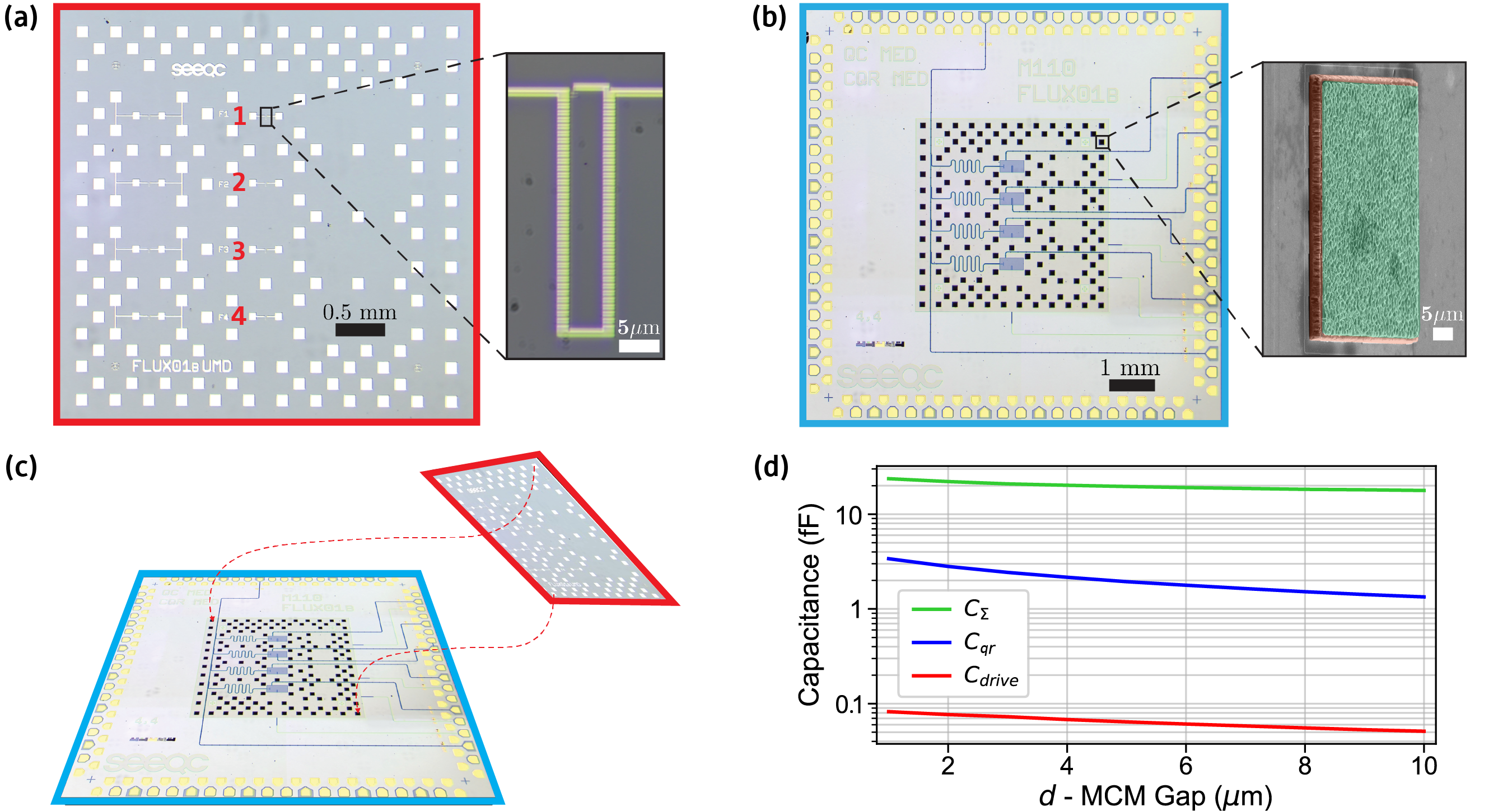
Our device consists of four uncoupled fluxonium circuits (labelled fluxoniums 1-4, see Figure 1) fabricated on a silicon chip, which is bump-bonded to the carrier chip with 5 m spacing. The passive carrier chip houses corresponding microwave control lines, DC lines for flux biasing, and coplanar waveguide (CPW) resonators [36] for readout. The fluxonium circuit design is the same as in references [25, 26], and can be further optimized for this new packaging method. All four circuits contain 138 large-area Josephson junctions in their superinductance arrays. The spectrum of the fluxonium circuits is varied by changing the Josephson energy . Fluxoniums 1 and 2 were designed to have about twice larger than 3 and 4. We targeted a qubit frequency of at least 1 GHz at the half flux sweet spot () in order to reduce the thermal population in the state and for a shorter gate duration.
Images of the device are shown in Figure 1. The capacitance between the two ends of the fluxonium, as well as to the readout resonator and control line, was simulated with Ansys Q3D (see Figure 1d). Both ends of the fluxonium are ungrounded and the capacitance to the carrier groundplane contributes the majority of the fluxonium capacitance. To reduce this capacitance to meet our target, we removed the groundplane from a area of the carrier centered over the fluxonium. To account for the presence of the flip-chip on resonator frequencies, the CPWs that comprise the resonators were simulated with Sonnet [37].
The bare fluxonium Hamiltonian reads [24]:
| (1) |
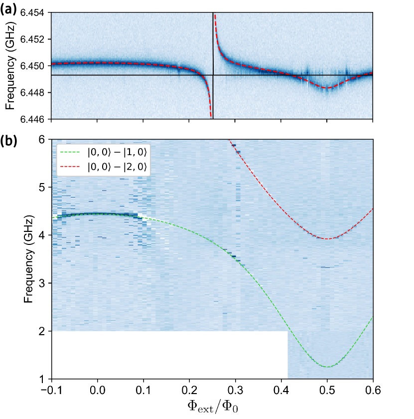
where the operators represent the displacement charge across the capacitance in units of Cooper pairs and the supercondicting phase across the inductance, respectively. They obey . Additionally, the resonator at frequency has the familiar Hamiltonian term: , and the Hamiltonian term for fluxonium-resonator coupling in the dispersive regime [38, 39] is given by: , where is the fluxonium-resonator coupling rate. The spectroscopy data in Figure 2 were fit to the numerical diagonalization of Hamiltonian: in the LC oscillator basis.
We extensively characterized fluxoniums 3 and 4 since they met our 1 GHz qubit frequency target, and focus on fluxonium 3 in the main text. The parameters for both circuits are summarized in Table 1. We began our analysis of fluxonium 3 with one- and two-tone spectroscopy of the resonator and fluxonium circuit (Figures 2a and 2b, respectively). Dispersive readout of the qubit was performed using the corresponding resonator at frequency , capacitively coupled to the fluxonium circuit with empirically determined coupling rate . The fit yields Josephson energy , inductive energy , and charging energy . The qubit transition frequency at the sweet spot is . We used a Hilbert space of 25 fluxonium levels and 5 resonator levels in the fits.
The fitted values for and correspond to inter-chip distances of 2.3 and 1.3 m, respectively. The discrepancy between the two distances can be explained by the fact that we did not account for lateral chip offsets nor chip tilt in the simulation, and depends more strongly on these variables than does. In general, a larger inter-chip distance will make the capacitances less sensitive to tilts, offsets, and variations in itself.
| Fluxonium | 3 | 4 |
|---|---|---|
| 2.50 | 2.36 | |
| 1.14 | 1.14 | |
| 0.89 | 0.89 | |
| 1.252 | 1.330 | |
| 2.14 | 1.99 | |
| 77 | 58 | |
| 38 | 33 | |
| 55.1 | 33.6 | |
| 27.5 | 23.2 | |
| 36.6 | 35.4 | |
| 6.4493 | 6.1391 | |
| 86 | 85 | |
| 1.39 | 0.63 | |
| 0.391 | 0.269 | |
| 1.6 | 2.0 | |
| 1.2 | 2.0 |
III Qubit Performance
We measured the energy relaxation time by applying a -pulse to the qubit and varying the readout delay. At maximum, s (see Figure 3a). The effective dielectric loss tangent of the total circuit capacitance corresponding to this maximal at qubit frequency 1.252 GHz is approximately . This value is similar to those reported in 3D fluxonium devices fabricated with the same materials and process [25], as well as in planar 2D architectures [35]. The effect of the MCM configuration on may vary, however, depending on the carrier groundplane geometry and the inter-chip distance. By optimizing the materials and fabrication process [40, 26], a reduction in by a factor of two is within reasonable expectation.
For calculating , it follows from Fermi’s Golden Rule that the decay rate between eigenstates due to dielectric loss [41] in the capacitor at a finite temperature reads [25, 35, 42]:
| (2) |
Here, is the fluxonium charge matrix element between states and in units of Cooper pairs. The loss tangent can be thought of as the inverse quality factor of the dielectric. We used Equation 2 to calculate corresponding loss tangents for fluxoniums 3 and 4, given their maximal values at the sweet spot. We assume a qubit temperature of , the approximate base temperature of the dilution refrigerator. Note that due to GHz in our experiments, the extracted depends weakly on the temperature. For example, mK would correspond to . Since can depend weakly on frequency, the reported values for fluxoniums 3 and 4 should be interpreted as the value at their qubit frequencies (see Table 1).
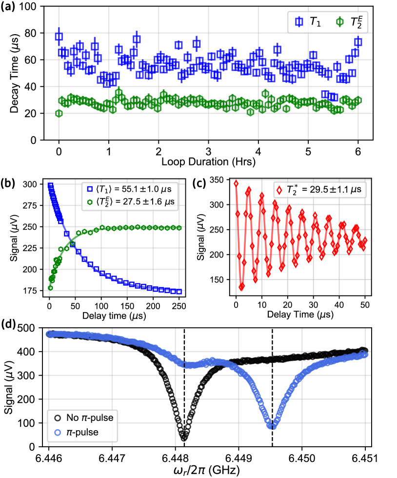
The coherence time was measured via Ramsey and Hahn-Echo experiments. In the Ramsey method [43], two -pulses are applied to the qubit, and the time delay between them is swept. Readout immediately follows the second -pulse. This pulse sequence yields Ramsey fringes with an exponentially decaying envelope with decay constant , the Ramsey coherence time. In the Hahn-Echo sequence [44], a -pulse is inserted between the two -pulses. This refocusing -pulse reverses any phase accumulation due to low-frequency drifts during the first half of the sequence [45]. By increasing the number of refocusing -pulses, known as a Carr-Purcell-Meiboom-Gill (CPMG) sequence [46], the qubit will become more sensitive to noise at successively higher frequencies [47]. At maximum, we measured s and Hahn-Echo coherence time s (Figures 3a, c).
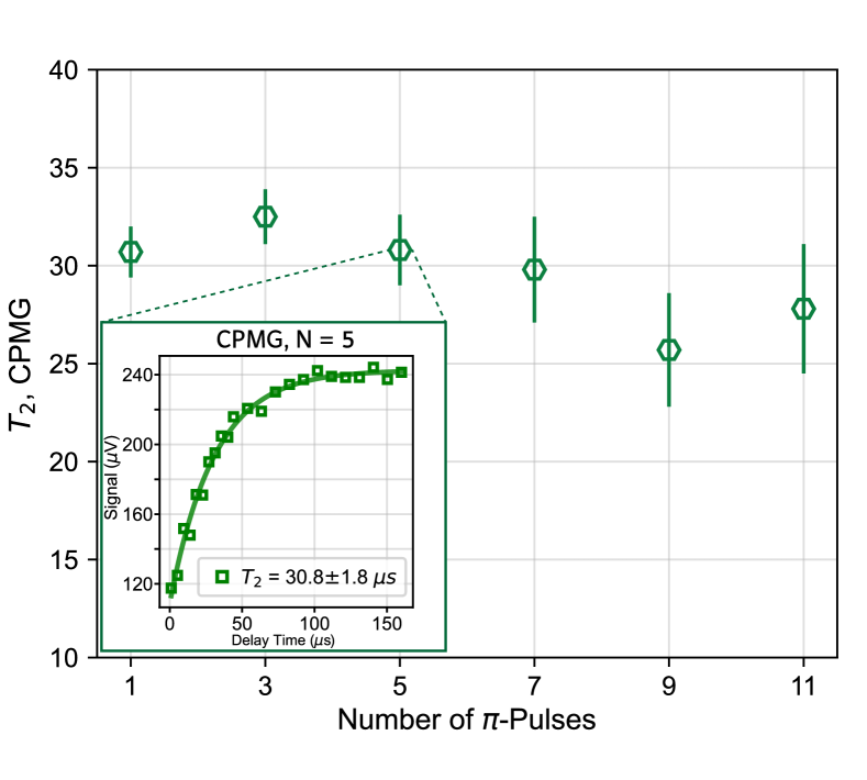
We performed an interleaved , loop to obtain statistics on the relaxation and coherence times of fluxonium 3, and found s and s. reveals significant pure dephasing of the qubit. We defined the dephasing time as , yielding s. The exponentially decaying Hahn-Echo and Ramsey signals (Figures 3b and c, respectfully) rule out flux noise [48, 49] as the predominant dephasing source. When we applied multiple refocusing pulses in a CPMG sequence, the measured decay time did not increase, indicating dephasing due to white noise (see Appendix B). It is therefore most likely that the pure dephasing of the qubit is caused by thermal photons in the resonator [50]. Based on the measured qubit dispersive shift and resonator linewidth (see Figure 3d and Table 1), s corresponds to an average thermal photon number of and an effective resonator temperature of (see Appendix A). Our measured values for and agree with those reported in transmon and flux qubits [51, 52, 53].
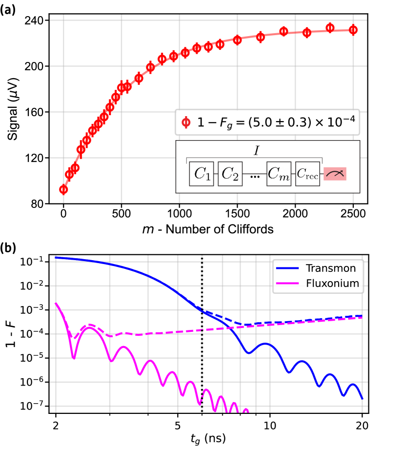
We completed our study of the fluxonium MCM by characterizing the single-qubit gates using randomized benchmarking (RB) [54, 55]. The Clifford gates were generated by the gate set ; we defined the identity gate as no pulse. An RB sequence is shown as an inset in Figure 4a. The physical pulses making up the gates were cosine-envelope microwave pulses with total gate duration . The gates were composed of two concatenated gates.
Figure 4a shows the results of the RB experiment on fluxonium 3, along with the fit, which yields an average Clifford gate error rate of and an average gate error rate of . Given s, and the average Clifford gate duration of 13 ns, we estimate the coherence limit for the Clifford gate error rate to be: . Comparing this estimate to the measured , we conclude that at least half of our gate error can be attributed to imperfect calibration. Additional pulse optimization, such as DRAG [56], can help approach the coherence limit. More details on the microwave pulses and measurement of the individual gate error rates from interleaved RB [55] are found in Appendix C.
In Figure 4b, we simulated the gate error rate versus total gate duration of a gate for fluxonium 3 (anharmonicity ) and a transmon (, , ). The anharmonicity is defined as . The solid curves are the gate error rate with no decoherence in the system, where state leakage outside of the computational subspace is the dominant error source. The dashed curves include relaxation and dephasing using the measured and of fluxonium 3. Details of the simulation are provided in Appendix C.
For in our experiments, the simulated coherence limit on the gate error rate is . Given the measured error rate (see Table 2) of , we estimate that 48% of the gate error is due to decoherence. The discrepancy between the measured gate error rate and the coherence limit can be attributed to the 1 GSa/s sampling rate of the AWG. In the simulation, we assume a nearly continuous pulse envelope, while in practice this cannot be achieved as we approach .
Crucially, Figure 4b shows that it is impossible to reach the same gate error rates using basic (no DRAG) microwave pulses on a typical transmon qubit, even without decoherence. Due to fluxonium’s higher anharmonicity, such a short gate time is accessible. Only at a gate duration of around 3 ns does the error rate become dominated by state leakage. Consequently, we could achieve a state-of-the-art gate fidelity in this device, despite a lower coherence time.
IV Conclusion
In conclusion, we have packaged fluxonium qubits in a multi-chip module, and demonstrated performance on par with the previously cited experiments in 2D and 3D packages. An effective resonator temperature of 70 mK and average thermal photon number is sufficient to explain the measured . By optimizing the readout line filtering and attenuation, along with reducing , we expect the coherence time to approach the limit.
Despite the high level of pure dephasing, a single-qubit gate fidelity greater than 0.999 was possible by using 6 ns pulses. A conservative goal of doubling the reported , without any improvement of , would push the coherence limit on the gate fidelity to above 0.9999. Fast gates, calibrated in a straightforward manner, are a key advantage of fluxonium, where the anharmonicity is about an order of magnitude larger than in transmons. Our results on the first fluxonium MCM may be useful for scaling the next generation of fluxonium-based quantum processors.
We acknowledge contributions from SEEQC foundry engineers John Vivalda and Asa Chambal-Jacobs.
Appendix
IV.1 Readout
IV.1.1 Qubit-Resonator Interaction
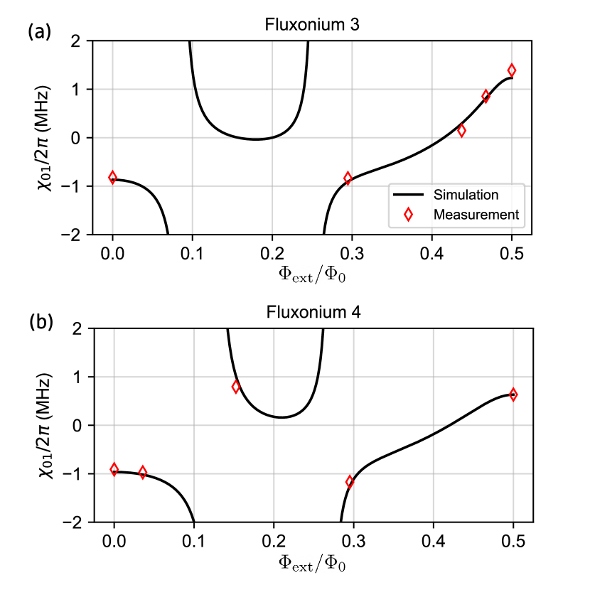
Each fluxonium circuit is capacitively coupled to a CPW resonator, which is housed on the carrier chip. The fluxonium-resonator coupling rate was found empirically by fitting the spectroscopy data in Figure 2. The pull on the resonator frequency due to bare fluxonium state , known as the dispersive shift of state , is given by [57]:
| (3) |
The dispersive shift of the transition between states and is then . Crucially, Equation 3 shows that the qubit transition can have a large dispersive shift due to the contributions of the higher levels where , despite the large detuning between and . Figure 5 uses Equation 3 to plot across half a flux period for fluxoniums 3 and 4. Red diamonds are measured at various external flux biases, showing excellent agreement between theory and experiment. The simulation uses 25 fluxonium levels, 20 of which are used in the summation to find .
In our system, the fluxonium-resonator coupling rate in Equation 3 is given by:
| (4) |
where and are the fluxonium and resonator characteristic impedances, respectfully. is the resistance quantum.
IV.1.2 Thermal Photon Dephasing
The qubit dephasing rate due to thermal photons in the cavity is given by:
| (5) |
in the low photon number limit [58, 51]. Plugging in the values of , , and for each fluxonium (see Table 1), we find the average thermal photon numbers and for fluxoniums 3 and 4, respectively. These values correspond to resonator temperatures of and for fluxoniums 3 and 4, respectively.
IV.2 Coherence Analysis
IV.2.1 Flux Noise
flux noise is known to be a leading cause of pure dephasing in flux-sensitive qubits, with a noise spectral density [45, 48, 59, 49, 53]:
| (6) |
where is the flux noise amplitude at 1 Hz. The dephasing rate due to first-order flux noise is given by:
| (7) |
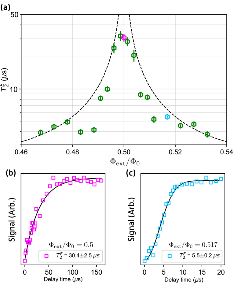
This leads to a measurement signal decaying with a Gaussian envelope, with decay constant . This is the case when fluxonium is flux biased off of the sweet spot. On the sweet spot, the first-order sensitivity to flux noise vanishes, and we observe an exponentially decaying echo signal [25]. To determine in our experimental setup, we measured at various in fluxonium 3 (see Figure 6). The observed dependence of versus external flux bias corresponds to , which is similar to the previously cited work.
IV.2.2 CPMG
By increasing the number of refocusing -pulses in a Hahn-Echo sequence (where ), the qubit will be more sensitive to noise at successively higher frequencies [45, 60]. This is known as a Carr-Purcell-Meiboom-Gill (CPMG) sequence [46], where the additional refocusing -pulses act as a bandpass filter centered at a frequency determined by and the free evolution time [47, 53]. If the noise spectrum is white within the region we sweep our filter, we expect the measured decay time to remain constant with an increasing number of -pulses. If the noise spectral density , we expect to rise for . Given the results of our CPMG experiment shown in Figure 7, we concluded that thermal resonator photons are the main dephasing source at the sweet spot.
IV.3 Single-Qubit Gates
IV.3.1 Microwave Pulses
The and pulses were synthesized with a Keysight M3202 AWG and a Rohde & Schwarz SGS100A Vector Modulation RF source for low frequency IQ modulation. We used cosine-envelope pulses with an envelope function:
| (8) |
where is the drive amplitude and is the total gate duration. We set in our experiments. The cosine envelope is chosen over Gaussian to avoid truncation at the edges. The () pulses consist of pairs of concatenated ( pulses. We tuned the qubit drive frequency by taking Ramsey measurements with varying . After obtaining the , we performed a pulse train measurement to determine the optimal pulse amplitude. The pulse train consisted of sweeping the amplitude for a train of 4, 16, 36, 64, 100, and 144 pulses. The resulting trace of each measurement is effectively a Rabi oscillation, where the Rabi frequency increases with the number of pulses in the train. The amplitude corresponding to the same phase in the Rabi oscillations across all the trains is the optimal pulse amplitude. After performing initial randomized benchmarking experiments, the pulse amplitude was further fine-tuned using the ORBIT procedure [61].
IV.3.2 Single-Qubit Randomized Benchmarking
We benchmarked the single-qubit gates in fluxoniums 3 and 4 using randomized benchmarking (RB) [54]. In the RB sequence, randomly chosen Clifford gates are applied to the qubit before applying a single recovery gate, such that the entire sequence is tantamount to an identity operation. In practice, due to decoherence and sub-optimal pulse parameters, the RB signal decays with the number of Clifford gates in the sequence as:
| (9) |
where is the depolarization parameter, and are constants. We extract by fitting the measured RB signal to Equation 9 (see Figure 4). The average error rate of a single-qubit Clifford operation is then given by:
| (10) |
Since each Clifford operation is composed on average of 1.833 physical gates (we don’t count the identity gate), the average physical gate fidelity is:
| (11) |
We estimated the lower limit on the gate error rate by taking .
To determine the individual gate fidelities we performed interleaved randomized benchmarking [55]. The error rates of each gate, , are given in Table 2. In the interleaved RB sequence, a given gate is interleaved between each Clifford operation. The resulting curve follows the same decay profile as the standard RB, but with a depolarization parameter . The gate error is then given by:
| (12) |
where is the depolarization parameter obtained from the initial RB and is the fidelity of the interleaved gate.
| Gate | X | X/2 | -X/2 | Y | Y/2 | -Y/2 |
|---|---|---|---|---|---|---|
| 8.1 | 3.1 | 2.6 | 6.1 | 2.1 | 5.9 |
IV.3.3 Gate Simulation
The simulation results shown in Figure 4b were obtained as follows. We truncated the fluxonium and transmon Hamiltonians to only consider the five lowest energy eigenstates. We then define a pulse with driving frequency , and envelope given by Equation 8, and compute the evolution operator governing the time dynamics of the circuit when the pulse is applied. Sweeping the gate time , we optimize the amplitude and drive frequency of the pulse using Sequential Least Squares Programming to minimize the gate error rate , where the gate fidelity is defined as [62]:
| (13) |
where , or a gate. Note that is non-unitary due to driving of higher energy circuit transitions.
To simulate the gate error with decoherence, we used the Lindblad master equation to model the evolution of the density matrix with the optimal pulse parameters obtained from the simulation without decoherence. We included two collapse operators representing relaxation from qubit excited to ground state, and pure dephasing between the qubit states, following the procedure presented in [63].
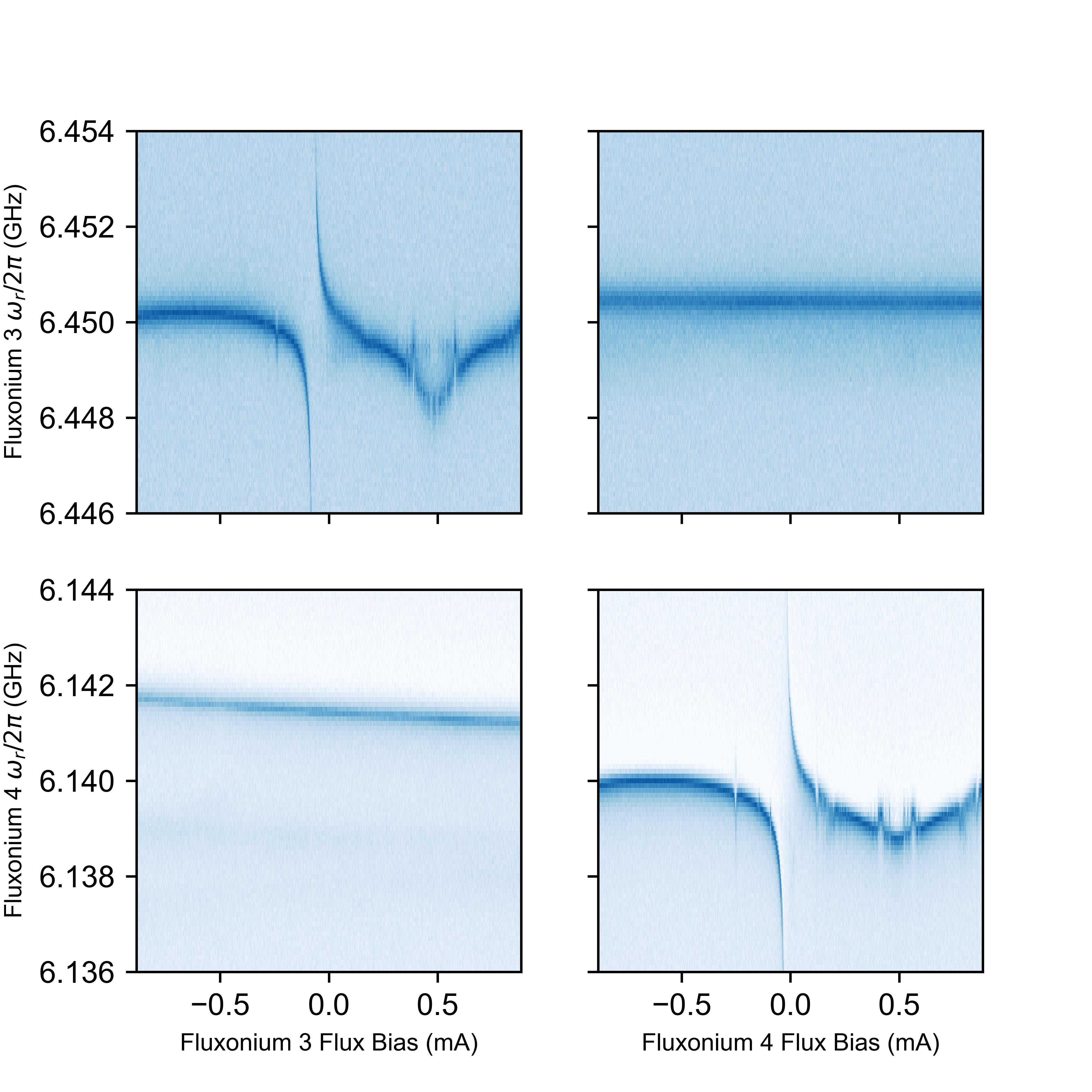
IV.4 Flux Bias Crosstalk
We performed resonator spectroscopy on both fluxoniums 3 and 4 while tuning their respective external flux biases. We constructed a flux crosstalk matrix (Figure 8) to quantify the mutual inductance between the flux bias line of fluxonium 3 and fluxonium 4’s superinductance loop, and vice versa. The mutual inductance between the fluxonium circuit loop and flux bias line for fluxoniums 3 and 4 is 2.27 and 2.23 , respectively. This is determined using the diagonal elements of the flux crosstalk matrix. The mutual inductance between fluxonium 4 and fluxonium 3’s bias line is 430 . Fluxonium 3’s resonator frequency did not shift over the current range of fluxonium 4’s bias line, therefore this mutual inductance is negligible.
IV.5 Fabrication
IV.5.1 Quantum Chip
We fabricated the device on a high resistivity silicon substrate. Cleaning: The chip is prepared by sonicating it in acetone, then isopropyl alcohol (IPA) for 3 minutes each. Electron Beam Resist Application: 1 drop of MMA EL-13 electron beam resist is applied to the chip, then spun at 5000 RPM for 1 minute. The resist is then baked on a hotplate for 1 minute at C. A second layer of resist is then applied: 1 drop of 950 PMMA A3 electron beam resist spun at 4000 RPM for 1 minute before baking at C for 30 minutes. Electron Beam Lithography: The circuit is written with a 100 kV Elionix Electron Beam Lithography system, using a beam current of 1 nA. Resist Development: Mask is developed for 2 minutes in a 3:1 IPA:DI solution at C. The chip is lightly shaken back and forth by hand at around 1-2 Hz while in the developer. Metal Deposition: Chip is loaded into a Plassys deposition system and the loadlock is pumped on for 20 hours until the pressure reaches mBar prior to deposition. The deposition is comprised of the following steps: 1. 20 second Ar etch at each deposition angle () 2. Deposit Ti into the chamber at 0.1 nm/s for 2 minutes 3. First Al deposition: 20 nm is deposited at 1 nm/s at an angle of 4. 10 minutes of oxidation at 100 mBar 5. Second Al deposition: 40 nm is deposited at 1 nm/s at an angle of 6. 20 minutes of oxidation at 10 mBar (capping). Resist Liftoff: Chip is bathed in acetone for 3 hours at C. Then it is sonicated in the acetone for 5 seconds, followed by 10 seconds of sonication in IPA. Finally, chip is blown dry with .
IV.5.2 Carrier Chip
The process is based on SEEQC’s two-niobium-superconducting-layers recipe for quantum applications [64]. The process involves substrate preparation, niobium (Nb) sputtering, plasma enhanced chemical vapor deposition (PECVD) of /, chemical mechanical polishing (CMP), photolithography, and dry etching. The substrate is a high resistivity 6 inch (150 mm) silicon wafer.
It is first cleaned by spin scrubbing with acetone and spin rinse drying with IPA. Then the native oxide on the wafer is removed by BOE prior to loading into the deposition chamber. Once the chamber reaches a base pressure of mBar, Nb is deposited by DC sputtering with target thickness 200 nm. The coplanar microstrip lines, feedthroughs, resonators, and qubit control lines are then pattered in this layer. All the patterning for this process is done using a maskless laser writer capable of resolving features with an i-line resist process. Then the Nb is inductively coupled plasma (ICP) etched in chlorine chemistry optimized for good selectivity to silicon. Moreover, an endpoint detection was implemented to minimize the overetch into the substrate and to keep the overetch to within nm. Next, the resist is stripped in an acetone sonicating bath, followed by 600 nm of low loss PECVD deposited with CMP to planarize the layer. The wafer is then coated with PECVD of thickness 150 nm for an inter-layer dielectric. The vias to the bottom Nb layer are then patterned and dry etched, which opens access to the wring, grounds, bump and contact pad connections. Then a second Nb layer of thickness 300 nm is deposited, followed by patterning of the wiring, ground straps, and contacts. The Nb is then dry etched in reactive ion etcher (RIE); at this step the exposed dielectric is completely dry etched from the wafer to minimize the dielectric participation ratio. After this step, there is only dielectric remaining under the wiring and ground straps. Next, the contact pads are patterned: trilayer Mo/Pd/Au of thickness 40 nm/100 nm/200 nm is deposited and lifted off. Finally, the bump layer is patterned: Al/In of thickness 5 m/1 m is deposited and lifted off. The carrier chips of size 10 10 are then diced out and ready for flip-chip bonding.
IV.5.3 Multi-Chip Module
The multi-chip module was assembled using a Karl Suss / Microtec FC 150 Flip-Chip Bonder. The tool holds the chip and carrier on two vacuum chucks while adjusting the relative position of alignment marks viewed through a two-objective microscope assembly. The bonder was calibrated immediately before MCM assembly, such that the lateral misalignment between chip and carrier is within 1 m. The chip and carrier are aligned parallel to within 25 rad, as specified by the tool.
The MCM was assembled by a cold compression process with a force of 294 , held constant for 2 minutes. Distributed over the 152 square bumps, each 120 m wide (8.8% of the total flip-chip area), this force is equivalent to 197 grams per bump. Post-bond measurement of bump height on other MCMs has indicated that this force compresses the top 1 m layer of indium, but does not significantly compress the underlying aluminum bump, such that the aluminum acts as a hard stop to control inter-chip spacing. After bonding, a small amount of low-temperature microelectronic-compatible epoxy was applied to the corners of the chip, away from critical circuit components, to maintain integrity of the MCM during sample handling and installation.
IV.6 Experimental Setup
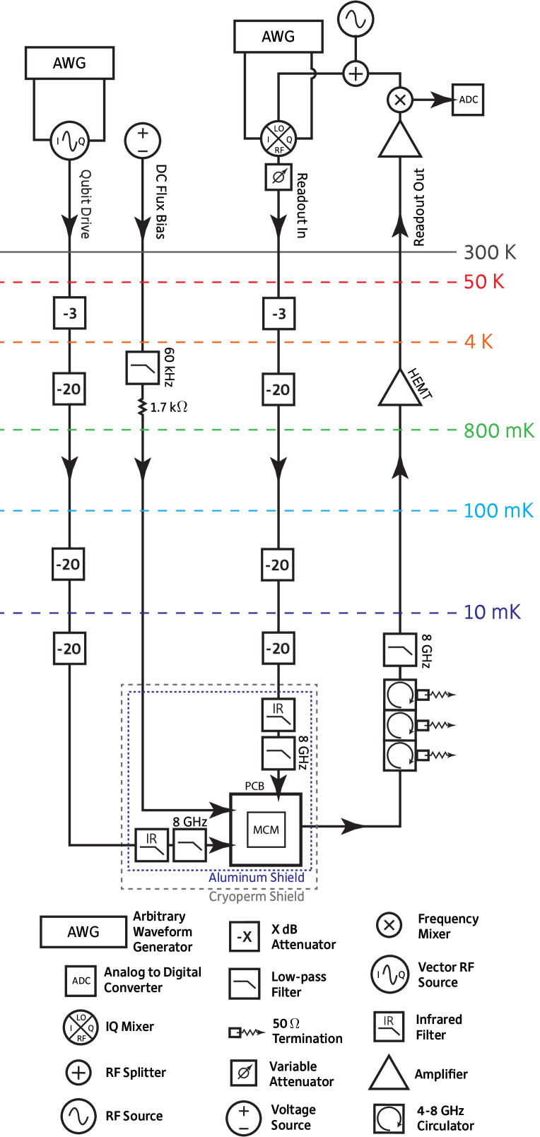
The experiment was performed in a BlueFors LD400 dilution refrigerator (DR) at a base temperature of . The driving and readout lines were attenuated and filtered as depicted in Figure 9. The MCM was mounted and wirebonded to a printed circuit board (PCB), which in turn was housed in a copper package. This package was bolted to a coldfinger extending from the 10 mK stage of the DR. The device package was encased in a superconducting (aluminum) shield as well as a cryoperm shield. Additionally, we used a magnetic shield inside the outer vacuum can of the refrigerator.
References
- Devoret and Schoelkopf [2013] M. H. Devoret and R. J. Schoelkopf, Superconducting circuits for quantum information: An outlook, Science 339, 1169 (2013).
- Kjaergaard et al. [2020] M. Kjaergaard, M. E. Schwartz, J. Braumüller, P. Krantz, J. I.-J. Wang, S. Gustavsson, and W. D. Oliver, Superconducting Qubits: Current State of Play, Annu. Rev. Condens. Matter Phys. 11, 369 (2020).
- Schoelkopf and Girvin [2008] R. J. Schoelkopf and S. M. Girvin, Wiring up quantum systems, Nature 451, 664 (2008).
- Arute et al. [2019] F. Arute, K. Arya, R. Babbush, D. Bacon, J. C. Bardin, R. Barends, R. Biswas, S. Boixo, F. G. Brandao, D. A. Buell, B. Burkett, Y. Chen, Z. Chen, B. Chiaro, R. Collins, W. Courtney, A. Dunsworth, E. Farhi, B. Foxen, A. Fowler, C. Gidney, M. Giustina, R. Graff, K. Guerin, S. Habegger, M. P. Harrigan, M. J. Hartmann, A. Ho, M. Hoffmann, T. Huang, T. S. Humble, S. V. Isakov, E. Jeffrey, Z. Jiang, D. Kafri, K. Kechedzhi, J. Kelly, P. V. Klimov, S. Knysh, A. Korotkov, F. Kostritsa, D. Landhuis, M. Lindmark, E. Lucero, D. Lyakh, S. Mandrà, J. R. McClean, M. McEwen, A. Megrant, X. Mi, K. Michielsen, M. Mohseni, J. Mutus, O. Naaman, M. Neeley, C. Neill, M. Y. Niu, E. Ostby, A. Petukhov, J. C. Platt, C. Quintana, E. G. Rieffel, P. Roushan, N. C. Rubin, D. Sank, K. J. Satzinger, V. Smelyanskiy, K. J. Sung, M. D. Trevithick, A. Vainsencher, B. Villalonga, T. White, Z. J. Yao, P. Yeh, A. Zalcman, H. Neven, and J. M. Martinis, Quantum supremacy using a programmable superconducting processor, Nature 574, 505 (2019).
- Zhang et al. [2022] E. J. Zhang, S. Srinivasan, N. Sundaresan, D. F. Bogorin, Y. Martin, J. B. Hertzberg, J. Timmerwilke, E. J. Pritchett, J.-B. Yau, C. Wang, W. Landers, E. P. Lewandowski, A. Narasgond, S. Rosenblatt, G. A. Keefe, I. Lauer, M. B. Rothwell, D. T. McClure, O. E. Dial, J. S. Orcutt, M. Brink, and J. M. Chow, High-fidelity superconducting quantum processors via laser-annealing of transmon qubits, Sci. Adv. 8, 19 (2022).
- Fowler et al. [2012] A. G. Fowler, M. Mariantoni, J. M. Martinis, and A. N. Cleland, Surface codes: Towards practical large-scale quantum computation, Phys. Rev. A 86, 032324 (2012).
- McDermott et al. [2018] R. McDermott, M. G. Vavilov, B. L. Plourde, F. K. Wilhelm, P. J. Liebermann, O. A. Mukhanov, and T. A. Ohki, Quantum-classical interface based on single flux quantum digital logic, Quantum Sci. Technol. 3, 024004 (2018).
- Leonard et al. [2019] E. Leonard, M. A. Beck, J. Nelson, B. G. Christensen, T. Thorbeck, C. Howington, A. Opremcak, I. V. Pechenezhskiy, K. Dodge, N. P. Dupuis, M. D. Hutchings, J. Ku, F. Schlenker, J. Suttle, C. Wilen, S. Zhu, M. G. Vavilov, B. L. Plourde, and R. McDermott, Digital Coherent Control of a Superconducting Qubit, Phys. Rev. Applied 11, 014009 (2019).
- Brecht et al. [2016] T. A. Brecht, W. Pfaff, C. Wang, Y. Chu, L. Frunzio, M. H. Devoret, and R. J. Schoelkopf, Multilayer microwave integrated quantum circuits for scalable quantum computing, npj Quantum Inf. 2, 16002 (2016).
- Foxen et al. [2018] B. Foxen, J. Y. Mutus, E. Lucero, R. Graff, A. Megrant, Y. Chen, C. Quintana, B. Burkett, J. Kelly, E. Jeffrey, Y. Yang, A. Yu, K. Arya, R. Barends, Z. Chen, B. Chiaro, A. Dunsworth, A. Fowler, C. Gidney, M. Giustina, T. Huang, P. Klimov, M. Neeley, C. Neill, P. Roushan, D. Sank, A. Vainsencher, J. Wenner, T. C. White, and J. M. Martinis, Qubit compatible superconducting interconnects, Quantum Sci. Technol. 3, 014005 (2018).
- Dunsworth et al. [2018] A. Dunsworth, R. Barends, Y. Chen, Z. Chen, B. Chiaro, A. Fowler, B. Foxen, E. Jeffrey, J. Kelly, P. V. Klimov, E. Lucero, J. Y. Mutus, M. Neeley, C. Neill, C. Quintana, P. Roushan, D. Sank, A. Vainsencher, J. Wenner, T. C. White, H. Neven, J. M. Martinis, and A. Megrant, A method for building low loss multi-layer wiring for superconducting microwave devices, Appl. Phys. Lett. 112, 063502 (2018).
- Yost et al. [2020] D. R. Yost, M. E. Schwartz, J. Mallek, D. Rosenberg, C. Stull, J. L. Yoder, G. Calusine, M. Cook, R. Das, A. L. Day, E. B. Golden, D. K. Kim, A. Melville, B. M. Niedzielski, W. Woods, A. J. Kerman, and W. D. Oliver, Solid-state qubits integrated with superconducting through-silicon vias, npj Quantum Inf. 6, 59 (2020).
- Catelani et al. [2011] G. Catelani, R. J. Schoelkopf, M. H. Devoret, and L. I. Glazman, Relaxation and frequency shifts induced by quasiparticles in superconducting qubits, Phys. Rev. B 84, 064517 (2011).
- Glazman and Catelani [2021] L. I. Glazman and G. Catelani, Bogoliubov Quasiparticles in Superconducting Qubits, SciPost Phys. Lect. Notes 31 (2021).
- Liu et al. [2023] C. Liu, A. Ballard, D. Olaya, D. Schmidt, J. Biesecker, T. Lucas, J. Ullom, S. Patel, O. Rafferty, A. Opremcak, K. Dodge, V. Iaia, T. McBroom, J. DuBois, P. Hopkins, S. Benz, B. Plourde, and R. McDermott, Single Flux Quantum-Based Digital Control of Superconducting Qubits in a Multichip Module, PRX Quantum 4, 030310 (2023).
- Koch et al. [2007a] J. Koch, T. M. Yu, J. Gambetta, A. A. Houck, D. I. Schuster, J. Majer, A. Blais, M. H. Devoret, S. M. Girvin, and R. J. Schoelkopf, Charge-insensitive qubit design derived from the Cooper pair box, Phys. Rev. A 76, 042319 (2007a).
- You et al. [2007] J. Q. You, X. Hu, S. Ashhab, and F. Nori, Low-decoherence flux qubit, Phys. Rev. B 75, 140515 (2007).
- Steffen et al. [2010] M. Steffen, S. Kumar, D. P. Divincenzo, J. R. Rozen, G. A. Keefe, M. B. Rothwell, and M. B. Ketchen, High-Coherence Hybrid Superconducting Qubit, Phys. Rev. Lett. 105, 100502 (2010).
- Rosenberg et al. [2017] D. Rosenberg, D. Kim, R. Das, D. Yost, S. Gustavsson, D. Hover, P. Krantz, A. Melville, L. Racz, G. O. Samach, S. J. Weber, F. Yan, J. L. Yoder, A. J. Kerman, and W. D. Oliver, 3D integrated superconducting qubits, npj Quantum Inf. 3, 42 (2017).
- Li et al. [2021] X. Li, Y. Zhang, C. Yang, Z. Li, J. Wang, T. Su, M. Chen, Y. Li, C. Li, Z. Mi, X. Liang, C. Wang, Z. Yang, Y. Feng, K. Linghu, H. Xu, J. Han, W. Liu, P. Zhao, T. Ma, R. Wang, J. Zhang, Y. Song, P. Liu, Z. Wang, Z. Yang, G. Xue, Y. Jin, and H. Yu, Vacuum-gap transmon qubits realized using flip-chip technology, Appl. Phys. Lett. 119, 184003 (2021).
- Kosen et al. [2022] S. Kosen, H.-X. Li, M. Rommel, D. Shiri, C. Warren, L. Grönberg, J. Salonen, T. Abad, J. Biznárová, M. Caputo, L. Chen, K. Grigoras, G. Johansson, A. F. Kockum, C. Križan, D. P. Lozano, G. Norris, A. Osman, J. Fernández-Pendás, A. Ronzani, A. F. Roudsari, S. Simbierowicz, G. Tancredi, A. Wallraff, C. Eichler, J. Govenius, and J. Bylander, Building Blocks of a Flip-Chip Integrated Superconducting Quantum Processor, Quantum Sci. Technol. 7, 035018 (2022).
- Jurcevic et al. [2021] P. Jurcevic, A. Javadi-Abhari, L. S. Bishop, I. Lauer, D. F. Bogorin, M. Brink, L. Capelluto, O. Günlük, T. Itoko, N. Kanazawa, A. Kandala, G. A. Keefe, K. Krsulich, W. Landers, E. P. Lewandowski, D. T. McClure, G. Nannicini, A. Narasgond, H. M. Nayfeh, E. Pritchett, M. B. Rothwell, S. Srinivasan, N. Sundaresan, C. Wang, K. X. Wei, C. J. Wood, J. B. Yau, E. J. Zhang, O. E. Dial, J. M. Chow, and J. M. Gambetta, Demonstration of quantum volume 64 on a superconducting quantum computing system, Quantum Sci. Technol. 6, 025020 (2021).
- Gold et al. [2021] A. Gold, J. P. Paquette, A. Stockklauser, M. J. Reagor, M. S. Alam, A. Bestwick, N. Didier, A. Nersisyan, F. Oruc, A. Razavi, B. Scharmann, E. A. Sete, B. Sur, D. Venturelli, C. J. Winkleblack, F. Wudarski, M. Harburn, and C. Rigetti, Entanglement across separate silicon dies in a modular superconducting qubit device, npj Quantum Inf. 7, 142 (2021).
- Manucharyan et al. [2009] V. E. Manucharyan, J. Koch, L. I. Glazman, and M. H. Devoret, Fluxonium: Single cooper-pair circuit free of charge offsets, Science 326, 113 (2009).
- Nguyen et al. [2019] L. B. Nguyen, Y. H. Lin, A. Somoroff, R. Mencia, N. Grabon, and V. E. Manucharyan, High-Coherence Fluxonium Qubit, Phys. Rev. X 9, 041041 (2019).
- Somoroff et al. [2023] A. Somoroff, Q. Ficheux, R. A. Mencia, H. Xiong, R. Kuzmin, and V. E. Manucharyan, Millisecond Coherence in a Superconducting Qubit, Phys. Rev. Lett. 130, 267001 (2023).
- Chen et al. [2016] Z. Chen, J. Kelly, C. Quintana, R. Barends, B. Campbell, Y. Chen, B. Chiaro, A. Dunsworth, A. G. Fowler, E. Lucero, E. Jeffrey, A. Megrant, J. Mutus, M. Neeley, C. Neill, P. J. O’Malley, P. Roushan, D. Sank, A. Vainsencher, J. Wenner, T. C. White, A. N. Korotkov, and J. M. Martinis, Measuring and Suppressing Quantum State Leakage in a Superconducting Qubit, Phys. Rev. Lett. 116, 020501 (2016).
- Ficheux et al. [2021] Q. Ficheux, L. B. Nguyen, A. Somoroff, H. Xiong, K. N. Nesterov, M. G. Vavilov, and V. E. Manucharyan, Fast Logic with Slow Qubits: Microwave-Activated Controlled-Z Gate on Low-Frequency Fluxoniums, Phys. Rev. X 11, 021026 (2021).
- Xiong et al. [2022] H. Xiong, Q. Ficheux, A. Somoroff, L. B. Nguyen, E. Dogan, D. Rosenstock, C. Wang, K. N. Nesterov, M. G. Vavilov, and V. E. Manucharyan, Arbitrary controlled-phase gate on fluxonium qubits using differential ac Stark shifts, Phys. Rev. Research 4, 023040 (2022).
- Dogan et al. [2023] E. Dogan, D. Rosenstock, L. Le Guevel, H. Xiong, R. A. Mencia, A. Somoroff, K. N. Nesterov, M. G. Vavilov, V. E. Manucharyan, and C. Wang, Two-Fluxonium Cross-Resonance Gate, Phys. Rev. Applied 20, 024011 (2023).
- Moskalenko et al. [2022] I. N. Moskalenko, I. A. Simakov, N. N. Abramov, A. A. Grigorev, D. O. Moskalev, A. A. Pishchimova, N. S. Smirnov, E. V. Zikiy, I. A. Rodionov, and I. S. Besedin, High fidelity two-qubit gates on fluxoniums using a tunable coupler, npj Quantum Inf. 8, 130 (2022).
- Bao et al. [2021] F. Bao, H. Deng, D. Ding, R. Gao, X. Gao, C. Huang, X. Jiang, H.-S. Ku, Z. Li, X. Ma, X. Ni, J. Qin, Z. Song, H. Sun, C. Tang, T. Wang, F. Wu, T. Xia, W. Yu, F. Zhang, G. Zhang, X. Zhang, J. Zhou, X. Zhu, Y. Shi, J. Chen, H.-H. Zhao, and C. Deng, Fluxonium: an alternative qubit platform for high-fidelity operations, Phys. Rev. Lett. 129, 010502 (2021).
- Ding et al. [2023] L. Ding, M. Hays, Y. Sung, B. Kannan, J. An, A. Di Paolo, A. H. Karamlou, T. M. Hazard, K. Azar, D. K. Kim, B. M. Niedzielski, A. Melville, M. E. Schwartz, J. L. Yoder, T. P. Orlando, S. Gustavsson, J. A. Grover, K. Serniak, and W. D. Oliver, High-Fidelity, Frequency-Flexible Two-Qubit Fluxonium Gates with a Transmon Coupler, arXiv:2304.06087 (2023).
- Nguyen et al. [2022] L. B. Nguyen, G. Koolstra, Y. Kim, A. Morvan, T. Chistolini, S. Singh, K. N. Nesterov, C. Jünger, L. Chen, Z. Pedramrazi, B. K. Mitchell, J. M. Kreikebaum, S. Puri, D. I. Santiago, and I. Siddiqi, Scalable High-Performance Fluxonium Quantum Processor, PRX Quantum 3, 037001 (2022).
- Zhang et al. [2021] H. Zhang, S. Chakram, T. Roy, N. Earnest, Y. Lu, Z. Huang, D. K. Weiss, J. Koch, and D. I. Schuster, Universal Fast-Flux Control of a Coherent, Low-Frequency Qubit, Phys. Rev. X 11, 011010 (2021).
- Göppl et al. [2008] M. Göppl, A. Fragner, M. Baur, R. Bianchetti, S. Filipp, J. M. Fink, P. J. Leek, G. Puebla, L. Steffen, and A. Wallraff, Coplanar waveguide resonators for circuit quantum electrodynamics, J. Appl. Phys. 104, 113904 (2008).
- [37] Sonnet Suites Software.
- Wallraff et al. [2004] A. Wallraff, D. I. Schuster, A. Blais, L. Frunzio, R. S. Huang, J. Majer, S. Kumar, S. M. Girvin, and R. J. Schoelkopf, Strong coupling of a single photon to a superconducting qubit using circuit quantum electrodynamics, Nature 431, 162 (2004).
- Blais et al. [2004] A. Blais, R.-S. Huang, A. Wallraff, S. M. Girvin, and R. J. Schoelkopf, Cavity quantum electrodynamics for superconducting electrical circuits: An architecture for quantum computation, Phys. Rev. A 69, 062320 (2004).
- Place et al. [2021] A. P. Place, L. V. Rodgers, P. Mundada, B. M. Smitham, M. Fitzpatrick, Z. Leng, A. Premkumar, J. Bryon, S. Sussman, G. Cheng, T. Madhavan, H. K. Babla, B. Jäck, A. Gyenis, N. Yao, R. J. Cava, N. P. de Leon, and A. A. Houck, New material platform for superconducting transmon qubits with coherence times exceeding 0.3 milliseconds, Nat. Commun. 12, 1779 (2021).
- Martinis et al. [2005] J. M. Martinis, K. B. Cooper, R. McDermott, M. Steffen, M. Ansmann, K. D. Osborn, K. Cicak, S. Oh, D. P. Pappas, R. W. Simmonds, and C. C. Yu, Decoherence in Josephson qubits from dielectric Loss, Phys. Rev. Lett. 95, 210503 (2005).
- Masluk [2012] N. A. Masluk, Reducing the losses of the fluxonium artificial atom, Ph.D. thesis, Yale University (2012).
- Ramsey [1950] N. F. Ramsey, A molecular beam resonance method with separated oscillating fields, Phys. Rev. 78, 695 (1950).
- Hahn [1950] E. Hahn, Spin Echoes, Phys. Rev. 80, 580 (1950).
- Martinis et al. [2003] J. M. Martinis, S. Nam, J. Aumentado, K. M. Lang, and C. Urbina, Decoherence of a superconducting qubit due to bias noise, Phys. Rev. B 67, 094510 (2003).
- Meiboom and Gill [1958] S. Meiboom and D. Gill, Modified spin-echo method for measuring nuclear relaxation times, Rev. Sci. Instrum. 29, 688 (1958).
- Bylander et al. [2011] J. Bylander, S. Gustavsson, F. Yan, F. Yoshihara, K. Harrabi, G. Fitch, D. G. Cory, Y. Nakamura, J. S. Tsai, and W. D. Oliver, Noise spectroscopy through dynamical decoupling with a superconducting flux qubit, Nat. Phys. 7, 565 (2011).
- Yoshihara et al. [2006] F. Yoshihara, K. Harrabi, A. O. Niskanen, Y. Nakamura, and J. S. Tsai, Decoherence of flux qubits due to 1/f flux noise, Phys. Rev. Lett. 97, 167001 (2006).
- Kumar et al. [2016] P. Kumar, S. Sendelbach, M. A. Beck, J. W. Freeland, Z. Wang, H. Wang, C. C. Yu, R. Q. Wu, D. P. Pappas, and R. McDermott, Origin and Reduction of 1 /f Magnetic Flux Noise in Superconducting Devices, Phys. Rev. Applied 6, 041001 (2016).
- Bertet et al. [2005] P. Bertet, I. Chiorescu, G. Burkard, K. Semba, C. J. Harmans, D. P. Divincenzo, and J. E. Mooij, Dephasing of a superconducting qubit induced by photon noise, Phys. Rev. Lett. 95, 257002 (2005).
- Wang et al. [2019] Z. Wang, S. Shankar, Z. K. Minev, P. Campagne-Ibarcq, A. Narla, and M. H. Devoret, Cavity Attenuators for Superconducting Qubits, Phys. Rev. Applied 11, 014031 (2019).
- Yeh et al. [2017] J. H. Yeh, J. Lefebvre, S. Premaratne, F. C. Wellstood, and B. S. Palmer, Microwave attenuators for use with quantum devices below 100 mK, J. Appl. Phys. 121, 224501 (2017).
- Yan et al. [2016] F. Yan, S. Gustavsson, A. Kamal, J. Birenbaum, A. P. Sears, D. Hover, T. J. Gudmundsen, D. Rosenberg, G. Samach, S. Weber, J. L. Yoder, T. P. Orlando, J. Clarke, A. J. Kerman, and W. D. Oliver, The flux qubit revisited to enhance coherence and reproducibility, Nat. Commun. 7, 12964 (2016).
- Magesan et al. [2011] E. Magesan, J. M. Gambetta, and J. Emerson, Scalable and robust randomized benchmarking of quantum processes, Phys. Rev. Lett. 106, 180504 (2011).
- Magesan et al. [2012] E. Magesan, J. M. Gambetta, B. R. Johnson, C. A. Ryan, J. M. Chow, S. T. Merkel, M. P. Da Silva, G. A. Keefe, M. B. Rothwell, T. A. Ohki, M. B. Ketchen, and M. Steffen, Efficient measurement of quantum gate error by interleaved randomized benchmarking, Phys. Rev. Lett. 109, 080505 (2012).
- Motzoi et al. [2009] F. Motzoi, J. M. Gambetta, P. Rebentrost, and F. K. Wilhelm, Simple Pulses for Elimination of Leakage in Weakly Nonlinear Qubits, Phys. Rev. Lett. 103, 110501 (2009).
- Lin et al. [2018] Y.-H. Lin, L. B. Nguyen, N. Grabon, J. San Miguel, N. Pankratova, and V. E. Manucharyan, Demonstration of Protection of a Superconducting Qubit from Energy Decay, Phys. Rev. Lett. 120, 150503 (2018).
- Clerk and Utami [2007] A. A. Clerk and D. W. Utami, Using a qubit to measure photon-number statistics of a driven thermal oscillator, Phys. Rev. A 75, 042302 (2007).
- Koch et al. [2007b] R. H. Koch, D. P. Divincenzo, and J. Clarke, Model for 1/f flux noise in SQUIDs and qubits, Phys. Rev. Lett. 98, 267003 (2007b).
- Cywiński et al. [2008] Å. Cywiński, R. M. Lutchyn, C. P. Nave, and S. Das Sarma, How to enhance dephasing time in superconducting qubits, Phys. Rev. B 77, 174509 (2008).
- Kelly et al. [2014] J. Kelly, R. Barends, B. Campbell, Y. Chen, Z. Chen, B. Chiaro, A. Dunsworth, A. G. Fowler, I. C. Hoi, E. Jeffrey, A. Megrant, J. Mutus, C. Neill, P. J. O’Malley, C. Quintana, P. Roushan, D. Sank, A. Vainsencher, J. Wenner, T. C. White, A. N. Cleland, and J. M. Martinis, Optimal quantum control using randomized benchmarking, Phys. Rev. Lett. 112, 240504 (2014).
- Pedersen et al. [2007] L. H. Pedersen, N. M. Møller, and K. Mølmer, Fidelity of quantum operations, Phys. Lett. A 367, 47 (2007).
- Nesterov et al. [2021] K. N. Nesterov, Q. Ficheux, V. E. Manucharyan, and M. G. Vavilov, Proposal for Entangling Gates on Fluxonium Qubits via a Two-Photon Transition, PRX Quantum 2, 020345 (2021).
- Yohannes et al. [2023] D. Yohannes, M. Renzullo, J. Vivalda, A. C. Jacobs, M. Yu, J. Walter, A. F. Kirichenko, I. V. Vernik, and O. A. Mukhanov, High Density Fabrication Process for Single Flux Quantum Circuits, Appl. Phys. Lett. 122, 212601 (2023).