Co-Design of Topology, Scheduling, and Path Planning in Automated Warehouses ††thanks: This research was supported in part by the National Science Foundation (NSF) under Awards 1846524 and 2139982, the Office of Naval Research (ONR) under Award N00014-20-1-2258, the Defense Advanced Research Projects Agency (DARPA) under Award HR00112010003, and the 2022 Okawa Research Grant. The project has also received funding from the European Union’s Horizon 2020 research and innovation program under the Marie Skłodowska-Curie grant agreement No. 894237.
Abstract
We address the warehouse servicing problem (WSP) in automated warehouses, which use teams of mobile agents to bring products from shelves to packing stations. Given a list of products, the WSP amounts to finding a plan for a team of agents which brings every product on the list to a station within a given timeframe. The WSP consists of four subproblems, concerning what tasks to perform (task formulation), who will perform them (task allocation), and when (scheduling) and how (path planning) to perform them. These subproblems are NP-hard individually and become more challenging in combination. The difficulty of the WSP is compounded by the scale of automated warehouses, which frequently use teams of hundreds of agents. In this paper, we present a methodology that can solve the WSP at such scales. We introduce a novel, contract-based design framework which decomposes an automated warehouse into traffic system components. By assigning each of these components a contract describing the traffic flows it can support, we can synthesize a traffic flow satisfying a given WSP instance. Component-wise search-based path planning is then used to transform this traffic flow into a plan for discrete agents in a modular way. Evaluation shows that this methodology can solve WSP instances on real automated warehouses.
I Introduction
An automated warehouse is a warehouse which uses a team of mobile agents to move products from its shelves to its packing stations. Over the past decade, automated warehouses have become increasingly important to industrial logistics and e-commerce. Today, companies such as Amazon routinely deploy teams of hundreds of agents to manage large warehouse complexes [1]. An automated warehouse must solve the warehouse servicing problem (WSP) to operate. In the WSP, we are given a warehouse and a list of products termed a workload, and asked to find a plan for a team of agents which brings every product on the list to one of the warehouse’s stations within a given time limit. The WSP consists of four interdependent sub-problems:
-
1.
Task Formulation. Which shelf and station should a product be taken and brought to?
-
2.
Task Assignment. Which tasks should an agent perform?
-
3.
Scheduling. When should an agent perform its tasks?
-
4.
Path Planning. What path should an agent take through the warehouse to perform each of its tasks?
Task assignment, scheduling, and path planning are NP-Hard [2]. Interdependence only increases the challenge of these sub-problems. As a result, existing methodologies for performing task assignment, scheduling, and path planning concurrently [3] do not scale beyond tens of agents. Automated warehouses, however, often have hundreds of agents [1]. Methodologies for each solving subcase of the WSP which omit one or more of these sub-problems have also been proposed [4], but it is unclear whether any can be extended to the full WSP. The question: “is it possible to solve the WSP at scale?” is thus open and highly relevant.
We answer the question in the affirmative by developing a novel traffic-system-based methodology for the WSP. In a traffic-system-based warehouse, each shelf and station is linked by a network of roads termed a traffic system. The movement of agents through a traffic system is restricted by the rules of the traffic system. Well chosen rules prune the space of potential solutions to the WSP dramatically while preserving efficient solutions. Almost all automated warehouses today use traffic systems to plan for their agents.
In this paper, we present the first formal framework for designing a warehouse traffic system. This framework provides a designer with a library of traffic system components and rules for composing these components into a traffic system. There are three types of components: shelving rows, which provide access to shelves, station queues, which provide access to stations, and transports, which connect other components. The traffic flows that a component can support are captured by an assume-guarantee contract termed a component contract.
This compositional formalization of a traffic system allows for a compositional formulation of the planning problem. In this formulation, a plan is composed out of a set of agent cycles. An agent cycle is a cycle of traffic system components containing a target shelving row and target station queue. The agents in an agent cycle loop through this cycle of components, carrying products from the target shelving row to the target station queue. We synthesize a plan for a WSP instance by finding a set of agent cycles which solves this instance and satisfies the constraints posed by a given traffic system.
Based on this compositional view of a plan, our methodology for synthesizing a plan for a WSP instance proceeds as follows. The traffic flow required to service the instance’s workload within the instance’s time limit is captured by an assume-guarantee contract termed a workload contract. A traffic flow is found which satisfies the conjunction of this workload contract with the composition of the traffic system’s component contracts. This traffic flow both solves the WSP instance and can be supported by the traffic system.
This traffic flow is then mapped to a set of agent cycles, which is converted to a plan in a modular fashion. Each timestep, a component moves each agent that it contains toward the next component in its agent cycle. Evaluations show that our methodology can solve WSP instances with hundreds of agents and thousands of tasks on real warehouse layouts in under a minute.
II Background
II-A Prior Work
While this paper is the first to formalize and solve the WSP problem, a related problem termed the Multi-Agent Pickup and Delivery (MAPD) problem has been studied [3]. In MAPD, we are given a set of tasks characterized by a pickup vertex , a delivery vertex , and a release time , and asked to execute each task by moving an agent from to after time . Studied variants include lifelong MAPD [5], where a task is not revealed until its release time, and deadline aware MAPD [6], where each task has a deadline. These solvers are not directly applicable to the WSP problem, however, because they do not perform task formulation and have not been shown to scale beyond 50-75 agents.
II-B Assume-Guarantee Contracts
We provide an overview of the Assume-Guarantee (A/G) contract framework by starting with the notion of a component. A component is an element of a design, which can be connected with other components to form larger systems. An A/G contract is a triple where is a set of component variables, is a set of assumptions, that is, the set of behaviors that a component expects from the environment, and is the guarantees, that is, the set of behaviors promised by the component if the assumptions hold. A/G contracts can be combined via the composition () or conjunction () operators. Let and be contracts describing the components and . Taking the composition of and produces a contract which describes the system formed by composing the components and . Taking the conjunction of and produces a contract which combines the requirements of the two contracts. Further details on the A/G contract framework can be found in the literature [7].
III Problem Formulation
An automated warehouse is represented as a 5-tuple containing the following elements:
-
•
Floorplan Graph . An undirected graph representing the warehouse’s floorplan where each vertex represents a one-agent-wide cell in the floorplan. There is an edge if and only if (iff) an agent can move from to without traversing another cell.
-
•
Shelf Access Vertices . The vertices in which an agent can access a shelf from.
-
•
Station Vertices . The vertices in which workers can access an agent from.
-
•
Product Vector . The products that warehouse contains.
-
•
Location Matrix . A matrix where is the number of units of product accessible from shelf access vertex .
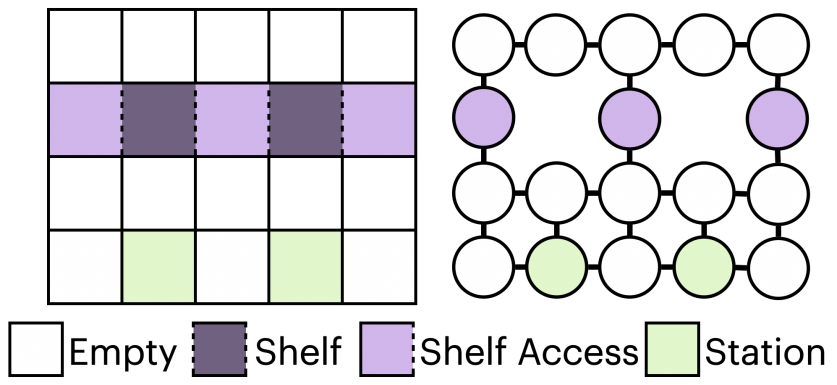
Fig. 1 (left) shows a warehouse with two shelves and two stations. Shelves are accessed from the east and west. Fig. 1 (right) shows the floorplan graph of this warehouse. If is the vertex in representing the cell at coordinates , this warehouse has shelf access vertices and stations . If the shelves at and contain units of product and , respectively, this warehouse has product vector and location matrix:
Products are carried by a team of mobile agents . Time in a warehouse is discretized. At each timestep , an agent has state , where and are the vertex that agent occupies and the product that it holds at time respectively. If agent is not holding a product at time , .
A timestep plan for a team of agents is a pair of matrices such that is the state of agent at time . A -timestep plan is feasible iff:
(1) An agent moves by 0 or 1 vertices per timestep, that is, the vertex that occupies at step is the same as or adjacent to the vertex that occupies at step :
(2) Two agents do not collide, that is, two agents do not occupy the same vertex or traverse the same edge in opposite directions at the same timestep:
(3) An agent can only pick up a product at a shelf access vertex containing and put down a product at a station. Let be the set of products accessible at vertex (if , ); then,
A workload is a vector where is the number of units of product which must be transferred to a station. We say that a timestep plan services workload iff it is feasible and it transfers units of each product to the warehouse’s stations .
Problem III.1 (Warehouse Servicing Problem)
Given a warehouse , a workload , and a timestep limit , find a timestep plan containing an arbitrary number of agents which services workload .
IV Co-Design Methodology
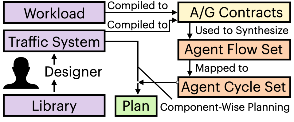
The structure of the methodology is shown in Fig. 2, providing a framework for designing a traffic system (Subsection IV-A). The framework offers rules for grouping the vertices in a warehouse floorplan graph into traffic system components. The high-level movement of agents through a traffic system is represented by an agent cycle set (Subsection IV-B). An agent cycle set is converted into a plan in a modular fashion (Subsection IV-C), such that, at each timestep, each component moves each agent it contains toward the next component in that agent’s agent cycle set.
The methodology finds an agent cycle set for a traffic system which services a workload within timesteps as follows. The properties of the flow of agents entering and leaving a component are compiled into an A/G contract. The properties that a traffic system’s set of agent flows must have to service workload within timesteps are also compiled into an A/G contract. An agent flow set satisfying the conjunction of these contracts is found (Subsection 3) and mapped to an agent cycle set (Subsection IV-E). By construction, the resulting agent cycle set is supported by the traffic system.
IV-A Traffic System Design Framework
An operator can construct a traffic system for a warehouse by dividing the vertices in its floorplan graph into disjoint simple paths called traffic system components. A component behaves similarly to a one way road. Agents enter a component at its head and exit it from its tail . A component may not contain both shelf access vertices and station access vertices. A component is termed a:
-
1.
shelving row if it contains shelf access vertices;
-
2.
station queue if it contains station vertices;
-
3.
transport if it contains neither.
Every station and shelf access vertex must be contained by a component. Other vertices, however, need not be. Vertices which are not part of any component are termed unused vertices since they will not be traversed by any agent.
A component has 1 or 2 inlet components and 1 or 2 outlet components . Agents must enter from one of its inlets and exit from one of its outlets. There must be an edge in the floorplan graph between the head of a component and the tail of each of its inlets and the tail of a component and the head of each of its outlets.
The connections between the components of a traffic system are represented by a directed graph termed a traffic system graph . Each vertex in is a component of the traffic system. There is an arc in iff component is one of component ’s inlets. A traffic system graph must be strongly connected, that is, there must be a path between any two components in a traffic system graph. Since every shelf access and station access vertex is in a component, it follows that there is a way for an agent to move from any shelf access vertex to any station access vertex and vice versa.
IV-B Agent Cycle Set
We synthesize a plan for a traffic system which satisfies a workload within timesteps from an agent cycle set . An agent cycle is a set of agents associated with a cycle of components in the traffic system graph . These components must include a target shelving row and a target station queue. The agents in an agent cycle transfer products from the target shelving row to the target station queue.
An agent cycle set has a cycle time . At timestep , each agent in an agent cycle is positioned on a unique component. Every timesteps, each agent in an agent cycle advances one component. Thus, an agent cycle delivers one product from its target shelving row to its target station queue every timesteps. In Subsection IV-C we show how we find a plan that realizes the agent movement specified by an agent cycle set. (Due to space constraints, we do not specify the exact timesteps at which an agent cycle picks up and drops off products at its target shelving row and target station queue.) In Subsection 3, we show how we find an agent cycle set that services a workload within timesteps.
IV-C Realizing an Agent Cycle Set
Let the time interval be divided into the cycle periods , , etc. Let be the number of vertices in a component and be the length of the longest component in a traffic system, i.e.,
The realization algorithm has the following property:
Property IV.1
Our realization algorithm can realize an agent cycle set if it has cycle time and there is no component contained by more than agent cycles.
The realization algorithm moves an agent at least once every other timestep until the agent advances to the next component in its agent cycle. It therefore takes at most timesteps for the realization algorithm to advance any agent in any agent cycle by one component. The realization algorithm assumes, however, that a component can send an agent to its outlets at least once every other timestep. This condition is violated if a component’s outlets fill up with agents, preventing them from accepting additional agents. To prevent a component from filling up, the realization algorithm prevents agents from advancing multiple components in a single cycle period. Since each component is in at most agent cycles, no more than unique agents will occupy any component every cycle period. Since , no component will ever fill up.
Realization Algorithm Initialization. At timestep , we place an agent associated with an agent cycle on an arbitrary vertex of each component that the agent cycle passes through.
Realization Algorithm Timestep. We realize the location of the agents in a traffic system at time from their locations at time by calling the function , Algorithm 1, on every component in the traffic system.
Let be the time at which the current cycle period starts (Line 1), be a list of the agents in at time ordered by their distance from , and be the agent at the head of this list (Line 2). If is at the head of and , the timestep when advanced to , was before , we check if can advance to the next component in its agent cycle (Line 3). We compute the index of the next component in from the index of the current component in (Line 4). If the component is accepting agents from , we move agent to this component’s tail (Lines 6-8). Next, we move agents within . Let be the vertex in following vertex , if one exists, and otherwise. We move each agent to vertex if it exists and is not occupied by another agent (Lines 9-14).
IV-D Synthesizing an Agent Flow Set
Let an agent flow be the number of agents that move from component to component carrying product every timestep period in a plan. Let an agent flow set be the set containing all of a plan’s agent flows:
An agent flow set completely describes how agents move between the components in a traffic system each cycle period. We synthesize an agent flow set which services workload within timesteps as follows.
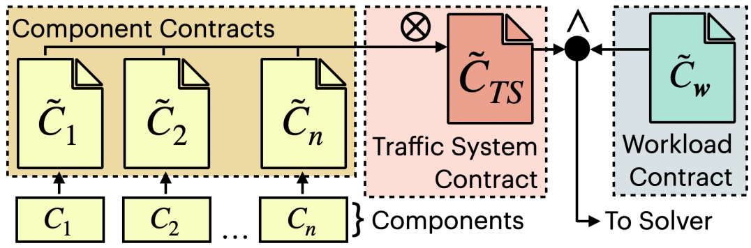
A component assumes that the agent flows entering it have certain properties and guarantees that the agent flows leaving it have certain properties. These assumptions and guarantees are compiled into an A/G contract , termed a component contract (Fig. 3, yellow). Component contracts are composed into a traffic system contract (Fig. 3, red) describing the agent flow sets that the traffic system allows, i.e.,
The properties that a traffic system’s agent flow set must have to service workload within timesteps are compiled into an A/G contract termed a workload contract (Fig. 3, blue). We attempt to synthesize an agent flow set which satisfies the conjunction of the traffic system contract and workload contract (Fig. 3). If no such agent flow set exists, a plan which services workload within timesteps cannot be synthesized using our methodology.
Component Contract Assumptions. As discussed in Subsection IV-C, at most agents may enter any component in any cycle period, i.e.,
Since a flow is defined as a non-negative integer, the minimum flow entering any component is 0.
Component Contract Guarantees. Let be the number of units of product transferred from an agent to a station in component each cycle period. If component does not contain a station, . If component contains stations, is between 0 and the number of agents entering component carrying each cycle period, that is,
Let be the number of units of product transferred from a shelf in component each cycle period. If component does not contain shelves, . If component contains shelves, is limited by the number of units of product that component contains. Let be the total number of units of product available at :
Let be the number of cycle periods executable in timesteps. In cycle periods, a component can transfer at most units of product each cycle period. It follows that:
A product can only be transferred to an unburdened agent. Thus, the total number of products transferred to agents in each cycle period is limited by the total number of unburdened agents entering each cycle period.
Agents cannot appear or disappear. Thus, the total flow of agents carrying product out of component is:
-
1.
the total flow of agents carrying product into ,
-
2.
plus the total number of unburdened agents given a unit of product from a shelf in each cycle period,
-
3.
minus the total number of agents which transfer a unit of product to a station in each cycle period. Overall,
An analogous expression can be written relating the total flow of unburdened agents leaving and entering a component :
Workload Contract. A workload contract makes no assumptions. It guarantees that the total number of units of product transferred to the warehouse’s stations each cycle period is greater than , where is the demand for in workload and is the number of cycle periods executable in timesteps, i.e.,
The above contracts (and associated constraints) are used to generate a formula in propositional logic augmented with arithmetic constraints over the reals, which is solved using a satisfiability modulo theory (SMT) solver to produce the flow rate through every component for every product.
IV-E Mapping the Agent Flow Set to an Agent Cycle Set
By construction, an agent flow set has the properties:
Property IV.2
There is a set of paths on for each product such that:
-
1.
There are exactly paths in beginning at each component .
-
2.
There are exactly paths in ending at each component .
-
3.
There are exactly paths that contain the edge for each edge .
Property IV.3
There is a set of paths on such that:
-
1.
There are exactly paths in beginning at each component .
-
2.
There are exactly paths in ending at each component .
-
3.
There are exactly paths that contain the edge for each edge .
Properties IV.2 and IV.3 imply that there is a bijection for any agent flow set such that if path is mapped to path , then the head of path is the tail of path and vice versa:
An agent cycle set is then formed from an agent flow set by turning each pair of paths in the bijection into a cycle.
V Evaluations
The proposed methodology is implemented as an automatic toolchain. The component and workload contracts are compiled and composed using the CHASE framework [8]. An agent flow set satisfying these contracts is then found using Z3 [9]. All other toolchain components are implemented in Python 3.9. The methodology is evaluated on two real industrial scenarios taken from the literature: a Kiva (now Amazon Robotics) fulfillment center [10] and a package sorting center [11].
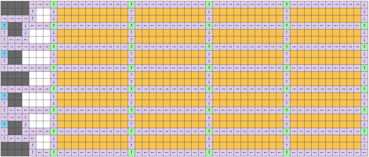
Fulfillment Center. A fulfillment center ships products to individual consumers. A fulfillment center map is characterized by blocks of shelves in its center and stations on its perimeter. The proposed approach is evaluated on two fulfillment center maps, a real map borrowed from [10] with 1071 cells, 560 shelves, 4 stations, and 55 unique products and a synthetic map based on [10] with 793 cells, 240 shelves, 1 station, and 120 products. The real fulfillment center map is depicted in Fig. 4. Shelves are depicted as yellow cells, stations as blue shelves, obstacles as grey cells and empty space as white cells. The tail of each component is depicted as a green cell with an exclamation mark. Every other vertex in a component is depicted as a purple cell with an arrow pointing to the next vertex in the component.
Sorting Center. The methodology is also evaluated on a variant of the WSP which takes place in a sorting center [11]. A sorting center sorts packages by destination. A sorting center map is characterized by uniformly placed chutes in its center and bins of unsorted packages on its perimeter. Each chute leads to a shipping counter bound for a unique destination. An agent sorts a package by ferrying it from a bin to the chute associated with its destination. Typically, a bin is modeled as having an unlimited number of packages. The goal is to fill each shipping container before it is scheduled to depart.
This problem is modeled as an WSP instance as follows. Let the th chute be modeled as a shelf containing an arbitrary amount of the product . Let each bin of unsorted products be modeled as a station. Let be the number of packages that must be brought to the th chute. An instance of the WSP is generated where the demand for product is . Solving this WSP instance produces an agent cycle set where units of product are brought from the th chute to the bins of unsorted products. Swapping the locations where agents pick up and drop off products generates the desired solution.
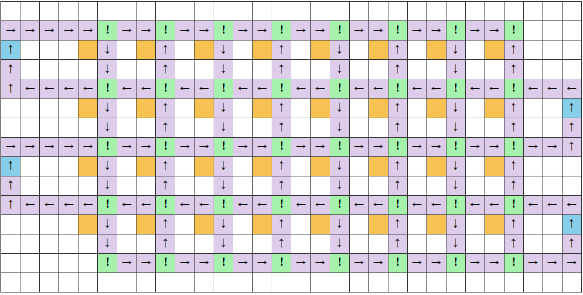
The sorting center evaluation is conducted on a map based on [11]. This map contains 406 cells, 32 chutes and, 4 bins. It is depicted in Fig. 5.
Experimental Hardware. Each evaluation was performed on an 2.6 GHz Intel(R) Core i7-10705H CPU with 32 GB of RAM in a Ubuntu 20.04 VM run on Windows 11.
| Map | Unique Products | Units Moved | Runtime (s) |
|---|---|---|---|
| 36 | 160 | 8.054 | |
| Sorting Center | 36 | 320 | 8.343 |
| 36 | 480 | 14.437 | |
| 55 | 550 | 6.939 | |
| Fulfillment 1 | 55 | 825 | 7.001 |
| 55 | 1100 | 8.014 | |
| 120 | 1200 | 65.880 | |
| Fulfillment 2 | 120 | 1320 | 65.886 |
| 120 | 1440 | 67.825 |
Results. The three WSP instances were generated on each map. For each WSP instance, Table I lists:
-
1.
the number of unique products placed in the warehouse.
-
2.
the total units of product moved to a station.
-
3.
the time required to generate an agent flow set (the time required to convert an agent flow set into a plan is small).
The length of a plan for each WSP instance was limited to 3,600 timesteps. Solver runtime was limited to 1 hour.
The proposed methodology was able to solve an WSP instance where more than 1400 products had to be moved to a station in just over a minute. We benchmarked the methodology on this instance against Iterated EECBS [4], a state-of-the-art search-based lifelong path planner as follows. Iterated EECBS was given the start position of each agent in our solution. It was asked to find a plan where each agent visited the same sequence of shelves and stations as it did in our solution. Iterated EECBS failed to terminate after an hour.
The runtime of traditional multi-agent path planners is exponential to the size of their team of agents, the number of locations that an agent has to visit, and the average distance between the locations that an agent has to visit. Our proposed methodology, by contrast, is exponential in the number of components in the traffic system (finding a set of agent flows is reducible to the Integer Linear Programming problem). As a result, our methodology outscales state-of-the-art path planners. Additionally, our methodology is relatively insensitive to the number of products in a WSP instance. On both the sorting center and fulfillment center, doubling the units of product in the workload increased runtime by less than 10%.
VI Conclusion
In this paper we introduce the first methodology for solving the warehouse servicing problem. This methodology provides a designer with a formal framework for designing a warehouse traffic system. The traffic flows that each component can support are captured using contracts. Combining these contracts with a contract capturing the traffic flow that a workload for a warehouse requires allows us to synthesize a traffic flow satisfying a given WSP instance. A simple deterministic algorithm is used to convert this traffic flow into a plan for discrete agents. The proposed methodology is evaluated on maps taken from real automated warehouses and shown to be able to solve WSP instances on these maps involving more than a thousand products in just over a minute. In future work, we hope to find a bounded-suboptimal solution to the WSP. In particular, we intend to look at ways to iteratively refine our feasible solution into an optimal solution.
References
- [1] E. Ackerman, “Amazon Uses 800 Robots to Run This Warehouse,” https://spectrum.ieee.org/amazon-introduces-two-new-warehouse-robots, IEEE Spectrum, 2021, accessed: 16-May-2022.
- [2] J. D. Ullman, “NP-Complete Scheduling Problems,” Journal of Computer and System Sciences, vol. 10, no. 3, pp. 384–393, 1975.
- [3] M. Liu, H. Ma, J. Li, and S. Koenig, “Task and Path Planning for Multi-Agent Pickup and Delivery.” in Proc. of the International Joint Conference on Autonomous Agents and Multiagent Systems Search, 2019, pp. 11 560–11 565.
- [4] J. Li, W. Ruml, and S. Koenig, “EECBS: A Bounded-Suboptimal Search for Multi-Agent Path Finding,” Proc. of the AAAI Conference on Artificial Intelligence, vol. 35, pp. 12 353–12 362, 2021.
- [5] H. Ma, W. Honig, T. K. Satish, N. Ayanian, and S. Koenig, “Lifelong Path Planning with Kinematic Constraints for Multi-Agent Pickup and Delivery.” in Proc. of the AAAI Conference on Artificial Intelligence, 2019, p. 7651–7658.
- [6] X. Wu, Y. Liu, X. Tang, W. Cau, F. Bai, G. Khonstantine, and G. Zhao, “Multi-Agent Pickup and Delivery with Task Deadlines.” in Proc. of the International Symposium on Combinatorial Search, 2021, p. 206–208.
- [7] A. Benveniste, B. Caillaud, D. Nickovic, R. Passerone, J.-B. Raclet, P. Reinkemeier, A. Sangiovanni-Vincentelli, W. Damm, T. A. Henzinger, K. G. Larsen et al., “Contracts for System Design,” Foundations and Trends in Electronic Design Automation, vol. 12, pp. 124–400, 2018.
- [8] P. Nuzzo, M. Lora, Y. A. Feldman, and A. L. Sangiovanni-Vincentelli, “CHASE: Contract-based Requirement Engineering for Cyber-Physical System Design,” in Proc. of the 2018 Design, Automation & Test in Europe Conference & Exhibition (DATE). IEEE, 2018, pp. 839–844.
- [9] L. d. Moura and N. Bjørner, “Z3: An efficient SMT solver,” in Proc. of the International conference on Tools and Algorithms for the Construction and Analysis of Systems. Springer, 2008, pp. 337–340.
- [10] P. R. Wurman, R. D’Andrea, and M. Mountz, “Co-ordinating Hundreds of Cooperative, Autonomous Vehicles in Warehouses,” in Proc. of the AAAI Conference on Artificial Intelligence, 2007, p. 1752–1760.
- [11] Q. Wan, C. Gu, S. Sun, M. Chen, H. Huang, and X. Jia, “Lifelong Multi-Agent Path Finding in a Dynamic Environment,” in The International Conference on Control, Automation, Robotics and Vision, 2018, p. 875–882.