Rashba spin-orbit coupling enhanced magnetoresistance in junctions with one ferromagnet
Abstract
We explain how Rashba spin-orbit coupling (SOC) in a two-dimensional electron gas (2DEG), or in a conventional -wave superconductor, can lead to a large magnetoresistance even with one ferromagnet. However, such enhanced magnetoresistance is not generic and can be nonmonotonic and change its sign with Rashba SOC. For an in-plane rotation of magnetization, it is typically negligibly small for a 2DEG and depends on the perfect transmission which emerges from a spin-parity-time symmetry of the scattering states, while this symmetry is generally absent from the Hamiltonian of the system. The key difference from considering the normal-state magnetoresistance is the presence of the spin-dependent Andreev reflection at superconducting interfaces. In the fabricated junctions of quasi-2D van der Waals ferromagnets with conventional -wave superconductors (Fe0.29TaS2/NbN) we find another example of enhanced magnetoresistance where the presence of Rashba SOC reduces the effective interfacial strength and is responsible for an equal-spin Andreev reflection. The observed nonmonotonic trend in the out-of-plane magnetoresistance with the interfacial barrier is an evidence for the proximity-induced equal-spin-triplet superconductivity.
I I. Introduction
The magnetoresistance (MR) is a key figure of merit in spintronics and its enhancement is associated with the major advances in magnetically sensing and storing information Maekawa and Gafvert (1982); Moodera et al. (1995); Žutić et al. (2004); Parkin et al. (2004); Tsymbal and Žutić (2019). Typically, a large MR is sought in structures with multiple ferromagnetic regions, where the resulting spin-valve effect implies that the resistance of the systems depends of the relative magnetization, M orientation of those ferromagnets.
However, as first discovered in 1857 by Lord Kelvin Thomson (1857), anisotropic MR (AMR) shows that with spin-orbit coupling (SOC) there is a change of the electrical resistivity with the relative direction of the charge current with respect to M of a single bulk ferromagnet (F), such as Ni or Fe. Another example of MR with a single F region is the tunneling AMR (TAMR) Gould et al. (2004); Moser et al. (2007); Chantis et al. (2007); Fabian et al. (2007), also a manifestation of the interplay between SOC and M. Unfortunately, while a single F region simplify scaled-down devices both AMR and TAMR are limited by their small magnitudes (typically for in-plane M rotation) Shen et al. (2020); Fabian et al. (2007).
In this work we explore a possibility for a much larger MR with a single F region and Bychkov-Rashba, also known as Rashba SOC Bychkov and Rashba (1984), in both normal and superconducting state. The resulting enhanced MR is not only significant for the potential spintronic applications, but could also distinguish between the trivial and topological states Shen et al. (2020), or provide a signature of equal-spin-triplet superconductivity, sought to realize coexistence of ferromagnetism and superconductivity, dissipationless spin currents, and Majorana bound states for fault-tolerant topological quantum computing Cai et al. (2023); Amudsen et al. (2022); Eschrig (2015); Linder and Robinson (2015); Buzdin (2005); Bergeret et al. (2005); Kitaev (2001); Aasen et al. (2016); Güngördü and Kovalev (2022); Laubscher and Klinovaja (2021).
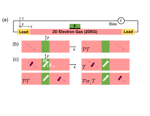
To realize an enhanced normal-state MR, we consider a lateral geometry from Fig. 1(a). The resulting TAMR is not determined by highly spin-polarized carriers or a large exchange energy in the F region, but by the high interfacial transmission from the interplay of the Rashba SOC, the barrier strength at the F/2DEG interface, and the proximity-induced exchange field, which can reach tens of meV and extend over tens of nm Žutić et al. (2019); Akimov et al. (2017); Korenev et al. (2019); Takiguchi et al. (2019); Betthausen et al. (2012).
For a simple spinless case of a square barrier with thickness and height , a standard expression for transmission, , with energy, , is Griffiths (2005); Sakurai and Napolitano (2011)
| (1) |
where is the wave vector. The perfect transmission, , requires (i) or (ii) , where , gives the resonance condition. This well-known behavior Griffiths (2005); Sakurai and Napolitano (2011) is usually not connected to the parity-time symmetry , depicted in Fig. 1(b), which satisfies both cases (i) and (ii). Such a symmetry, where is the parity operator, is the time-reversal operator, and is the complex conjugation operator, which ensures that the incoming and transmitted spinless wave are identical, up to a phase.
However, generalization of the perfect transmission for spin-1/2 carriers, where , and is the Pauli matrix, is much less explored with SOC and magnetic barriers. It was recently found that the perfect transmission emerges when the eigenstates of the F/2DEG Hamiltonian, , satisfy , the spin-parity-time symmetry, where [, ] Shen et al. (2020). Intuitively, the emerging perfect transmission for the eigenstates of which satisfy can be understood from Fig. 1(c). reverses the spin and motion of the incident wave, while inverts both the spin (through ) and position (through ) of the wave. By applying the operator the incident wave on the left is transformed to itself, but as a transmitted wave on the right. Therefore, scattering states which are eigenfunctions of experience perfect transmission. The resulting in-plane TAMR amplitude
| (2) |
where the -dependent conductance is the inverse of the resistance, , with defined in Fig. 1(c), can be enhanced by one or two orders of magnitude.
To study an enhanced out-of-plane MR in the superconducting state, we focus on the recent transport experiments in junctions of quasi-2D van der Waals F with conventional -wave superconductors (S) (Fe0.29TaS2/NbN) Cai et al. (2021). Compared to the normal state MR, the key difference is the presence of Andreev reflection at the F/S interface with Rashba SOC. In this process an incoming electron is reflected as a hole and the Cooper pair enters the S region. With SOC, in addition to the conventional Andreev reflection, where the incoming and reflected particle have an opposite spin, a spin-flip or equal-spin Andreev reflection is also possible in which the incoming and reflected particles have the same spin Žutić and Das Sarma (1999); Högl et al. (2015). While the first process is responsible for the spin-singlet proximity-induced superconductivity, the second yields the spin-triplet counterpart.
The corresponding anisotropic behavior, magnetoanisotropic Andreev reflection (MAAR) can be viewed as the generalization of TAMR Högl et al. (2015); Vezin et al. (2020); Lv et al. (2018), which is recovered in the normal state of the F/S junction for a large bias, , applied magnetic field, , or a high temperature. From a full MAAR calculation for the F/S junction, such a TAMR value can be obtained by taking the superconducting gap to vanish. Similar to Eq. (2), the out-of-plane MAAR amplitude in F/S junctions is
| (3) |
where is the angle defined in Fig. 2. As we later show, F/S measurements for the MAAR can be orders of magnitude larger than TAMR in the normal state. This enhancement is dominated by the spin-flip Andreev reflection with Rashba SOC at the F/S interface.
Despite the different geometries for the considered F/2DEG and F/S structures, which also differ by the in-plane vs out-of-plane rotation of M, we find important common features and surprising nonmonotonic trends in TAMR in both systems. Some of these identified trends arise from the role of Rashba SOC which modifies the effective barrier strength and determines the condition for perfect transmission or an enhanced contribution of the spin-flip Andreev reflection.
Following this Introduction, we explore the structures from Fig. 1(a). In Sec. II we describe the F/2DEG Hamiltonian, consider the influence of SOC on the scattering states and analyze the conductance which reveals different resonant-like behavior, peaked at different parameters. The calculation of in-plane TAMR in Sec. III reveals different trends as a function of the barrier and SOC strengths as well as the proximity-induced exchange splitting. In Sec. IV we examine the superconducting structures from Fig. 2 and describe the corresponding F/S Hamiltonian, followed by the measured and calculated conductance using a simple F/S Hamiltonian. In Sec. V we describe how the predicted influence of the Rashba SOC on the effective barrier strength provides a good description of the measured out-of-plane MR and confirms the evidence for the equal-spin-triplet superconductivity in the considered heterostructures. In Sec. VI we provide additional discussion for the relevance of enhanced MR in the normal and superconducting state and note some open questions for future work.
II II. F/2DEG HAMILTONIAN AND CONDUCTANCE ANALYSIS
To explore the interplay of the proximity-modified 2DEG and SOC, together with the magnetic anisotropy of the transport properties, we consider a model Hamiltonian of the system represented in Fig. 1(a) given by
| (4) |
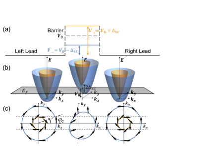
where is the effective mass, is the Rashba SOC strength, is the unit vector along the -axis, is the 2D momentum operator, is the vector of Pauli matrices, describes the potential barrier, and are the magnitude and direction of the proximity-induced ferromagnetic exchange field. The function describes a square barrier of thickness . We focus on electrons, not holes Winkler (2003); Rozhansky et al. (2016); Liu et al. (2018); Arovas and Lyanda-Geller (1998), with the effective barrier region and typical band structure shown in Fig. 3. In Fig. 3(a) the resulting spin-dependent barrier is shown in a weak SOC limit, , where is the Fermi wave vector averaged over the inner and outer contours in the leads, while is the Fermi energy. The blue (yellow) contours in Fig. 3(c) denote lower (upper) bands. Inside the barrier the upper band is irrelevant since its bottom is above . The spin orientations are marked by arrows.
Due to Rashba SOC, the wave functions can be classified by the helicity index, where refers to the inner (outer) Fermi contour as depicted in Fig. 3(c). The scattering states for the finite square barrier model can be written as , with sample area and the conserved parallel component of the wave vector in the ballistic transport. Right from the barrier, is a combination of the two plane waves with transmission coefficient, and , where , to describe intraband and interband scattering processes.
By matching and in the regions, , , and , we obtain , , and the particle current density of the channel
| (5) |
here, the group velocity of the scattered particle, , has the same magnitude for the two bands. This current contains contributions from the intra- and inter-channel transmission, where is the incident and the propagation angle of the cross-channel wave with the conservation of the component and is related to by , where
| (6) |
In the low-bias limit, i.e. , we get the expression for the conductance in the channel Girvin and Yang (2019)
| (7) |
where is the sample width, the -channel Fermi wave vector [ in Eq. (6)] and the transmission is
| (8) |
The total conductance is the sum of the two channels,
| (9) |
To explore the evolution of the conductance as a function of the proximity-induced field and its direction, we consider its normalized value in Eq. (9) expressed in terms of the Sharvin conductance for the 2DEG system
| (10) |
As shown in Fig. 1(c), the symmetry leads to perfect transmission and influences the conductance for the 2DEG system. Specifically, scattering states which satisfy , with eigenvalues of the form , include the perfect transmission either due to effectively vanishing barrier or the resonances expected from the standing-wave condition. However, symmetry is not an intrinsic symmetry of the system and does not commute with in Eq. (4). Instead, the symmetry emerges only for certain specific system parameters and scattering states satisfying,
| (11) |
where the index emphasizes that the relation is restricted only to the cases of the perfect transmission (for vanishing of the effective barrier or at resonances). This symmetry generalizes a simple case of the perfect transmission in a potential barrier (or a spinless) system Griffiths (2005).
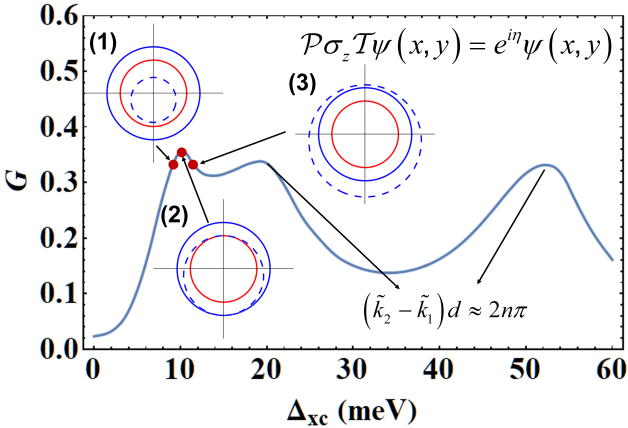
To understand the relation between conductance, barrier parameters, and the perfect transmission, we perform a Fermi contour analysis illustrated in Fig. 4. In the spinless case, with the better matching between Fermi contours in the lead and barrier a higher transmission is expected. For a simple 1D geometry (normal incidence or a fixed ) and -barrier, the transmission is Blonder et al. (1982)
| (12) |
where is the effective barrier strength which combines the influence of a native barrier and the Fermi wave vectors mismatch in the two regions Žutić and Das Sarma (1999); Vezin et al. (2020); Blonder and Tinkham (1983); Žutić and Valls (2000). Since the difference between the lead and barrier Fermi contours is associated with the effective barrier potential, a larger mismatch between Fermi contours corresponds to a larger effective and thus to a lower transmission.
We now generalize this situation to a spin-dependent case in the presence of and , as depicted in Figs. 3(b) and (c). The effective barrier at the F/2DEG interface becomes spin-dependent since the energy bands in the barrier are split by the exchange field and spinless becomes Vezin et al. (2020). For the situation from Fig. 3, we can decompose the incident spinor in the basis constructed by the corresponding barrier eigenspinor ( is the same as in the incident state) for the lower band and its antiparallel partner from the upper band , i.e., . The first term undergoes a weak effective barrier while the second term experiences a strong barrrier .
The effective interfacial barrier is inequivalent for two helicities (for outer/inner Fermi contours) leading to an important influence of spin mismatch on transmission, not just the mismatch of the Fermi contours Vezin et al. (2020). Considering that the direction of the proximity-induced exchange field, [see Eq. (4)] is determined by , for an in-plane as depicted in Fig. 1(c), the effective barrier for from the outer band of the lead is
| (13) |
Equivalently, for from the inner band of the lead
| (14) |
In Eqs. (13) and (14) the impact of the reflected states is neglected, and this treatment is most accurate for small effective , i.e., for a good matching of Fermi contours. We note that the effective barrier becomes energy-dependent when and , opening the possibility for resonant tunneling to occur when the energy of the incident carrier is such that (or ).
Due to the spin mismatch, we need to include a correction of in the transmission, i.e., , where is the transmission without the spin mismatch. We can see from Fig. 1(c) that the spin mismatch is much smaller for the incident state from the outer lead band , i.e., , which indicates that the most of is contributed by the incident states from the outer lead band. When the state inside the barrier is the same (up to a phase) as that in the lead, perfect transmission is achieved.
With vanishing Rashba SOC, , outer and inner lead Fermi contours coincide and the spin-dependent barrier, , from Fig. 3(a) is recovered. We focus on , leads to the perfect transmission, , from our discussion above. From Eqs. (13) and (14), , so one can still get when . We will further address the importance of vanishing in F/S junctions. At a fixed , the eigenstate for the perfect transmission , precisely satisfies the symmetry: , with eigenvalue and an arbitrary phase .
This analysis and the relevance of the symmetry can be applied to Fig. 4 with parameters of a typical InGaAs/InAlAs 2DEG, , where is the free-electron mass, and eVÅ Nikolić et al. (2005). It is crucial to note that symmetry arguments for a perfect transmission pertain to a single (single channel), while the geometry from Figs. 1(a) and 3 corresponds to a 2D system where the total reflects the contribution from all allowed . In the spinless case, maximizing means an overall contour matching, while even with adding spin our Fermi contour analysis provide a valuable tool to visualize and understand various trends in .
With conserved , from Fig. 3(c) we can recognize many similarities with the Snell’s law Žutić and Valls (2000). We may get propagating or decaying (evanescent) states in different regions, depending on the incident angle, and the particular contour (outer, inner) considered. For example, for carriers from the band (outer contour) and incident angles exceeding the critical angle,
| (15) |
where is given by Eq. (6), the transmission and reflection to the band are not allowed because there are no such propagating states. In this regime, back scattering is suppressed while is enhanced.
The overall maximum in is related to the perfect transmission due to the Fermi contour matching depicted by the example (2) in Fig. 4. As shown for examples (1) and (3) a small change in leads to worse Fermi contour matching and reduced . The origin of the overall peak in near can be further understood in the small SOC limit. The barrier contour reduces to a shifted circle with radius , where we recall that is average of the outer and inner lead circles. The barrier contour can then be approximated by
| (16) |
In the region near the , both and , which correspond to and , reach their maxima because of the best matching of Fermi contours between lead and barrier. The shift of barrier circle is always to and is of the first order in , while the deformation is a higher-order correction.
Remarkably, the other local maxima in , for larger in Fig. 4, also satisfy the symmetry. However, instead of the contour matching, they are due to standing de Broglie waves in the barrier and the constructive interference. With outer/inner lead contours, there are four eigenstates in the leads with , we can distinguish cases: (i) 4 (4), (ii) 4 (2), (iii) 2 (4), and (iv) 2 (2) propagating states in the leads (barrier) Shen et al. (2020).
In cases (i) and (ii) [arising for an incident state from the inner band of for the outer band and ], the perfect transmission means that no reflected wave should exist in the left lead, while the state in the right lead should match, up to a phase, the corresponding one in the left lead. For case (i), under symmetry operation, up to a phase, all the propagating states inside the barrier, with component of the wave vector, , j=1,…,4, remain the same. By matching and , as noted in Sec. II, the resonance condition is satisfied when
| (17) |
where However, for the system we consider, and Eq. (17) only holds in few special cases.
In case (ii) the resonance condition similar to Eq. (17) is not possible, unless for the normal incidence when . In that case, the coefficients of the decaying barrier states vanish and the spins of all scattering states become parallel to each other which makes the system “spinless” and perfect transmission becomes possible.
In cases (iii) and (iv), the presence of the decaying states in the leads can be understood for the incident particle from the band at an angle . Since such decaying states in the leads do not carry any current Žutić and Valls (2000), as can be understood from the Snell’s law, the perfect transmission and the resonance conditions are still possible. In case (iv), under the symmetry operation, up to a phase, the two propagating states inside the barrier remain the same, while the two decaying states in the barrier become, up to a phase, the two decaying states in the leads. The resonance condition is
| (18) |
where for the component of the propagating wave vectors in the barrier we assume , while the correction . Since the resonances occur at , the magnitude of the propagating barrier wave vector is much larger than . Therefore, the component of the propagating barrier wave vector is almost the same for all the incoming states with different incident angles, which means the transmission resonances occur for all the incoming states almost simultaneously when the resonance condition is satisfied and thus the maximum is reached.
The two local maxima in near meV and 55 meV, shown in Fig. 4, both correspond to the case (iv) and a large regime, where for the propagating wave vectors are . Applying the resonance condition from Eq. (18) the first (second) of these maxima corresponds to (). However, with large , the correction in Eq. (18) is very small such that the resonance condition is accurately described by the spinless case where .
III III. F/2DEG In-Plane TAMR
A large value of TAMR, as defined in Eq. (2), has the origin in the difference for the maximum and , that is for the and orientations. In Fig. (4), for and shown examples (1)-(3), we see the expected barrier Fermi contour (broken line) shifted downward (). This broken symmetry leads to an unusual tunneling planar Hall effect, where the transverse voltage is maximum for the , while other Hall effects would vanish Scharf et al. (2016). Due to the same asymmetry, the perfect match for both upper and lower half of the circle cannot be achieved simultaneously. We see in examples (1)-(3) that the upper (lower) half of the barrier contour tends to match the inner (outer) lead contour since the spin mismatch is smaller for these states. The best possible simultaneous match of Fermi contours yields the large transmission at , resulting in the first peak in , even for large when the barrier contour is strongly deformed from a circle, as in Fig. 3(c).
As we see from Fig. 4 with multiple peaks in , there also exist several resonances which could influence the TAMR. In the limit of , the condition for such resonances can be derived from Eq. (18) with
| (19) |
for both and which correspond to and , where describes the order of the resonance that pertains to the case (iv) in Sec. II. In this situation, of vanishing Rashba SOC, the conductance no longer depends on the in-plane and we expect a vanishing TAMR, as inferred from Eq. (2).
However, already for a small and nonvanishing the maximum is achieved for a different condition when the barrier circle shares the same size as the outer circle of the lead Shen et al. (2020). Up to the first order in the condition leading to the maximum is given by . When such a condition is satisfied, the barrier Fermi contour matches the outer lead contour instead of the inner one, because the main contribution is from the incident particles on the outer Fermi contour. Correspondingly, near , due to contour matching and the perfect transmission, we expect enhanced TAMR, as can be seen from Fig. 5.
Furthermore, when , , which determine the resonance condition in Eq. (18), varies as is rotated. This means the maxima for and will be achieved at different . Therefore, similar to the situation near , an enhanced TAMR will arise from the small difference in the peak conditions. With fixed and , up to the lowest-order correction of , we can derive the difference in at the same order maxima () of and
| (20) |
Unlike the perfect transmission condition due to contour matching, the difference in now quadratic in .
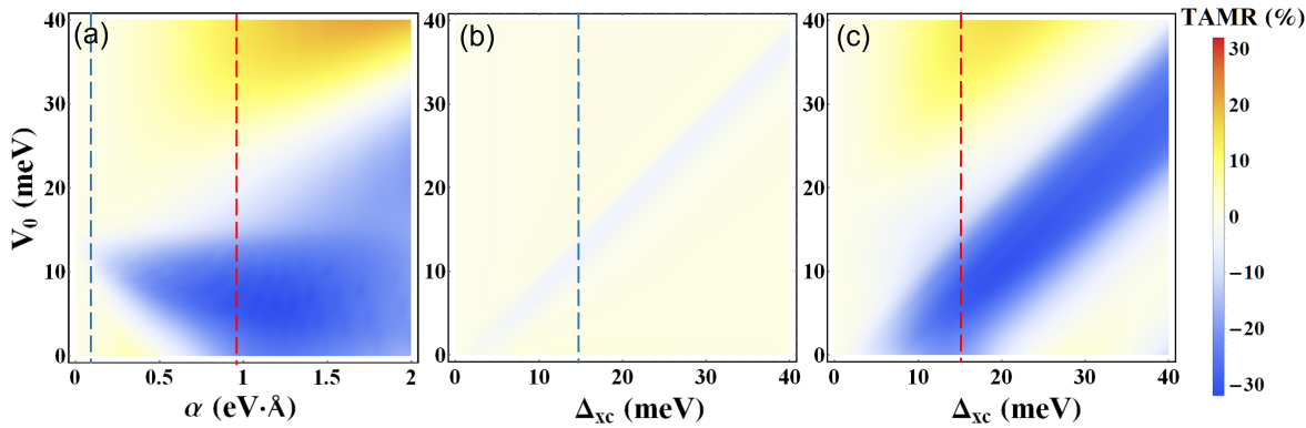
With this conductance analysis and nonmonotonic in Fig. 4, a consequence of the collective contributions of multiple states corresponding to different propagation directions of the tunneling carriers, we expect various nonmonotonic TAMR trends and a strong influence of Rashba SOC. We can see from Fig. 5(a) that increasing can enhance both TAMR and the range of for such enhancement. However, if gets too large (eVÅ), the absolute value of TAMR decreases, for a large range of .
The reason for this unexpected trend in TAMR() can be understood from calculated results in Figs. (5)(b) and (c), which are shown for two different values of , as indicated by blue and red vertical lines in Fig. (5)(a). From the previous discussion of a small limit, we know that peaks near and such a peak will be shifted by when is rotated. The sensitive dependence of on the orientation leads to a large TAMR near the diagonal line in the parameter space, shown in Figs. (5)(b) and (c). Since such a shift is proportional to , by comparing Figs. (5)(b) and (c) there is a wider range of the enhanced TAMR for a larger .
However, if is too large (compared to and ), the impact of the orientation becomes negligible, and TAMR starts to decrease. This can be seen at the lower-left corner in Fig. (5(c), where the resonant TAMR is much smaller when both , . Even for a fixed , for example at 5 meV, we see that with the absolute value of TAMR is nonmonotonic and TAMR also changes sign.
The calculated in-plane TAMR reveals various other peculiar trends. For a fixed [Fig. (5(a)] or [Fig. (5(b) and (c)], we can see that TAMR can be nonmonotonic in and even change its sign. Furthermore, there is as a clear nonmonotonic amplitude with at a fixed in Fig. (5(b). Different barrier thickness in Fig. 5 (26 nm) from that in Fig. 4 (13 nm) modify the respective values for the perfect transmission. These different TAMR trends in Fig. 5 were primarily related to the best contour matching, near [as the first peak in , seen in Fig. 4)], while the role of resonance can be seen in the lower-right corner in Fig. 5(c).
From the angular dependence of TAMR, it is possible to obtain valuable information about the interfacial crystallographic symmetry Žutić et al. (2019). For a 2DEG system, in the limit and , the leading contribution to the in-plane angular dependence of from the two incoming channels with helicity , is . However, with their opposite signs, these leading contributions cancel in the total , which becomes significantly smaller, quadratic in the small parameter, and has a different angular dependence, resulting in
| (21) |
While this angular dependence also coincides with the results from the surface states of 3D topological insulators, their junctions with ferromagnets do not have a resonant TAMR behavior of a 2DEG and thus lead to different trends in and Shen et al. (2020).
Another striking signature of the underlying resonant behavior of the calculated TAMR is its magnitude. In commonly considered vertical tunneling devices, the in-plane TAMR is rather small (typically %) even for large carrier spin polarization Gould et al. (2004) and exchange energies eV Moser et al. (2007); Park et al. (2008); Uemura et al. (2009). In contrast, with much smaller proximity-induced exchange fields, meV, we find a much larger TAMR in our lateral (planar) structures, % even for SOC for a typical InAs-based 2DEG.
As we next focus on the F/S junctions and their superconducting out-of-plane TAMR analog [recall Eq. (3)], we will see that some
of the calculated nonomonotonic trends, similar to those we discussed for F/2DEG systems, are experimentally verified, while the
analysis of effective barriers allows us to give simple estimates of the enhanced MR which can even reach 100 % in the measured samples.
IV IV. F/S HAMILTONIAN AND CONDUCTANCE
Motivated by the recent experiments demonstrating a large MR enhancement in F/S junctions Cai et al. (2021), depicted in Fig. 2, we consider a simple model for F/S Hamiltonian, . It shares several similarities with in Eq. (4), used to analyze in-plane TAMR. The key difference in the superconducting state is the need to simultaneously include the presence of electrons and holes and the pair potential , which couples electronlike and holelike components of the underlying wavefunction.
Additionally, while Rashba SOC was inherent for whole 2DEG region, in F/S junction it is only an interfacial contribution, along with the potential barrier, between F and S region. Now we study vertical transport and out-of-plane MR [recall Eq. (3)], which is dominated by the process of Andreev reflection, introduced in Sec. I and it is the microscopic mechanism for the superconducting proximity effects Žutić et al. (2019).
Before specifying and the resulting equation for quasiparticle states, it is instructive to note a similarity between the two-component transport in normal metal (N)/S junctions (for electronlike and holelike quasiparticles) and F/N junctions (for spin , ), which both lead to current conversion, accompanied by additional boundary resistance Žutić et al. (2004). In the N/S junction Andreev reflection is responsible for the conversion between the normal and the supercurrent, characterized by the superconducting coherence length, while in the F/N case a conversion between spin-polarized and unpolarized current is characterized by the spin diffusion length. In the N/S charge transport, , which couples electronlike and holelike states, plays a similar role of the spin-flip potential which couples , states in the F/N spin transport.
We consider ballistic F/S junction, depicted in Fig. 2, having a flat interface at with potential and Rashba SOC scattering. Similar to the approach in Sec. II of matching the wavefunctions for the scattering states in different regions, we generalize the Griffin-Demers-Blonder-Tinkham-Klapwijk formalismGriffin and Demers (1971); Blonder et al. (1982); Kashiwaya and Tanaka (2000); Wu and Samokhin (2009) to solve Bogoliubov-de Gennes equation for quasiparticle states , with energy Högl et al. (2015), where
| (22) |
with the -wave pair potential which, for a homogeneous S region, is also the value of the superconducting gap, and the single-particle Hamiltonian for electrons is
| (23) |
while for holes . In Eq. (22) is the effective mass and is the chemical potential. The interfacial scattering is modeled by delta-like potential barrier, with the effective barrier height and width and the interfacial Rashba SOC of strength has different units than Rashba SOC in F/2DEG Moser et al. (2007)
| (24) |
As in Sec. II, is the exchange spin splitting and we denote the orientation of the magnetization, , by , but we now also consider its out-of-plane rotation .
Since the in-plane wave vector is conserved, the scattering states for incident spin electron are given by in a four-component basis, they include Andreev and specular reflection, each without and with spin flip, given by the amplitudes , , , and Žutić and Das Sarma (1999).
In the F region, the eigenspinors for electrons and holes are and with
| (25) |
where or () refer to spin parallel (antiparallel) to and the components of the wave vector are
| (26) |
with a spin-averaged Fermi wave vector, Žutić and Valls (2000). At an interface, with conserved , the barrier eigenspinors in the helicity basis are given by Fabian et al. (2007); Matos-Abiague and Fabian (2009),
| (27) |
where is the angle between and .
In the S region, coherence factors, , , satisfy , while the -components of the wave vector are
| (28) |
with the Fermi wave vector. Similar to Snell’s law Žutić and Valls (2000), for a large these -components can become imaginary representing evanescent states which carry no net current. The vanishing of evanescent states at infinity requires , so the sign of the -component of the wave vectors needs to be chosen correctly.
From the charge current conservation, the zero-temperature differential conductance at applied bias, , can be expressed as Högl et al. (2015)
| (29) |
Here is normalized by the Sharvin conductance Žutić et al. (2004)
| (30) |
where is the interfacial area, while the form is different than the previous expression in 2D [recall Eq. (10)], where SOC is present in the whole 2D region, not just at an interface. Only the probability amplitudes from the F region are needed, for Andreev and specular reflection . A finite-temperature correction is straightforward by adding Fermi functions in Eq. (29), which smear the calculated at K. The integration kernel in Eq. (29), can be viewed as the effective transmission.
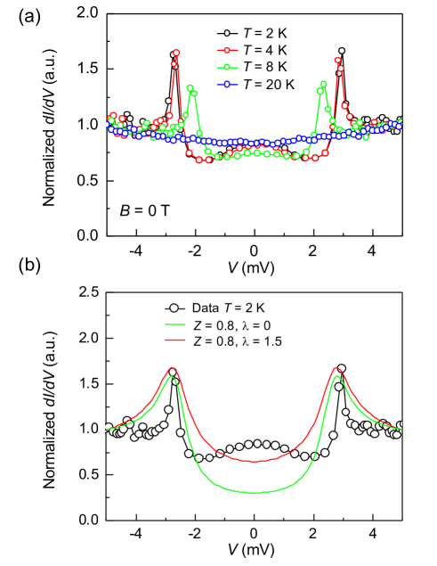
We now turn to the measured bias-dependence for differential conductance, , for a quasi-2D vdW F/S junction [recall its geometry in Fig. 2], shown in Fig. 6(a) for several . Some trends are expected, peaks reflect the peaks in the density of states, near Blonder et al. (1982), moving inward with as is also suppressed with . While the perfect transmission in 1D N/S geometry near implies the doubling of the normal-state conductance Blonder et al. (1982), since an incident electron through Andreev reflection contributes to the transfer of an electron pair across the N/S interface, the F/S transmission should be diminished, both by the interfacial barrier, parametrized by [recall Eq. (12)] as well by the spin polarization, , expected for Fe0.29TaS2 and measured in a similar Fe0.26TaS2 ferromagnet Yu et al. (2019). Only a fraction of the incident majority spin electrons can find the opposite spin partner for Andreev reflection Soulen Jr. et al. (1998); Žutić and Valls (2000).
With the NbN critical temperature, K, we focus on at the lowest K and theoretically explore the role of interfacial properties using dimensional parameters for barrier strength and Rashba SOC
| (31) | |||||
| (32) |
since we are interested in identifying trends with these interfacial parameters, rather than obtaining the best fit for , we further simplify this approach by considering the case for and .
Our calculated results are given in Fig. 6(b) and reflect these simplifications. For example, assuming that, and that is the free electron mass, the chosen dimensionless barrier strenght corresponds to m-1, consistent with NbN values Chockalingam et al. (2008), while eV, and nm is an average thickness among our studied F/S samples. The value of Rashba SOC, eVÅ2, which follows from the choice of , is also consistent with separate fits of the angular dependence of MR measured near zero bias in Ref. Cai et al. (2021).
By comparing and results at a fixed above the gap the changes are very small. However, the inclusion of Rashba SOC can strongly enhance the low-bias conductance. To understand the origin of this SOC effect, and similar trends from Sec. II, we note that in the normal state for the barrier region the dispersion is SOC split and shifted by the barrier potential (assuming ). As in Sec. II, a spinor of an incident electron with can be decomposed into barrier eigenspinors, , where from Eq. (27) has helicity . The two helicities have inequivalent effective barriers [recall Eqs. (13) and (14)]
| (33) |
Since , for positive helicity the barrier is enhanced, . However, for negative helicity, at , becomes effectively completely transparent, such can be viewed as “open channels” and are responsible for a strongly increased .
Some peculiar conductance trends can already be understood at and K, where the charge transport in F/S junctions is determined by conventional and spin-flip Andreev reflection with opposite and equal spin projection of the incident and reflected particle, respectively, corresponding to the spin-singlet and spin-triplet interfacial superconducting correlations. For plotted in the plane defined by and , a striking behavior was found for in the triangular region approximately delimited with lines T1 and T2 Vezin et al. (2020)
| (34) |
where is dominated by the spin-flip Andreev reflection and proximity-induced spin-triplet superconductivity.
Before showing next that a region in delimited by the lines T1 and T2 also pertains to the enhanced calculated MAAR, we comment on relaxing the assumption of equal masses and Fermi velocities in the F and S regions. In a simple 1D N/S case, without SOC, different Fermi velocities, , are known to increase the effective barrier strength, Blonder and Tinkham (1983). While this argument is often used to also ignore a Fermi velocity mismatch in the F/S case Soulen Jr. et al. (1998), as it is accounted for by simply enhancing , some subtleties exist Žutić and Valls (2000); Žutić and Das Sarma (1999). The mismatch of effective masses, , together with the mismatch of the Fermi wave vectors, , can then be viewed as determining and enhancing the effective . In our studies with SOC, implies that Eq. (33) should be generalized by replacing with , including in the expression for open channels and a vanishing . Even with such a wave vector mismatch, the spin-triplet contribution remains enhanced within a triangular region, as long as i.e., . The delimiting lines T1 and T2, for both and , have slopes modified by as compared to those given by Eq. (34).
V V. F/S Out-Of-Plane MAAR
Just as in the F/2DEG structures, the interplay between exchange field and Rashba SOC will lead to various nonmonotonic trends Högl et al. (2015); Vezin et al. (2020); Cai et al. (2021); Mizuno et al. (2009). Such trends can be inferred from Eqs. (33) and (34), as well as in the MR, which in F/S junctions corresponds to the superconducting counterpart of TAMR, and its term, MAAR (recall Sec. I), identified the key role of the Andreev reflection.
Similar to the significance of the condition for perfect transmission and contour matching in understanding the origin of an enhanced TAMR, for MAAR it is important to identify the influence of open channels Vezin et al. (2020). From Eq. (33), we see that yields vanishing with open channels located at the Fermi contour of radius
| (35) |
Open channels give the dominant contribution to and are also expected to determine the amplitude of MAAR.
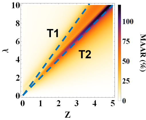
Since evanescent state for large do not contribute to they should be excluded in open channels. From the Snell’s law Žutić and Valls (2000), for the incident majority spin electron this implies that to have propagating scattering states, is required for conventional Andreev reflections and for dominant spin-flip Andreev reflections Žutić and Das Sarma (1999). The maximum of the total is achieved when the amount of the open channels , is maximized. For , in the two limiting case and we recover the conditions for lines T1 and T2 from Eq. (34), such that the maximum spin-flip Andreev reflection is located near i.e., .
From the calculated MAAR in Fig. 7 we see that the triangular region delimited by lines T1, T2 is also identifying the region of an enhanced MAAR and confirming the influence of open channels. Similar to our contour matching in TAMR, as noted in Sec. II., for a full picture the role of spin mismatch also needs to be included. Two characteristic features are easy to see from Fig. 7: (i) a large MAAR enhancement, which can reach 100 % and (ii) MAAR is nonomontonic with both and , when the other parameter is kept constant.
To understand (i), we recall that in the triangular region, the dominant contribution to the total is from the open channels that is associated with spin-flip Andreev reflection and spin-triplet pairing . Therefore, the total conductance can be approximately written as
where is the width of the open channels in -plane, is the angle between and , recall Eq. (27). For out-of-plane M, does not depend on due to the rotational symmetry and we can write
| (37) |
For in-plane M, considering the interplay between the incident electron spin and the barrier eigenspinor, the spin-flip Andreev reflection of an incident electron is given by Vezin et al. (2020). As a result, for in-plane M, we obtain
| (38) |
From Eq. (3), this means that MAAR in the triangular region is 100%, which explains that the previous prediction Högl et al. (2015) can be attributed to spin-triplet superconductivity and is also consistent with the largest values in the experimental results for Fe0.29TaS2/NbN junctions with a perpendicular magnetic anisotropy Cai et al. (2021).
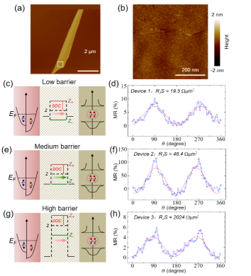
Despite our simple theoretical model to include the interplay of exchange field and SOC on the proximity-induced superconductivity in F/S junctions, such a description provides MAAR which is in a good agreement with the measured angular dependence of MR in Fig. 8. Remarkably, just as the variation of shows a nonmonotonic MAAR in Fig. 7 and a huge increase of MAAR at intermediate values, which with Rashba SOC can lead to a vanishing , we see that this trend in Figs. 8(d), (e), and (h) is also retained in the measured results obtained by varying the Al2O3 barrier thickness (nm).
While we cannot rule out a non-MAAR contribution in the measured low-bias MR for Fe0.29TaS2/NbN junctions, we can still examine its magnitude from several reported control measurements Cai et al. (2021). For example, by increasing above , MR is drastically reduced from its maximum at % in Fig. 8(f) and we can attribute the main MR part to a superconducting response. By considering MR in Al/Al2O3/NbN samples, we no longer have the interplay between the ferromagnetism and SOC, responsible for MAAR, but the resulting small MR of just few at K is encouraging that the presence of vortices at T has only a modest MR effect. Taken together, these findings confirm that MAAR is indeed the dominant source of the measured MR in Fig. 8, which further indicates that F0.29TaS2/NbN junctions, provide an important platform to realize elusive equal-spin-triplet superconductivity.
VI VI. Discussion and Conclusions
We have shown that Rashba SOC can lead to strongly enhanced magnetoresistance in junctions with one ferromagnet. Both in the normal-state and the superconducting response the calculated magnetoresistance is characterized by various nonmonotonic trends. While some of these trends and an enhanced magnetoresistance have been measured in superconducting junctions Martinez et al. (2020); Cai et al. (2021), experiments in the normal state are largely unexplored.
To realize magnetic proximity effects for the in-plane transport, magnetic insulators are desirable Žutić et al. (2019); Jiang et al. (2015); Wei et al. (2013); Lee et al. (2014). This precludes current flow in the more resistive F region [Fig. 1(a)] and minimizes hybridization with the 2DEG to enable a gate-tunable proximity-induced exchange splitting in their respective states. However, as shown in graphene Lazić et al. (2016); Zollner et al. (2016); Xu et al. (2018) for tunable magnetic proximity effects one could also employ ferromagnetic metals, separated by an insulating layer from the 2DEG .
For a suitable materials platform, which would support large magnetoresistive effects, we could extend our focus on simple Rashba SOC to a growing class of van der Waals (vdW) materials. Their heterostructure offer both transport in materials with strong SOC as well 2D ferromagnets Gong et al. (2017); Huang et al. (2017); Gong and Zhang (2019) with atomically-sharp interfaces and not limited to lattice-matching constraints. For example, transition-metal dichalcogenides in addition to their inherent SOC also provide spin-orbit proximity Avsar et al. (2014); Yan et al. (2016); Han et al. (2014); Dankert and Dash (2017); Wang et al. (2015); Antonio Benitez et al. (2019); Douli et al. (2020) and thereby alter spin textures and expected TAMR, while 2D ferromagnets support a versatile gate control Burch et al. (2018); Deng et al. (2018); Xing et al. (2017).
While we have focused on a longitudinal transport in a very simple system, the behavior emerging from a spin parity-time symmetry of the scattering states with perfect transmission is important not just in explaining a surprisingly large TAMR, but also as a sensitive probe to distinguish between trivial and topological states Shen et al. (2020). It would be interesting to know if our predicted nonmonotonic trends with interfacial parameters for TAMR could be also relevant for other transport phenomena in junctions with a single ferromagnet, such as spin-orbit torque and spin-Hall magnetoresistance Tsymbal and Žutić (2019); Belashchenko et al. (2020).
In the superconducting state, the observed large magnetoresistance has important implications as it provides an alternative probe for spin-triplet or mixed singlet-triplet superconductivity Gor’kov and Rashba (2001) and such a large signal is possible to realize even systems with only a modest SOC and negligible normal-state magnetoresistance Martinez et al. (2020). Since this work shows that spin-triplet superconductivity, desirable both for superconducting spintronics and Majorana bound states Amudsen et al. (2022), is feasible in simple structures with a single F and S region, it would also be important to extend its analysis to Josephson junctions, where enhanced magnetoresistance was predicted Costa et al. (2017), but not connected to the spin-triplet superconductivity, which was extensively studied in other Josephson junctions Khaire et al. (2010); Robinson et al. (2010); Banerjee et al. (2014); Valls (2022); Cai et al. (2023); Amudsen et al. (2022).
In our work, the nonmonotonic trends with the interfacial barrier strength were observed by comparing samples with different thickness of the (Al2O3). It would be desirable, to realize systems in which such changes, as well as the tunability of the Rashba SOC strength could be controlled in the same sample. A desirable progress is realized in Josephson junctions where currently there are no ferromagnetic regions, but the Zeeman splitting is due to an applied magnetic field Amudsen et al. (2022); Fornieri et al. (2019); Ren et al. (2019); Dartiailh et al. (2021); Zhou et al. (2022); Banerjee et al. (2022). Related experimental support in junctions with Al as a superconductor and InAs-based 2DEG already suggests an observation of topological spin-triplet superconductivity Dartiailh et al. (2021). In the same sample that both a reentrant superconductivity with an applied magnetic field and the jump in the superconducting phase are measured, but an enhanced magnetoresistance as another signature of spin-triplet superconductivity has not yet been studied.
VII Acknowledgments
We thank Thomas Vezin for useful discussions. We had a privilege of first meeting Professor Emmanuel Rashba at the Spintronics 2001: International Conference on Novel Aspects of Spin-Polarized Transport and Spin Dynamics in Washington, D.C. (chaired by one of us Žutić (2002)). He gave an insightful talk sharing his personal experience about relevant historic developments as well as a vision for the future opportunities in spintronics, conveyed further in his article Rashba (2002). Since then, through his valuable comments, we were able to better understand our own work and its broader context. His advice and guidance was not limited to semiconductor systems, and we again benefited from his comments which came soon after posting online our recent manuscript on spin-triplet superconductivity Cai et al. (2021). This work is supported by U.S. Department of Energy, Office of Science, Basic Energy Sciences under Award No. DE-SC0004890, the UB Center for Computational Research, National Basic Research Programs of China (No. 2019YFA0308401), and National Natural Science Foundation of China (No. 11974025).
References
- Maekawa and Gafvert (1982) S. Maekawa and U. Gafvert, “Electron tunneling between ferromagnetic films,” IEEE Trans. on Magn. 18, 707 (1982).
- Moodera et al. (1995) J. S. Moodera, Lisa R. Kinder, Terrilyn M. Wong, and R. Meservey, “Large Magnetoresistance at Room Temperature in Ferromagnetic Thin Film Tunnel Junctions,” Phys. Rev. Lett. 74, 3273 (1995).
- Žutić et al. (2004) I. Žutić, J. Fabian, and S. Das Sarma, “Spintronics: Fundamentals and applications,” Rev. Mod. Phys. 76, 323 (2004).
- Parkin et al. (2004) S. S. P. Parkin, C. Kaiser, A. Panchula, P. M. Rice, B. Hughes, M. Samant, and S.-H. Yang, “Giant tunneling magnetoresistance at room temperature with MgO (100) tunnel barriers,” Nat. Mater. 3, 862 (2004).
- Tsymbal and Žutić (2019) E. Y. Tsymbal and I. Žutić, eds., Spintronics Handbook Spin Transport and Magnetism, 2nd Edition (CRC Press, Taylor & Francis, Boca Raton, FL, 2019).
- Thomson (1857) W. Thomson, “On the electro-dynamic qualities of metals:–Effects of magnetization on the electric conductivity of nickel and of iron,” Proc. R. Soc. London 8, 546–550 (1857).
- Gould et al. (2004) C. Gould, C. Rüster, T. Jungwirth, E. Girgis, G. M. Schott, R. Giraud, K. Brunner, G. Schmidt, and L. W. Molenkamp, “Tunneling Anisotropic Magnetoresistance: A Spin-Valve-Like Tunnel Magnetoresistance Using a Single Magnetic Layer,” Phys. Rev. Lett. 93, 117203 (2004).
- Moser et al. (2007) J. Moser, A. Matos-Abiague, D. Schuh, W. Wegscheider, J. Fabian, and D. Weiss, “Tunneling Anisotropic Magnetoresistance and Spin-Orbit Coupling in Tunnel Junctions,” Phys. Rev. Lett. 99, 056601 (2007).
- Chantis et al. (2007) A. N. Chantis, K. D. Belashchenko, E. Y. Tsymbal, and M. van Schilfgaarde, “Tunneling Anisotropic Magnetoresistance Driven by Resonant Surface States: First-Principles Calculations on an Fe(001) Surface,” Phys. Rev. Lett. 98, 046601 (2007).
- Fabian et al. (2007) J. Fabian, A. Matos-Abiague, C. Ertler, P. Stano, and I. Žutić, “Semiconductor spintronics,” Acta Phys. Slov. 57, 565 (2007).
- Shen et al. (2020) C. Shen, T. Leeney, A. Matos-Abiague, B. Scharf, J. E. Han, and I. Žutić, “Resonant tunneling anisotropic magnetoresistance induced by magnetic proximity,” Phys. Rev. B 102, 045312 (2020).
- Bychkov and Rashba (1984) Yu. A. Bychkov and E. I. Rashba, “Properties of a 2D with lifted spectral degeneracy,” Zh. Eksp. Teor. Fiz. Pisma Red. 39, 66 (1984), [JETP Lett. 39, 78 (1984)].
- Cai et al. (2023) R. Cai, I. Žutić, and W. Han, “Superconductor/ferromagnet heterostructures for superconducting spintronics and quantum computation,” Adv. Quant. Tech. 6, 2200080 (2023).
- Amudsen et al. (2022) M. Amudsen, J. Linder, J. W. A. Robinson, I. Žutić, and N. Banerjee, “Colloquium: Spin-orbit effects in superconducting hybrid structures,” arXiv:2210.03549 (2022).
- Eschrig (2015) M. Eschrig, “Spin-polarized supercurrents for spintronics: A review of current progress,” Rep. Prog. Phys. 78, 104501 (2015).
- Linder and Robinson (2015) J. Linder and J. W. A. Robinson, “Superconducting spintronics,” Nat. Phys. 11, 307 (2015).
- Buzdin (2005) A. I. Buzdin, “Proximity effects in superconductor-ferromagnet heterostructures,” Rev. Mod. Phys. 77, 935 (2005).
- Bergeret et al. (2005) F. S. Bergeret, A. F. Volkov, and K. B. Efetov, “Odd triplet superconductivity and related phenomena in superconductor-ferromagnet structures,” Rev. Mod. Phys. 77, 1321 (2005).
- Kitaev (2001) A. Yu Kitaev, “Unpaired Majorana fermions in quantum wires,” Phys.-Usp. 44, 131 (2001).
- Aasen et al. (2016) D. Aasen, M. Hell, R. V. Mishmash, A. Higginbotham, J. Danon, M. Leijnse, T. S. Jespersen, J. A. Folk, C. M. Marcus, K. Flensberg, and J. Alicea, “Milestones toward Majorana-based quantum computing,” Phys. Rev. X 6, 031016 (2016).
- Güngördü and Kovalev (2022) U. Güngördü and Alexey A. Kovalev, “Majorana bound states with chiral magnetic textures,” J. Appl. Phys. 132, 041101 (2022).
- Laubscher and Klinovaja (2021) K. Laubscher and J. Klinovaja, “Majorana bound states in semiconducting nanostructures,” J. Appl. Phys. 130, 081101 (2021).
- Žutić et al. (2019) I. Žutić, A. Matos-Abiague, B. Scharf, H. Dery, and K. Belashchenko, “Proximitized materials,” Mater. Today 22, 85 (2019).
- Akimov et al. (2017) I. A. Akimov, M. Salewski, I. V. Kalitukha, S. V. Poltavtsev, J. Debus, D. Kudlacik, V. F. Sapega, N. E. Kopteva, E. Kirstein, E. A. Zhukov, D. R. Yakovlev, G. Karczewski, M. Wiater, T. Wojtowicz, V. L. Korenev, Yu. G. Kusrayev, and M. Bayer, “Direct measurement of the long-range p-d exchange coupling in a ferromagnet-semiconductor Co/CdMgTe/CdTe quantum well hybrid structure,” Phys. Rev. B 96, 184412 (2017).
- Korenev et al. (2019) V. L. Korenev, I. V. Kalitukha, I. A. Akimov, V. F. Sapega, E. A. Zhukov, E. Kirstein, O.S. Ken, D. Kudlacik G. Karczewski, M. Wiater, T. Wojtowicz, N. D. Ilyinskaya, N.M. Lebedeva, T.A. Komissarova, Yu. G. Kusrayev, D.R. Yakovlev, and M. Bayer, “Low voltage control of exchange coupling in a ferromagnet-semiconductor quantum well hybrid structure,” Nat. Commun. 10, 2899 (2019).
- Takiguchi et al. (2019) K. Takiguchi, L. D. Anh, T. Chiba, T. Koyama, D. Chiba, and M. Tanaka, “Giant gate-controlled proximity magnetoresistance in semiconductor-based ferromagnetic/non-magnetic bilayers,” Nat. Phys. 15, 1134 (2019).
- Betthausen et al. (2012) C. Betthausen, T. Dollinger, H. Saarikoski, V. Kolkovsky, G. Karczewski, T. Wojtowicz, K. Richter, and D. Weiss, “Spin-transistor action via tunable Landau-Zener transitions,” Science 337, 324 (2012).
- Griffiths (2005) D. J. Griffiths, Introduction to Quantum Mechanics, Second Edition (Pearson Prentice Hall, Upper Saddle River, NJ, 2005).
- Sakurai and Napolitano (2011) J. J. Sakurai and J. Napolitano, Modern Quantum Mechanics, Second Edition (Addison-Wesley, San Francisco, CA, 2011).
- Cai et al. (2021) R. Cai, Y. Yao, P. Lv, Y. Ma, W. Xing, B. Li, Y. Ji, H. Zhou, C. Shen, S. Jia, X. C. Xie, I. Žutić, Q.-F. Sun, and W. Han, “Evidence for anisotropic spin-triplet Andreev reflection at the 2D van der Waals ferromagnet/superconductor interface,” Nat. Commun. 12, 6725 (2021).
- Žutić and Das Sarma (1999) I. Žutić and S. Das Sarma, “Spin-polarized transport and Andreev reflection in semiconductor/superconductor hybrid structures,” Phys. Rev. B 60, R16322 (1999).
- Högl et al. (2015) P. Högl, A. Matos-Abiague, I. Žutić, and J. Fabian, “Magnetoanisotropic Andreev Reflection in Ferromagnet-Superconductor Junctions,” Phys. Rev. Lett. 115, 116601 (2015).
- Vezin et al. (2020) T. Vezin, C. Shen, J. E. Han, and I. Žutić, “Enhanced spin-triplet pairing in magnetic junctions with -wave superconductors,” Phys. Rev. B 101, 014515 (2020).
- Lv et al. (2018) P. Lv, Y.-F. Zhou, N.-X. Yang, and Q.-F. Sun, “Magnetoanisotropic spin-triplet Andreev reflection in ferromagnet-Ising superconductor junctions,” Phys. Rev. B 97, 144501 (2018).
- Winkler (2003) R. Winkler, Spin-Orbit Coupling Effects in Two-Dimensional Electron and Hole Systems (Springer, New York, 2003).
- Rozhansky et al. (2016) I. V. Rozhansky, N. S. Averkiev, and E. Lähderanta, “Resonant tunneling between two-dimensional layers accounting for spin-orbit interaction,” Phys. Rev. B 93, 195405 (2016).
- Liu et al. (2018) H. Liu, E. Marcellina, A. R. Hamilton, and D. Culcer, “Strong Spin-Orbit Contribution to the Hall Coefficient of Two-Dimensional Hole Systems,” Phys. Rev. Lett. 121, 087701 (2018).
- Arovas and Lyanda-Geller (1998) D. P. Arovas and Y. Lyanda-Geller, “Non-Abelian geometric phases and conductance of spin-3/2 holes,” Phys. Rev. B 57, 12302 (1998).
- Girvin and Yang (2019) S. M. Girvin and K. Yang, Modern Condensed Matter Physics (Cambridge University Press, Cornwall, UK, 2019).
- Blonder et al. (1982) G. E. Blonder, M. Tinkham, and T. M. Klapwijk, “Transition from metallic to tunneling regimes in superconducting microconstrictions: Excess current, charge imbalance, and supercurrent conversion,” Phys. Rev. B 25, 4515 (1982).
- Blonder and Tinkham (1983) G. E. Blonder and M. Tinkham, “Metallic to tunneling transition in Cu-Nb point contacts,” Phys. Rev. B 27, 112 (1983).
- Žutić and Valls (2000) I. Žutić and O. T. Valls, “Tunneling spectroscopy for ferromagnet/superconductor junctions,” Phys. Rev. B 61, 1555 (2000).
- Nikolić et al. (2005) B. K. Nikolić, L. P. Zârbo, and S. Souma, “Mesoscopic spin Hall effect in multiprobe ballistic spin-orbit-coupled semiconductor bridges,” Phys. Rev. B 72, 075361 (2005).
- Scharf et al. (2016) B. Scharf, A. Matos-Abiague, J. E. Han, E. M. Hankiewicz, and I. Žutić, “Tunneling Planar Hall Effect in Topological Insulators: Spin Valves and Amplifiers,” Phys. Rev. Lett. 117, 166806 (2016).
- Park et al. (2008) B. G. Park, J. Wunderlich, D. A. Williams, S. J. Joo, K. Y. Jung, K. H. Shin, K. Olejnik, A. B. Shick, and T. Jungwirth, “Tunneling Anisotropic Magnetoresistance in Multilayer- Structures,” Phys. Rev. Lett. 100, 087204 (2008).
- Uemura et al. (2009) T. Uemura, Y. Imai, M. Harada, K. Matsuda, and M. Yamamoto, “Tunneling anisotropic magnetoresistance in epitaxial CoFe/n-GaAs junctions,” Appl. Phys. Lett. 94, 182502 (2009).
- Griffin and Demers (1971) A. Griffin and J. Demers, “Tunneling in the normal-metal-insulator-superconductor geometry using the Bogoliubov equations of motion,” Phys. Rev. B 4, 2202 (1971).
- Kashiwaya and Tanaka (2000) S. Kashiwaya and Y. Tanaka, “Tunneling effects on surface bound states in unconventional superconductors,” Rep. Prog. Phys. 63, 1641 (2000).
- Wu and Samokhin (2009) S. Wu and K. V. Samokhin, “Tunneling conductance of ferromagnet/noncentrosymmetric superconductor junctions,” Phys. Rev. B 80, 014516 (2009).
- Matos-Abiague and Fabian (2009) A. Matos-Abiague and J. Fabian, “Anisotropic tunneling magnetoresistance and tunneling anisotropic magnetoresistance: Spin-orbit coupling in magnetic tunnel junctions,” Phys. Rev. B 79, 155303 (2009).
- Yu et al. (2019) X.-Y. Yu, H.-L. Feng, G.-X. Gu, Y.-H. Liu, Z.-L. Li, T.-S. Xu, and Y.-Q. Li, “Andreev reflection spectroscopy of ferromagnetic fe0.26tas2 with layered structure,” Acta Phys. Sin. 68, 247201 (2019).
- Soulen Jr. et al. (1998) R. J. Soulen Jr., J. M. Byers, M. S. Osofsky, B. Nadgorny, T. Ambrose, S. F. Cheng, P. R. Broussard, C. T. Tanaka, J. Nowak, J. S. Moodera, A. Barry, and J. M. D. Coey, “Measuring the spin polarization of a metal with a superconducting point contact,” Science 282, 85 (1998).
- Chockalingam et al. (2008) S. P. Chockalingam, M. Chand, J. Jesudasan, V. Tripathi, and P. Raychaudhuri, “Superconducting properties and Hall effect of epitaxial NbN thin films,” Phys. Rev. B 77, 214503 (2008).
- Mizuno et al. (2009) Y. Mizuno, T. Yokoyama, and Y. Tanaka, “Theory of charge transport in ferromagnetic semiconductor/s-wave superconductor junction,” Phys. Rev. B 80, 195307 (2009).
- Martinez et al. (2020) I. Martinez, P. Högl, C. González-Ruano, J. P. Cascales, C. Tiusan, Y. Lu, M. Hehn, A. Matos-Abiague, J. Fabian, I. Žutić, and F. G. Aliev, “Interfacial Spin-Orbit Coupling: A Platform for Superconducting Spintronics,” Phys. Rev. Applied 13, 014030 (2020).
- Jiang et al. (2015) Z. Jiang, C. Z. Chang, C. Tang, P. Wei, J. S. Moodera, and J. Shi, “Independent tuning of electronic properties and induced ferromagnetism in topological insulators with heterostructure approach,” Nano Lett. 15, 5835 (2015).
- Wei et al. (2013) P. Wei, F. Katmis, B. A. Assaf, H. Steinberg, P. Jarillo-Herrero, D. Heiman, and J. S. Moodera, “Exchange-Coupling-Induced Symmetry Breaking in Topological Insulators,” Phys. Rev. Lett. 110, 186807 (2013).
- Lee et al. (2014) A. T. Lee, M. J. Han, and K. Park, “Magnetic proximity effect and spin-orbital texture at the Bi2Se3/EuS interface,” Phys. Rev. B 90, 155103 (2014).
- Lazić et al. (2016) P. Lazić, K. D. Belashchenko, and I. Žutić, “Effective gating and tunable magnetic proximity effects in two-dimensional heterostructures,” Phys. Rev. B 93, 241401(R) (2016).
- Zollner et al. (2016) K. Zollner, M. Gmitra, T. Frank, and J. Fabian, “Theory of Proximity-Induced Exchange Coupling in Graphene on hBN/(Co,Ni),” Phys. Rev. B 94, 155441 (2016).
- Xu et al. (2018) J. Xu, S. Singh, J. Katoch, G. Wu, T. Zhu, I. Žutić, and R. K. Kawakami, “Spin inversion in graphene spin valves by gate-tunable magnetic proximity effect at one-dimensional contacts,” Nat. Commun 9, 2869 (2018).
- Gong et al. (2017) C. Gong, L. Li, Z. Li, H. Ji, A. Stern, Y. Xia, T. Cao, W. Bao, C. Wang, Y. Wang, Z. Q. Qiu, R. J. Cava, S. G. Louie, J. Xia, and X. Zhang, “Discovery of intrinsic ferromagnetism in two-dimensional van der Waals crystals,,” Nature 546, 265 (2017).
- Huang et al. (2017) B. Huang, G. Clark, E. Navarro-Moratalla, D. R. Klein, R. Cheng, K. L. Seyler, D. Zhong, E. Schmidgall, M. A. McGuire, D.H. Cobden, W. Yao, D. Xiao, P. Jarillo-Herrero, and X. Xu, “Layer-dependent ferromagnetism in a van der Waals crystal down to the monolayer limit,” Nature 546, 270 (2017).
- Gong and Zhang (2019) C. Gong and X. Zhang, “Two-Dimensional Magnetic Crystals and Emergent Heterostructure Devices,” Science 363, eaav4450 (2019).
- Avsar et al. (2014) A. Avsar, J. Y. Tan, T. Taychatanapat, J. Balakrishnan, G. K. W. Koon, Y. Yeo, J. Lahiri, A. Carvalho, A. S. Rodin, E. C. T. O’Farrell, G. Eda, A. H. Castro Neto, and B. Özyilmaz, “Spin-orbit proximity effect in graphene,” Nat. Commun. 5, 4875 (2014).
- Yan et al. (2016) W. Yan, O. Txoperena, R. Llopis, H. Dery, L. E. Hueso, and F. Casanova, “A two-dimensional spin field-effect switch,” Nat. Commun. 7, 13372 (2016).
- Han et al. (2014) W. Han, R. K. Kawakami, M. Gmitra, and J. Fabian, “Graphene spintronics,” Nat. Nanotechnol. 9, 794 (2014).
- Dankert and Dash (2017) A. Dankert and S. P. Dash, “Electrical gate control of spin current in van der Waals heterostructures at room temperature,” Nat. Commun. 8, 16093 (2017).
- Wang et al. (2015) Z. Wang, D.-K. Ki, H. Chen, H. Berger, A. H. MacDonald, and A. F. Morpurgo, “Strong interface-induced spin-orbit interaction in graphene on WS2,” Nat. Commun. 6, 8839 (2015).
- Antonio Benitez et al. (2019) L. Antonio Benitez, J. F. Sierra, W. Savero Torres, M. Timmermans, M. V. Costache, and S. O. Valenzuela, “Investigating the spin-orbit interaction in van der Waals heterostructures by means of the spin relaxation anisotropy,” APL Mater. 7, 120701 (2019).
- Douli et al. (2020) K. Douli, M. D. Petrović, K. Zollner, P. Plechac, J. Fabian, and B. K. Nikolić, “Proximity spin-orbit torque on a two-dimensional magnet within van der Waals heterostructure: Current-driven antiferromagnet-to-ferromagnet reversible nonequilibrium phase transition in bilayer CrI3,” Nano Lett. 20, 2288 (2020).
- Burch et al. (2018) K. S. Burch, D. Mandrus, and J.-G. Park, “Magnetism in two-dimensional van der Waals materials,” Nature 563, 47 (2018).
- Deng et al. (2018) Y. Deng, Y.Yu, Y. Song, J. Zhang, N. Z. Wang, Z. Sun, Y. Yi, Y. Z. Wu, S. Wu, J. Zhu, J. Wang, X. H. Chen, and Y. Zhang, “Gate-tunable room-temperature ferromagnetism in two-dimensional Fe3GeTe2,” Nature 563, 94 (2018).
- Xing et al. (2017) W. Xing, Y. Chen, P. M. Odenthal, X. Zhang, W. Yuan, T. Su, Q. Song, T. Wang, J. Zhong, S. Jia, X. C. Xie, Y. Li, and W. Han, “Electric field effect in multilayer Cr2Ge2Te6: A ferromagnetic 2D material,” 2D Mater. 4, 024009 (2017).
- Belashchenko et al. (2020) K.D. Belashchenko, A.A. Kovalev, and M. van Schilfgaarde, “Interfacial contributions to spin-orbit torque and magnetoresistance in ferromagnet/heavy-metal bilayers,” Phys. Rev. B 101, 020407(R) (2020).
- Gor’kov and Rashba (2001) L. P. Gor’kov and E. I. Rashba, “Superconducting 2D system with lifted spin degeneracy: Mixed single-triplet state,” Phys. Rev. Lett 87, 037004 (2001).
- Costa et al. (2017) A. Costa, P. Högl, and J. Fabian, “Magnetoanisotropic Josephson effect due to interfacial spin-orbit fields in superconductor/ferromagnet/superconductor junctions,” Phys. Rev. B 95, 024514 (2017).
- Khaire et al. (2010) T. S. Khaire, M. A. Khasawneh, W. P. Pratt, Jr., and N. O. Birge, “Observation of spin-triplet superconductivity in Co-based Josephson junctions,” Phys. Rev. Lett. 104, 137002 (2010).
- Robinson et al. (2010) J. W. A. Robinson, J. D. S. Witt, and M. G. Blamire, “Controlled injection of spin-triplet supercurrents into a strong ferromagnet,” Science 329, 59 (2010).
- Banerjee et al. (2014) N. Banerjee, J. W. A. Robinson, and M. G. Blamire, “Reversible control of spin-polarised supercurrents in ferromagnetic Josephson junctions,” Nat. Commun. 5, 4771 (2014).
- Valls (2022) O. T. Valls, Superconductor/Ferromagnet Nanostructures (World Scientific, Hackensack, NJ, 2022).
- Fornieri et al. (2019) A. Fornieri, A. M. Whiticar, F. Setiawan, E. Portolés, A. C. C. Drachmann, A. Keselman, S. Gronin, C. Thomas, T. Wang, R. Kallaher, G. C. Gardner, E. Berg, M. J. Manfra, A. Stern, C. M. Marcus, and F. Nichele, “Evidence of topological superconductivity in planar Josephson junctions,” Nature 569, 89 (2019).
- Ren et al. (2019) H. Ren, F. Pientka, S. Hart, A. T. Pierce, M. Kosowsky, L. Lunczer, R. Schlereth, B. Scharf, E. M. Hankiewicz, L. W. Molenkamp, B. I. Halperin, and A. Yacoby, “Topological superconductivity in a phase-controlled Josephson junction,” Nature 569, 93 (2019).
- Dartiailh et al. (2021) M. C. Dartiailh, W. Mayer, J. Yuan, K. S. Wickramasinghe, A. Matos-Abiague, I. Žutić, and J. Shabani, “Phase signature of topological transition in Josephson junctions,” Phys. Rev. Lett. 126, 036802 (2021).
- Zhou et al. (2022) T. Zhou, M. C. Dartiailh, K. Sardashti, J. E. Han, A. Matos-Abiague, J. Shabani, and I. Žutić, “Fusion of Majorana bound states with mini-gate control in two-dimensional systems,” Nat. Commun. 13, 1738 (2022).
- Banerjee et al. (2022) A. Banerjee, O. Lesser, M. A. Rahman, H.-R. Wang, M.-R. Li, A. Kringhøj, A. M. Whiticar, A. C. C. Drachmann, C. Thomas, T. Wang, M. J. Manfra, E. Berg, Y. Oreg, A. Stern, and C. M. Marcus, “Signatures of a topological phase transition in a planar Josephson junction,” arXiv:2201.03453 (2022).
- Žutić (2002) I. Žutić, “Novel aspects of spin-polarized transport and spin dynamics,” J. Supercond. 15, 5 (2002).
- Rashba (2002) E. I Rashba, “Spintronics: Sources and challenge. Personal perspective,” J. Supercond. 15, 13 (2002).