Supplementary Material for:
Generation of Large Vortex-Free Superfluid Helium Nanodroplets
I Experimental Setup
Single-shot x-ray coherent diffractive imaging of xenon nanostructures assembled inside helium droplets was performed at the Small Quantum Systems (SQS) instrument of the European X-ray Free Electron Laser (XFEL). The SQS instrument is comprised of multiple experimental end stations [1]. For our measurements, we used the Nano-sized Quantum System (NQS) station, which was designed to study nonlinear and time-resolved responses of nanometer-scale atomic and molecular clusters after irradiation with ultrashort and ultrabright x-rays pulses with photon energies ranging from to [1]. Our experimental setup consisted of three parts: the sample source system, the main chamber where the x-ray beam intersected the sample beam and where several detectors were installed, and the quadrupole mass spectrometer (QMS), which was used for the characterization of the sample beam. Large helium nanodroplets in this study were generated using a non-standard approach, deviating from the typical method of utilizing a pinhole nozzle at temperatures below . Instead, a significantly larger conical nozzle with a temperature of up to was employed. Such a nozzle allows large clusters/droplets to be grown from the gas phase in a much slower process. It is well-established that they grow by collision and coagulation, and they are expected to have smaller angular momentum, see section ”Droplet Growth by Collision and Coagulation” for a more comprehensive discussion of our growth model.
The helium droplets were generated by expanding a pre-cooled pressurized gas into the source chamber through a conical nozzle constructed out of stainless steel with a throat diameter of , a half-opening angle of , a channel length of , and an equivalent diameter of , calculated using , where and correspond to the nozzle’s throat diameter and opening half-angle, respectively [2, 3, 4]. This nozzle was perched atop a pulsed valve (Series 99 , Parker Hannifin Corporation), see Fig. S1. An oxygen-free copper casing enclosed the nozzle and valve assembly and was connected to the second stage of a closed-cycle cryocooler (RDK415E, Sumitomo Heavy Industries). In this experiment, the stagnation pressure was varied from to , and the nozzle temperature from to . An IOTA One pulse driver (Parker Hannifin Corporation) controlled the opening time and cycle of the valve. The driver operation settings were tuned to minimize heat produced by the valve operation. Specifically, about was initially applied to initiate the opening of the valve for , followed by a holding voltage of for another . As determined in exploratory measurements, the total opening time of should guarantee continuous flow conditions. With these settings and at an opening cycle of , the valve could be cooled to at a stagnation pressure of . The nozzle can be cooled further to by reducing the valve’s opening cycle to . For operating the valve at temperatures greater than , the valve was heated using resistance heating cartridges attached to the nozzle assembly. A comparison of the droplets generated using different nozzle shapes is given at the end of this supplement.
Once formed, the droplets passed through a diameter skimmer, located about from the nozzle, into the doping chamber. Here, a long, cylindrical gas cell with an entrance and exits holes of and , respectively, was installed. The gas cell was positioned about from the nozzle, and its holes are large enough to allow the droplet stream to pass unobstructed. The helium droplets could pick up xenon atoms through inelastic collisions as they pass through the gas cell. Additionally, the doping level was controlled by regulating the xenon pressure in the cell. A differential pumping stage was installed after the doping chamber with a skimmer separating them. The differential stage was about long, half of which protrudes into the main chamber.
In the main chamber, the helium droplet beam crossed the x-ray pulses. The x-ray photons were generated by the SASE3 undulator of the European XFEL, which for this experiment was operated with a photon energy of , a nominal pulse duration of (estimated based on the electron bunch charge), and an initial pulse energy of to as measured after the undulators. A pair of Kirkpatrick-Baez mirrors focuses the x-ray beam to a diameter of with a Rayleigh length of about . During a diffraction event, a single droplet was hit by a single XFEL pulse, and the scattered photons were collected by a pnCCD (pn-junction Charge Couple Device) detector located after the interaction point [5]. The number of x-ray pulses per train was increased to five when the nozzle is operated at to increase the probability of a hit. Note that the time delay between the arrival of the x-ray pulse and the different portions of the droplet beam due to the opening of the valve can be varied. Finally, the droplet beam terminated in a diagnostic chamber that housed an Extrel Max 500 QMS, which was used for determining the average droplet size following the droplet titration technique [6].
II Image Data Processing
II.1 Raw Data Preprocessing and Hit Finding
The complete data collected and stored from the pnCCD is a set of hits and non-hits. Diffraction images of pure and doped helium droplets belong to the hit subset, whereas the non-hit subset contains empty frames. Before hits were searched, the readout artifacts from the raw pnCCD image data were first removed by applying pedestal, common mode, and gain corrections. Additionally, the intensities were converted to photon counts. More details on the preprocessing of the pnCCD images are described in Ref. [5].
After image preprocessing, hits were identified by the number of lit pixels, i.e., number of pixels with values larger than photons. A threshold of lit pixels usually yields sufficient signal to determine, at least, the droplet size from a diffraction image. The background stray light for each diffraction event was calculated from the average of the 50 nearest non-hit events and removed using a discrete photon countdown method. In this method, the background and the diffraction image were first divided into chunks of pixels, respectively. The average number of background photons was calculated. In each chunk, a pixel is randomly selected and a photon is subtracted one by one until the number of background photons is eliminated or until no photon is left in the same area.
The hit rate depends on the droplet number density inside the focal volume of the FEL [7, 8] and is on the order of in our measurements. Such a low hit rate suggests a low droplet number density, making it highly unlikely to observe multiple droplets arriving concurrently in the interaction region.
II.2 Image Centering
The pnCCD detector in our imaging setup consisted of two autonomous panels, each with pixels [5]. The relative arrangement between these panels was obtained by considering a subset of diffraction images from a pure droplet and independently fitting ellipses into the diffraction contours lying on each half. The centers of the ellipses were then overlapped, where the relative separation was determined. Finally, this separation was used to recalibrate the absolute encoder positions of the motors controlling the detector and was then applied to all other images within the same data set.
Due to the pointing instability of the x-ray beam, the exact center of a diffraction pattern could vary by pixels from shot to shot. Since inaccurate centering of the diffraction leads to spurious image reconstruction, the exact center of each image was determined iteratively. First, a pixels region of interest (ROI) was selected around the initial center position. This ROI included the gap between the two halves of the detector. Then, the upper ROI half pixels and the rotated lower half were cross correlated to determine a better diffraction center point. This procedure normally converged quickly to the best center point after a few iterations. For large droplets or those with strong absorption effects inside the droplet, the diffraction patterns can break Friedel’s symmetry and can lead to incorrect center determination. In this case, the center position was adjusted manually until the phase ramps, introduced by displacements in the Fourier domain, were eliminated in the spatial domain.
II.3 Droplet Size and Shape Determination
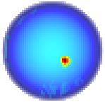
Because pure helium droplets are mostly spheroidal with a homogeneous density and negligible absorption, their radial scattering profile can be approximated as that of a non-absorbing sphere, described as [9]
| (S1) |
where is the droplet’s radius and is the scattering vector for wavelength into angle . Here, is the droplet volume and is an amplitude parameter. The droplet radius was extracted from the diffraction images of pure helium droplet by fitting Eq. (S1) into their radial profiles. Figure S2 shows the size distributions of the helium droplets generated using a conical nozzle at six different droplet source conditions used in this experiment; a total of 1640 images was processed for droplet size determination. Again, the droplet size is given as the number of helium atoms in a droplet and is related to the droplet’s radius through [10, 7]. The arithmetic average droplet size are reported and gives an upper limit to the statistics.
The shape of a droplet was obtained from the autocorrelation (inverse Fourier transform) of its diffraction pattern, whose extent is twice the size of a droplet’s projection onto the detector plane. Because of the central detector hole, the diffraction is high-pass filtered, and its inverse Fourier transform shows an outline. This outline was isolated by applying edge detection techniques and used as input for an elliptical fit that yields the semi-major axis and semi-minor axis . Data points within of the detector gap axis were excluded in the fitting. A total number of images of undoped droplets yielded satisfactory results and were used for determining the droplet’s size and shape distributions. A droplet’s mean radius was calculated as and the aspect ratio of the projection onto the detector plane as . The resulting size distributions are compared to the distributions from radial diffraction profiles in Fig. S2. Since shape determination from autocorrelation is more susceptible to noise, the sample size is smaller, especially for smaller droplets with . Nevertheless, both distributions show the same overall behavior. The aspect ratio distributions of the undoped droplets in this experiment are shown in Fig. S3.
II.4 Image Reconstruction for Doped Droplets
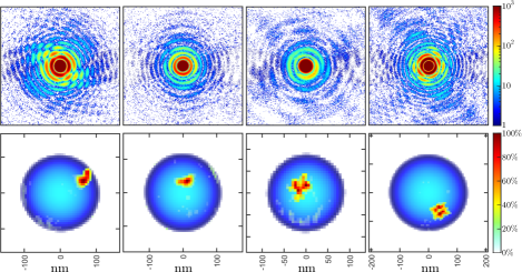
Prior to numerical image reconstruction, the sizes and shapes of 746 xenon-doped droplets were determined using the autocorrelation method described above. Each diffraction image was assembled, centered, and cropped to an area of pixels before rebinning to pixels to improve the signal-to-noise ratio. Then, a bow tie-shaped mask was applied to mask out areas corresponding to the detector hole, the gap between the pnCCD panels, and the regions with strong background stray light, see example in Fig. S4. Additionally, a Gaussian low-pass filter with pixels was applied to the outer region of the diffraction pattern, retaining only diffraction angles .
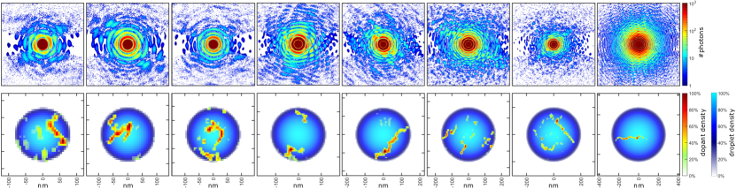
The two main categories of dopant structures, as displayed in Fig. 2 of the main text, are: compact xenon clusters, which are associated with vortex-free aggregation; and xenon-traced vortex filaments, which are associated with vortex-induced aggregation. To ensure that vortices are not incorrectly categorized as compact clusters due to poor resolution, diffraction images with low signal-to-noise ratios were filtered out. The achievable intensity limited resolution depends on the largest momentum transfer (i.e., diffraction angle) with sufficient intensity. Assuming that statistical noise has the biggest contribution, signal-to-noise ratio can be estimated from the radial diffraction profile . Since the relevant quantity for iterative phase reconstructions is the modulus of the diffraction amplitude instead of the intensity, the Poisson signal-to-noise ratio is given by , with being the number of photons per pixel [11]. Thus, the lower resolution limit can be estimated by choosing an intensity-dependent threshold, e.g., the Rose criterion [12], and deriving from it. Diffraction images with insufficient resolution for unambiguous categorization as well as cases where the droplet size was in the order of the resolution limit were excluded in this step, leaving scattering patterns whose reconstructed doping structures are well above noise. Resolutions with much smaller signal-to-noise ratios have been reported previously (e.g., photon/pixel in [13]) and further down-binning to the Shannon pixel would also increase the signal-to-noise ratio, leading to considerably higher resolutions than that estimated with this approach; see discussion in Refs. [14] and [11]. From the 392 reconstructions, 330 could be classified in either one of the dopant categories; their corresponding counts are shown in Fig. 3 in the main text. Structures that cannot be conclusively classified as either compact or filament are shown in Fig. S5 and serve as a classification error.
The numerical image reconstructions were calculated using a modified version of the droplet coherent diffractive imaging algorithm (DCDI) [18]. The calculated projection of the droplet density from the shape fit described above was used as a starting condition in the spatial domain. In the frequency domain, the Fourier transform of the droplet density was used to obtain the initial phases and for the amplitudes in the masked regions. The density was normalized to the intensity of the diffraction pattern in the unmasked region. Since scattering from dopants contributes to the total intensity, the diffraction from the droplets is overestimated and is corrected by a scaling parameter to account for the contribution of the dopants to the scattering. For most reconstructions, the value of was set to ; in some cases, the value was varied between and . To be consistent with the Rose criterion, the noise threshold parameter was set to , where
| (S2) |
is the standard deviation of the image noise [19], and the standard deviation of the diffraction amplitude of pixel ; for details, see Ref. [19]. Additionally, the positivity constraint was applied in the spatial domain for the real and imaginary, respectively. Finally, the DCDI algorithm was iterated for 100 cycles, which are sufficient for convergence [18].
III Angular Momentum Estimations
III.1 From Droplet Shape
The droplets generated using a conical nozzle have evidently smaller aspect ratios as compared to those generated in previous experiments using a pinhole nozzle [20, 21, 22, 23] at the same stagnation conditions. This already suggests that the means of droplet generation is crucial to controlling the droplet’s rotational state. A more deformed droplet generally indicates larger angular momentum due to the presence of multiple vortices, whereas, a close-to-spherical droplet has small angular momentum and may have few or no vortices in addition to the presence of capillary waves on the droplet’s surface [24, 16, 17]. To benchmark the rotational state of the droplets produced here, their angular momentum is estimated from their mean droplet size and aspect ratio , similar to the approach performed in Refs. [25, 23]. Starting from the average aspect ratio obtained from the two-dimensional projection of the droplet’s shape on the detector plane, the three-dimensional average aspect ratio can be estimated using [23], from which the reduced angular momentum are determined from tabulated values. Then, the average angular momentum is calculated using [15]
| (S3) |
where is the bulk liquid helium density at low temperatures, is the droplet radius with and being the mass, and is the surface tension of helium at low temperatures [26]. Two sets of tabulated values are used: the first considers a droplet following a rigid-body rotation and thus conforms to the stability curve of a rotating viscous droplet [15] (see Figs. S3(A) and (B) in Ref. [20] and Fig. 4 in Ref. [23]), while the second assumes that all angular momenta is carried by capillary waves on the droplet’s surface [24, 16, 17]. The results of these estimates are tabulated in Table S1. The calculated angular momenta using the rigid-body approach suggest that multiple vortices should have been observed in the experiment, where [25]. On the other hand, the estimates from the capillary waves approach indicate that no straight vortex would be expected since it requires an angular momentum per atom of [24, 27, 28]. Calculations are available on how the angular momentum is partitioned between the co-existence of vortices and capillary waves in prolate-shaped droplets, and how the presence of multiple vortices accommodates most of the angular momentum of the droplet [25, 17]. However, these calculation were only performed in rather smaller droplets containing a few tens of thousand atoms given the exorbitant computational cost associated in performing DFT calculations and may not be easily extendable for droplet sizes relevant to this experiment ( atoms). Therefore, the angular momentum calculation of these large superfluid droplets, which may contain a combination of few vortices and surface capillary waves requires further study, considering especially that the computational rubric must consider the interplay between the position of an off-centered curved vortex in the droplet and the droplet shape itself.
III.2 From Droplet Growth Through Collision and Coagulation
One possible explanation why vortex-induced aggregation is still observed for droplets produced by gas condensation is that these droplets acquire angular momentum through collision and coagulation, see also Ref. [29]. In the following, we present different estimates based on simplified assumptions to explain this effect. These models are naturally of limited accuracy, but they provide some insights, and we hope that they may be a starting point for future theoretical studies.
Adopting the discussion in Ref. [28], the amount of angular momentum acquired during a droplet collision can be approximated by considering two droplets with initial radius , each containing atoms, colliding with a relative velocity at an average impact parameter . The collisional angular momentum is then given by
| (S4) |
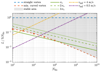
where is the mass of and is the dimensionless impact parameter. Two different approaches are considered below to estimate the collision velocity . The first is based on the speed ratio, defined as , where is the average beam velocity and is the translational temperature parallel to the beam [30, 31]. The dashed dotted lines in Figure S6 show the angular momentum resulting from droplet collisions at relative velocities of (yellow) and (purple), which were calculated from the speed ratios reported in Ref. [30]. From these calculations, a stable vortex should have been generated for all sizes relevant to the present experiment, while more than one vortex is predicted for atoms. This is not in agreement with our observations. At , a single curved vortex is mostly observed; a trend which continues for larger droplets. On top of using a pinhole nozzle, the maximum speed ratios (minimum relative velocity) reported in Ref. [30] are limited by the resolution of the instrument and may be considerably underestimated. Furthermore, we like to point out that the clusters in Ref. [30] are orders of magnitude smaller than the droplets in our experiment and we expect that the relative velocities will decrease with increased size. The speed ratio is expected to increase with nozzle diameter [32] and should be much larger for the conical nozzle used in the present experiment. Hence, an alternative expression is derived.
In the process of creating helium droplets in a supersonic jet, a pre-cooled gas is expanded through a nozzle, causing adiabatic cooling [30, 2]. Close to the nozzle throat, where high density prevails, droplets can grow by successive accumulation of single atoms or small clusters. The gas density decreases as it occupies more volume during expansions, and, at some point after expansion, growth by condensation ceases. However, a cluster can grow further by coagulation through a secondary collision process, as is known from other high pressure supersonic jet sources [33, 34]. Here, we assume a simple probabilistic model for growth by successive coagulation to estimate the collision velocities of these clusters.
The velocity of supersonic jets is typically described by a combination of two Maxwellian distributions with a perpendicular and a parallel component. The former mainly leads to a reduction of beam flux and is only relevant in the gas condensation region [35], whereas, the latter remains germane for estimating the angular momentum acquired during droplet growth from collision and coagulation. The parallel velocity component has a Gaussian shape
| (S5) |
in which is the temperature parallel to the beam, and, in the inertial frame of the expanding gas, , where corresponds to the average beam velocity [35]. Using and normalizing the equation above, the momentum probability density function of the atomic gas is given as
| (S6) |
with the standard deviation given by . The velocity spread was estimated assuming that the beam temperature during the coagulation process , which is the geometric mean between the terminal droplet temperature of () [36, 10] and the temperature where the isentropes cross the vapor pressure curve () [30, 10].
Assuming a model where each droplet consisting of atoms is produced from collisions of equally-sized droplets, i.e., , and with an initial momentum distribution given in Eq. (S6), the momentum distribution after an arbitrary number of collisions may be estimated from the convolution of the momentum distribution of collisions with itself
| (S7) |
from which follows that . This model rests on the fact that large clusters/droplets generated in the gas phase regime grow largely by coagulation [33, 37, 38]. The width of the distributions after collisions is
| (S8) |
This equation implies that collisional velocities decrease upon successive collisions, which is equivalent to a size-independent translational temperature and to the mass-dependent relative velocity . Within a translational freezing model for an average droplet size estimation, Ref. [30] also assumed a size-independent translational temperature. Considering the standard deviation as an estimate of the relative velocity between two droplets containing atoms each,
| (S9) |
which yields collision velocities of , , and for , and , respectively. While the assumption that equally-sized droplets coagulate is certainly a simplification, we expect Eq. (S9) to remain applicable even for the coagulation of differently-sized droplets since the size-dependent velocity originates from momentum conservation. These estimated collision velocities are much smaller than those estimated from the measured speed ratios discussed above 111The model is certainly based on simplifications and assumptions, the details of growth in the initial phase, the role of evaporation due to the heat of condensation and when the transition from growth by monomer addition to coagulation occurs are not explicitly considered. However, we would like to point out that the translational temperature of clusters grown out of the gas phase can be estimated from Ref. [30] (peak 2) and using the known scaling laws for cluster sizes [2, 65, 53] to the very low values in the range of . These low values seem reasonable because the clusters are only very loosely bound at the onset of condensation, and very small relative velocities and translational temperatures are required to generate them, thus suggesting that the relative collisional velocities tend to be even smaller estimated in our model above.. Substituting Eq. (S9), as obtained from our model, into Eq. (S4), the angular momentum expression as a result of droplet collisions is approximately given as
| (S10) |
The results of this estimation are shown for , and in Fig. S6 in solid, dashed and dotted dashed green, respectively. These values reflect the width of the velocity distribution, which is centered around zero.
From these considerations, it is very unlikely to create a straight vortex from a single collision at low relative velocities. At the same time, the probability for creating a stable single curved vortex increases with droplet size, predicting that more than of collisions induce sufficient angular momentum for , which is in reasonable agreement with our observation. It must be noted that the extrapolation of curved vortex stability to larger droplets, as done in Fig. S6, must be taken with caution. Only ripplon excitations were considered in Ref. [28]; a consideration that suffices for droplets with because phonons are not thermally excited at for those sizes. For the droplet sizes presented here, phonons might already play an essential role in the storage of angular momentum and could bend the lower bound of a stable curved vortex upward to higher values (red dashed line in Fig. S6), especially considering that phonon emission is a dissipative channel for the decay of vortices at low temperatures [40, 41, 42]. Another aspect that has not been discussed up to now is that coagulation will heat up the droplet, followed by evaporative cooling. This process reduces the droplet size and may also reduce the angular momentum of the droplet [43]. Nonetheless, Fig. S6 can give us an idea about vortex stability conditions, especially for , where the majority of excitations are ripplons, see Fig. 8.1 in Ref. [7].
IV Generation of Helium Droplets Using Different Nozzles
The nozzle stagnation conditions define the thermodynamic states (enthalpy and entropy) of the expanding fluid. For the generation of superfluid helium nanodroplets, different regimes are identified depending on which side of the saturation vapor curve the fluid would cross in an adiabatic isentropic expansion [30, 31, 44, 10, 45]. Stagnation conditions crossing from the gas phase are grouped under the gas condensation regime, while those crossing from the liquid phase are under liquid fragmentation.
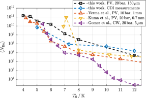
In many molecular beam setups for the generation of helium droplets, the use of a pinhole nozzle is standard, and its operation and performance are known [30, 10, 6, 45]; for a recent schematic of this pinhole nozzle, see Fig. S1 in the supplementary material of Ref. [49]. Figure S7 shows the average droplet sizes from a pinhole nozzle measured employing the ”titration” technique described in Ref. [6]. Small droplets containing roughly atoms are generated from gas condensation (), while larger droplets with more than atoms are produced from the liquid fragmentation () regime [10, 45, 6]. As revealed by x-ray coherent diffractive imaging experiments, a significant fraction () of these larger droplets have greater than [21, 22] and are likely studded with quantum vortices [20, 25]. Therefore, experiments wanting to image vortex-free droplets and the nanostructures assembled in them must obviate the use of pinhole nozzles while keeping in mind the droplet size range that still permits size determination from a diffraction image. Current limitations to x-ray imaging geometry constraint this range within up to [50].
Droplets generated from the gas condensation regime are likely vortex-free since their creation involves many statistical processes from the expanding cold helium gas. As such, they are less likely to acquire angular momentum from the shear forces introduced by the co-flowing helium, which is in contrast to those generated from the liquid fragmentation regime. Nonetheless, nucleation of quantum vortices remains feasible from droplet collision and coagulation, see the discussion in the preceding section and those in Refs. [28, 29].
Following known scaling laws, particularly for rare-gas clusters [2, 3, 51, 52, 53], large clusters or droplets can be generated from the gas condensation regime by enlarging the nozzle diameter or by shaping the nozzle channel (conical, trumpet, de Laval) such that the outflowing fluid is confined to a small angle with respect to the axial flow direction, concentrating the on-axis beam intensity. Ref. [54] presents a Direct Simulation Monte Carlo (DSMC) calculation of axisymmetric flow at a low stagnation pressure of for three types of nozzles: sonic, which is similar to the pinhole nozzle; conical-shaped; and trumpet-shaped. Shaping the flow effectively slows down the expansion process and increases the rate of collisions that promotes cluster growth through condensation and coagulation [2, 3, 54]; this effect is similar to the ”ripening” process described in Ref. [47]. In contrast, expansion from a smaller pinhole nozzle is faster, which stunts cluster growth [2, 54]; hence, only smaller clusters are created. This effect is demonstrated in Fig. S7 where the measured droplets sizes in the gas condensation regime vary by two to three orders of magnitudes between the pinhole and conical nozzles. We note that the measured average droplet of , generated using our conical nozzle at stagnation conditions of 20 bar and 10 K, is in accordance with that predicted by scaling laws used in cluster generation, where large clusters are generated through coagulation from the expansion of cold gas.
Since the equivalent nozzle diameter for shaped-nozzles can be several hundreds of times larger than pinhole nozzles [2, 3, 4], they are operated in tandem with pulse valves to prevent inundating the capacity of turbomolecular pumps and to maintain low background pressure. Ideally, pulsed nozzles should reach continuous flow conditions at longer valve opening times [55, 56, 54], as was done in this experiment. In many cases, however, the opening and closing of the valve is affected by the phase of outflowing fluid (which for some stagnation conditions may be a combination of gas and liquid) that could lead to complicated droplet beam profile [54]. To date, pulsed conical- [57, 58, 46, 47] and trumpet-shaped [59, 60, 61] nozzles have been used for generating larger helium droplets in the gas condensation regime; both with increasing use in a variety of contemporary experiments.
The trumpet-shaped nozzle attached to an Even-Lavie valve [59, 54] has already been used in earlier coherent diffractive imaging experiments [62, 63], see Refs. [59, 54] for the schematic of the Even-Lavie valve with a trumpet-shaped nozzle. Note that the stagnation condition used in operating the Even-Lavie valve for these imaging experiments follows an isentropic expansion trajectory that crosses the saturation vapor curve from the liquid phase; , is isentropic to , [64]. High stagnation pressures (or high flow velocities) are susceptible to turbulence, and the droplets are likely to acquire vorticity from the turbulent flow, enough to nucleate multiple vortices and distort the droplet shape. A similar effect was observed for the conical nozzle used in this experiment. For instance, no vortex structures were be observed at and , but increasing to at the same , xenon-traced vortices become prominent in the data set, see examples shown in Fig. S8.
Overall, the shape of the nozzle is an additional parameter for controlling the condensation process, which in turn facilitates the generation of large droplets with atoms from the gas condensation regime. Additionally, since these large droplets are likely formed stochastically through collision with other helium droplets at some distance away from the nozzle that may preclude the acquisition of angular momentum from shear forces induced by the co-flowing helium fluid, these large droplets acquire less angular momentum. Nevertheless, in order to ascertain which type of nozzle favors the creation of large vortex-free droplets, further imaging experiments using different kinds of nozzles are needed.
References
- Mazza et al. [2023] T. Mazza, T. M. Baumann, R. Boll, A. De Fanis, P. Grychtol, M. Ilchen, J. Montaño, V. Music, Y. Ovcharenko, N. Rennhack, D. E. Rivas, A. Rörig, P. Schmidt, S. Usenko, P. Ziołkowski, D. La Civita, M. Vannoni, H. Sinn, B. Keitel, E. Plönjes, U. F. Jastrow, A. Sorokin, K. Tiedtke, K. Mann, B. Schäfer, N. Breckwoldt, S.-k. Son, and M. Meyer, The beam transport system for the small quantum systems instrument at the European XFEL: Optical layout and first commissioning results, Journal of Synchrotron Radiation 30, 1 (2023).
- Hagena and Obert [1972] O. F. Hagena and W. Obert, Cluster formation in expanding supersonic jets: Effect of pressure, temperature, nozzle size, and test gas, The Journal of Chemical Physics 56, 1793 (1972).
- Hagena [1981] O. F. Hagena, Nucleation and growth of clusters in expanding nozzle flows, Surface Science 106, 101 (1981).
- Knuth [1997] E. L. Knuth, Size correlations for condensation clusters produced in free-jet expansions, The Journal of Chemical Physics 107, 9125 (1997).
- Kuster et al. [2021] M. Kuster, K. Ahmed, K.-E. Ballak, C. Danilevski, M. Ekmedžić, B. Fernandes, P. Gessler, R. Hartmann, S. Hauf, P. Holl, M. Meyer, J. Montaño, A. Münnich, Y. Ovcharenko, N. Rennhack, T. Rüter, D. Rupp, D. Schlosser, K. Setoodehnia, R. Schmitt, L. Strüder, R. M. P. Tanyag, A. Ulmer, and H. Yousef, The 1-megapixel pnCCD detector for the small quantum systems instrument at the European XFEL: System and operation aspects, Journal of Synchrotron Radiation 28, 576 (2021).
- Gomez et al. [2011] L. F. Gomez, E. Loginov, R. Sliter, and A. F. Vilesov, Sizes of large He droplets, The Journal of Chemical Physics 135, 154201 (2011).
- Tanyag et al. [2018] R. M. P. Tanyag, C. F. Jones, C. Bernando, S. M. O. O’Connell, D. Verma, and A. F. Vilesov, CHAPTER 8 Experiments with Large Superfluid Helium Nanodroplets, in Cold Chemistry: Molecular Scattering and Reactivity Near Absolute Zero, edited by O. Dulieu and A. Osterwalder (The Royal Society of Chemistry, 2018) pp. 389–443.
- Tanyag et al. [2022a] R. M. P. Tanyag, B. Langbehn, T. Möller, and D. Rupp, X-Ray and XUV Imaging of Helium Nanodroplets, in Molecules in Superfluid Helium Nanodroplets: Spectroscopy, Structure, and Dynamics, edited by A. Slenczka and J. P. Toennies (Springer International Publishing, Cham, 2022) pp. 281–341.
- Hulst [1981] H. C. Hulst, Light Scattering by Small Particles (Dover Publications, Inc., 1981).
- Toennies and Vilesov [2004] J. P. Toennies and A. F. Vilesov, Superfluid helium droplets: A uniquely cold nanomatrix for molecules and molecular complexes, Angewandte Chemie - International Edition 43, 2622 (2004).
- Starodub et al. [2008] D. Starodub, P. Rez, G. Hembree, M. Howells, D. Shapiro, H. N. Chapman, P. Fromme, K. Schmidt, U. Weierstall, R. B. Doak, and J. C. H. Spence, Dose, exposure time and resolution in serial x-ray crystallography, Journal of Synchrotron Radiation 15, 62 (2008).
- Rose [1948] A. Rose, Television Pickup Tubes and the Problem of Vision (Academic Press, 1948) pp. 131–166.
- Chapman et al. [2006] H. N. Chapman, A. Barty, S. Marchesini, A. Noy, S. P. Hau-Riege, C. Cui, M. R. Howells, R. Rosen, H. He, J. C. H. Spence, U. Weierstall, T. Beetz, C. Jacobsen, and D. Shapiro, High-resolution ab initio three-dimensional x-ray diffraction microscopy, J. Opt. Soc. Am. A 23, 1179 (2006).
- Schropp and Schroer [2010] A. Schropp and C. G. Schroer, Dose requirements for resolving a given feature in an object by coherent x-ray diffraction imaging, New Journal of Physics 12, 035016 (2010).
- Brown and Scriven [1980] R. A. Brown and L. E. Scriven, The shape and stability of rotating liquid drops, Proceedings of the Royal Society of London. A. Mathematical and Physical Sciences 371, 331 (1980).
- Ancilotto et al. [2018] F. Ancilotto, M. Barranco, and M. Pi, Spinning superfluid nanodroplets, Phys. Rev. B 97, 184515 (2018).
- Pi et al. [2021] M. Pi, J. M. Escartín, F. Ancilotto, and M. Barranco, Coexistence of vortex arrays and surface capillary waves in spinning prolate superfluid nanodroplets, Phys. Rev. B 104, 094509 (2021).
- Tanyag et al. [2015] R. M. P. Tanyag, C. Bernando, C. F. Jones, C. Bacellar, K. R. Ferguson, D. Anielski, R. Boll, S. Carron, J. P. Cryan, L. Englert, S. W. Epp, B. Erk, L. Foucar, L. F. Gomez, R. Hartmann, D. M. Neumark, D. Rolles, B. Rudek, A. Rudenko, K. R. Siefermann, J. Ullrich, F. Weise, C. Bostedt, O. Gessner, and A. F. Vilesov, Communication: X-ray coherent diffractive imaging by immersion in nanodroplets, Structural Dynamics 2, 051102 (2015).
- Martin et al. [2012] A. V. Martin, F. Wang, N. D. Loh, T. Ekeberg, F. R. N. C. Maia, M. Hantke, G. van der Schot, C. Y. Hampton, R. G. Sierra, A. Aquila, S. Bajt, M. Barthelmess, C. Bostedt, J. D. Bozek, N. Coppola, S. W. Epp, B. Erk, H. Fleckenstein, L. Foucar, M. Frank, H. Graafsma, L. Gumprecht, A. Hartmann, R. Hartmann, G. Hauser, H. Hirsemann, P. Holl, S. Kassemeyer, N. Kimmel, M. Liang, L. Lomb, S. Marchesini, K. Nass, E. Pedersoli, C. Reich, D. Rolles, B. Rudek, A. Rudenko, J. Schulz, R. L. Shoeman, H. Soltau, D. Starodub, J. Steinbrener, F. Stellato, L. Strüder, J. Ullrich, G. Weidenspointner, T. A. White, C. B. Wunderer, A. Barty, I. Schlichting, M. J. Bogan, and H. N. Chapman, Noise-robust coherent diffractive imaging with a single diffraction pattern, Opt. Express 20, 16650 (2012).
- Gomez et al. [2014] L. F. Gomez, K. R. Ferguson, J. P. Cryan, C. Bacellar, R. M. P. Tanyag, C. Jones, S. Schorb, D. Anielski, A. Belkacem, C. Bernando, R. Boll, J. Bozek, S. Carron, G. Chen, T. Delmas, L. Englert, S. W. Epp, B. Erk, L. Foucar, R. Hartmann, A. Hexemer, M. Huth, J. Kwok, S. R. Leone, J. H. S. Ma, F. R. N. C. Maia, E. Malmerberg, S. Marchesini, D. M. Neumark, B. Poon, J. Prell, D. Rolles, B. Rudek, A. Rudenko, M. Seifrid, K. R. Siefermann, F. P. Sturm, M. Swiggers, J. Ullrich, F. Weise, P. Zwart, C. Bostedt, O. Gessner, and A. F. Vilesov, Shapes and vorticities of superfluid helium nanodroplets, Science 345, 906 (2014).
- Bernando et al. [2017] C. Bernando, R. M. P. Tanyag, C. Jones, C. Bacellar, M. Bucher, K. R. Ferguson, D. Rupp, M. P. Ziemkiewicz, L. F. Gomez, A. S. Chatterley, T. Gorkhover, M. Müller, J. Bozek, S. Carron, J. Kwok, S. L. Butler, T. Möller, C. Bostedt, O. Gessner, and A. F. Vilesov, Shapes of rotating superfluid helium nanodroplets, Phys. Rev. B 95, 064510 (2017).
- Tanyag [2018] R. M. P. Tanyag, Imaging superfluid helium droplets, PhD Thesis, University of Southern California (2018).
- Verma et al. [2020] D. Verma, S. M. O. O’Connell, A. J. Feinberg, S. Erukala, R. M. P. Tanyag, C. Bernando, W. Pang, C. A. Saladrigas, B. W. Toulson, M. Borgwardt, N. Shivaram, M.-F. Lin, A. Al Haddad, W. Jäger, C. Bostedt, P. Walter, O. Gessner, and A. F. Vilesov, Shapes of rotating normal fluid versus superfluid droplets in molecular beams, Phys. Rev. B 102, 014504 (2020).
- Seidel and Maris [1994] G. M. Seidel and H. J. Maris, Morphology of superfluid drops with angular momentum, Physica B: Condensed Matter 194-196, 577 (1994).
- O’Connell et al. [2020] S. M. O. O’Connell, R. M. P. Tanyag, D. Verma, C. Bernando, W. Pang, C. Bacellar, C. A. Saladrigas, J. Mahl, B. W. Toulson, Y. Kumagai, P. Walter, F. Ancilotto, M. Barranco, M. Pi, C. Bostedt, O. Gessner, and A. F. Vilesov, Angular momentum in rotating superfluid droplets, Phys. Rev. Lett. 124, 215301 (2020).
- Donnelly and Barenghi [1998] R. J. Donnelly and C. F. Barenghi, The observed properties of liquid helium at the saturated vapor pressure, Journal of Physical and Chemical Reference Data 27, 1217 (1998).
- Bauer et al. [1995] G. H. Bauer, R. J. Donnelly, and W. F. Vinen, Vortex configurations in a freely rotating superfluid drop, Journal of Low Temperature Physics 98, 47 (1995).
- Lehmann and Schmied [2003] K. K. Lehmann and R. Schmied, Energetics and possible formation and decay mechanisms of vortices in helium nanodroplets, Phys. Rev. B 68, 224520 (2003).
- Escartín et al. [2022] J. M. Escartín, F. Ancilotto, M. Barranco, and M. Pi, Merging of superfluid helium nanodroplets with vortices, Phys. Rev. B 105, 024511 (2022).
- Buchenau et al. [1990] H. Buchenau, E. L. Knuth, J. Northby, J. P. Toennies, and C. Winkler, Mass spectra and time‐of‐flight distributions of helium cluster beams, The Journal of Chemical Physics 92, 6875 (1990).
- Harms et al. [1997] J. Harms, J. P. Toennies, and E. L. Knuth, Droplets formed in helium free-jet expansions from states near the critical point, The Journal of Chemical Physics 106, 3348 (1997).
- Toennies and Winkelmann [1977] J. P. Toennies and K. Winkelmann, Theoretical studies of highly expanded free jets: Influence of quantum effects and a realistic intermolecular potential, The Journal of Chemical Physics 66, 3965 (1977).
- Soler et al. [1982] J. M. Soler, N. García, O. Echt, K. Sattler, and E. Recknagel, Microcluster growth: Transition from successive monomer addition to coagulation, Phys. Rev. Lett. 49, 1857 (1982).
- Rupp et al. [2012] D. Rupp, M. Adolph, T. Gorkhover, S. Schorb, D. Wolter, R. Hartmann, N. Kimmel, C. Reich, T. Feigl, A. R. B. de Castro, R. Treusch, L. Strüder, T. Möller, and C. Bostedt, Identification of twinned gas phase clusters by single-shot scattering with intense soft x-ray pulses, New Journal of Physics 14, 055016 (2012).
- Pauly [2000] H. Pauly, Atom, Molecule, and Cluster Beams I, 1st ed., Springer Series on Atomic, Optical, and Plasma Physics, Vol. 28 (Springer Berlin Heidelberg, Berlin, Heidelberg, 2000) p. 334.
- Hartmann et al. [1995] M. Hartmann, R. E. Miller, J. P. Toennies, and A. Vilesov, Rotationally resolved spectroscopy of S in liquid helium clusters: A molecular probe of cluster temperature, Phys. Rev. Lett. 75, 1566 (1995).
- Ratner [1999] M. A. Ratner, Kinetics of cluster growth in expanding rare-gas jet, Low Temperature Physics 25, 266 (1999).
- Jansen et al. [2011] R. Jansen, N. Gimelshein, S. Gimelshein, and I. Wysong, A Lagrangian–Eulerian approach to modeling homogeneous condensation in high density gas expansions, The Journal of Chemical Physics 134, 104105 (2011).
- Note [1] The model is certainly based on simplifications and assumptions, the details of growth in the initial phase, the role of evaporation due to the heat of condensation and when the transition from growth by monomer addition to coagulation occurs are not explicitly considered. However, we would like to point out that the translational temperature of clusters grown out of the gas phase can be estimated from Ref. [30] (peak 2) and using the known scaling laws for cluster sizes [2, 65, 53] to the very low values in the range of . These low values seem reasonable because the clusters are only very loosely bound at the onset of condensation, and very small relative velocities and translational temperatures are required to generate them, thus suggesting that the relative collisional velocities tend to be even smaller estimated in our model above.
- Paoletti and Lathrop [2011] M. S. Paoletti and D. P. Lathrop, Quantum turbulence, Annual Review of Condensed Matter Physics 2, 213 (2011).
- Harris et al. [2016] G. I. Harris, D. L. McAuslan, E. Sheridan, Y. Sachkou, C. Baker, and W. P. Bowen, Laser cooling and control of excitations in superfluid helium, Nature Physics 12, 788 (2016).
- Madeira et al. [2020] L. Madeira, M. Caracanhas, F. dos Santos, and V. Bagnato, Quantum turbulence in quantum gases, Annual Review of Condensed Matter Physics 11, 37 (2020).
- Lehmann and Dokter [2004] K. K. Lehmann and A. M. Dokter, Evaporative cooling of helium nanodroplets with angular momentum conservation, Physical Review Letters 92, 173401 (2004), 0312041 .
- Grisenti and Toennies [2003] R. E. Grisenti and J. P. Toennies, Cryogenic microjet source for orthotropic beams of ultralarge superfluid helium droplets, Phys. Rev. Lett. 90, 234501 (2003).
- Slenczka and Toennies [2022] A. Slenczka and J. P. Toennies, eds., Molecules in Superfluid Helium Nanodroplets: Spectroscopy, Structure, and Dynamics, Topics in Applied Physics, Vol. 145 (Springer International Publishing, Cham, 2022).
- Kuma and Azuma [2017] S. Kuma and T. Azuma, Pulsed beam of extremely large helium droplets, Cryogenics 88, 78 (2017).
- Verma and Vilesov [2018] D. Verma and A. F. Vilesov, Pulsed helium droplet beams, Chemical Physics Letters 694, 129 (2018).
- Behrens [2019] P. Behrens, Charakterisierung von gepulsten Clusterquellen, Master’s thesis, Technische Universität Berlin (2019).
- Tanyag et al. [2020] R. M. P. Tanyag, A. J. Feinberg, S. M. O. O’Connell, and A. F. Vilesov, Disintegration of diminutive liquid helium jets in vacuum, The Journal of Chemical Physics 152, 234306 (2020).
- Tanyag et al. [2022b] R. M. P. Tanyag, C. Bacellar, W. Pang, C. Bernando, L. F. Gomez, C. F. Jones, K. R. Ferguson, J. Kwok, D. Anielski, A. Belkacem, R. Boll, J. Bozek, S. Carron, G. Chen, T. Delmas, L. Englert, S. W. Epp, B. Erk, L. Foucar, R. Hartmann, A. Hexemer, M. Huth, S. R. Leone, J. H. Ma, S. Marchesini, D. M. Neumark, B. K. Poon, J. Prell, D. Rolles, B. Rudek, A. Rudenko, M. Seifrid, M. Swiggers, J. Ullrich, F. Weise, P. Zwart, C. Bostedt, O. Gessner, and A. F. Vilesov, Sizes of pure and doped helium droplets from single shot x-ray imaging, The Journal of Chemical Physics 156, 041102 (2022b).
- Wörmer et al. [1991] J. Wörmer, M. Joppien, G. Zimmerer, and T. Möller, Formation and confinement of Wannier excitons in free argon clusters, Phys. Rev. Lett. 67, 2053 (1991).
- Karnbach et al. [1993] R. Karnbach, M. Joppien, J. Stapelfeldt, J. Wörmer, and T. Möller, CLULU: An experimental setup for luminescence measurements on van der Waals clusters with synchrotron radiation, Review of Scientific Instruments 64, 2838 (1993).
- Dorchies et al. [2003] F. Dorchies, F. Blasco, T. Caillaud, J. Stevefelt, C. Stenz, A. S. Boldarev, and V. A. Gasilov, Spatial distribution of cluster size and density in supersonic jets as targets for intense laser pulses, Physical Review A 68, 23201 (2003).
- Even [2014] U. Even, Pulsed supersonic beams from high pressure source: Simulation, results, and experimental measurements, Advances in Chemistry 2014, 636042 (2014).
- Morse [1996] M. D. Morse, 2 - Supersonic Beam Sources, in Atomic, Molecular, and Optical Physics: Atoms and Molecules, Experimental Methods in the Physical Sciences, Vol. 29, edited by F. Dunning and R. G. Hulet (Academic Press, 1996) pp. 21–47.
- Christen [2013] W. Christen, Stationary flow conditions in pulsed supersonic beams, The Journal of Chemical Physics 139, 154202 (2013).
- Slipchenko et al. [2002] M. N. Slipchenko, S. Kuma, T. Momose, and A. F. Vilesov, Intense pulsed helium droplet beams, Review of Scientific Instruments 73, 3600 (2002).
- Yang et al. [2005] S. Yang, S. M. Brereton, and A. M. Ellis, Controlled growth of helium nanodroplets from a pulsed source, Review of Scientific Instruments 76, 104102 (2005).
- Pentlehner et al. [2009] D. Pentlehner, R. Riechers, B. Dick, A. Slenczka, U. Even, N. Lavie, R. Brown, and K. Luria, Rapidly pulsed helium droplet source, Review of Scientific Instruments 80, 043302 (2009).
- Katzy et al. [2016] R. Katzy, M. Singer, S. Izadnia, A. C. LaForge, and F. Stienkemeier, Doping He droplets by laser ablation with a pulsed supersonic jet source, Review of Scientific Instruments 87, 013105 (2016).
- Pandey et al. [2021] R. Pandey, S. Tran, J. Zhang, Y. Yao, and W. Kong, Bimodal velocity and size distributions of pulsed superfluid helium droplet beams, The Journal of Chemical Physics 154, 134303 (2021).
- Rupp et al. [2017] D. Rupp, N. Monserud, B. Langbehn, M. Sauppe, J. Zimmermann, Y. Ovcharenko, T. Möller, F. Frassetto, L. Poletto, A. Trabattoni, F. Calegari, M. Nisoli, K. Sander, C. Peltz, M. J. Vrakking, T. Fennel, and A. Rouzée, Coherent diffractive imaging of single helium nanodroplets with a high harmonic generation source, Nature Communications 8, 493 (2017).
- Langbehn et al. [2018] B. Langbehn, K. Sander, Y. Ovcharenko, C. Peltz, A. Clark, M. Coreno, R. Cucini, M. Drabbels, P. Finetti, M. Di Fraia, L. Giannessi, C. Grazioli, D. Iablonskyi, A. C. LaForge, T. Nishiyama, V. Oliver Álvarez de Lara, P. Piseri, O. Plekan, K. Ueda, J. Zimmermann, K. C. Prince, F. Stienkemeier, C. Callegari, T. Fennel, D. Rupp, and T. Möller, Three-dimensional shapes of spinning helium nanodroplets, Phys. Rev. Lett. 121, 255301 (2018).
- Mc Carty [1973] R. D. Mc Carty, Thermodynamic properties of helium 4 from 2 to 1500 K at pressures to Pa, Journal of Physical and Chemical Reference Data 2, 923 (1973).
- Hagena [1992] O. F. Hagena, Cluster ion sources (invited), Review of Scientific Instruments 63, 2374 (1992).