Enhanced Access Traffic Steering Splitting Switching with Utility-Based Decisioning ††thanks: This work is supported by the European Commission’s Horizon 2020 research and innovation program under grant agreement No 871428, 5G-CLARITY project. ††thanks: This article was authored by Tezcan Cogalan while he was associated with InterDigital. Tezcan is now working at Samsung Research UK.
Abstract
Coexistence of 3GPP access networks, namely 4G and 5G, and non-3GPP access networks, namely Wi-Fi, has enabled data offloading from one access network to another to reduce burden on the congested network. Within the evolution of 5G system, the coexistence has been evolved to a multi-access framework where simultaneous transmission on both 3GPP and non-3GPP access networks has been enabled. This framework is named as ATSSS in 3GPP and is considered as one of the key enablers to provide stringent requirements on data rate and service continuity. In this paper, we introduce an enhanced ATSSS (eAT3S) algorithm where not only instantaneous link performance measurements but also network operator preferences are taken into account to optimize the overall network performance. As part of considered non-3GPP wireless access technologies (WATs), light fidelity (LiFi) access networks are also considered alongside with Wi-Fi networks.
Index Terms:
5G-Advanced, 5GNR, Wi-Fi, LiFi, multi-connectivity, ATSSSI Introduction
Continuous increase on mobile data traffic usage globally has emerged in various reports over the past ten years. In one of the recent reports [1], it is predicted that by 2026, 5G networks will carry more than half of the world’s smartphone traffic. While this estimation is given based on global mobile network data traffic, the data traffic generated by Wi-Fi devices is excluded. The same report also notes that the majority of mobile traffic in urban deployments is generated by indoor users. The huge demand for mobile data traffic in the near future can be justified by ongoing digital transformation from small businesses to large ones. One recent obvious example has been seen on Industry 4.0 transformation where it has paved the way for industries to define use cases with stringent requirements for not only data rate but also latency, reliability and service continuity [2]. Another example to note is the demand on immersive experiences where both high data rates and low latency should be achieved mostly on indoor environments.
As the bandwidth, a.k.a resource, is finite and expensive, efficient use of all available resources is the key optimization objective for mobile network operators. Therefore, it is important that different wireless access technologies (WATs) should coexist and complement each other [3]. From this perspective, integrating 4G/5G networks, also known as 3GPP networks, with Wi-Fi networks, also named as a non-3GPP network, has been studied in various releases of the 3GPP system. Initially, the integration is used to utilize one WAT at a time. With the evolution of the 5G system, the integration of 3GPP and non-3GPP access networks has enabled a multi-access framework where simultaneous transmission on both 3GPP and non-3GPP access networks becomes possible. In 3GPP, this multi-access framework is named as access traffic steering, splitting and switching (ATSSS) [4, 5, 6]. As its name states, the framework has enabled switching, splitting and steering of the access traffic onto 3GPP and non-3GPP networks.
ATSSS framework enforces access traffic steering, splitting and switching strategies in the user plane function (UPF) and in the user equipment (UE). For example, a given traffic steering rule (the steering rule term is used to represent steering, splitting and switching modes) may assign a fraction of ongoing traffic onto the 3GPP network and the rest of the traffic to the non-3GPP network. Another example can be an assignment of a priority indicator for one of the access networks to consider it as the first option to steer traffic flows.
ATSSS has been studied in 3GPP in three phases, namely, Release 16, Release 17 and Release 18, as detailed in Section II. In Release 16 ATSSS [4], a total of four steering modes were defined. In Release 17 ATSSS [5], a new steering mode called autonomous steering mode is defined. In this steering mode, the UE and the UPF can freely and independently decide how to split the traffic across the two accesses. Release 18 ATSSS [6] has been studying objectives like how to support redundant traffic steering which replicates the packets (for both guaranteed bit rate (GBR) and non-GBR traffic) on both accesses and how the traffic can be switched between two non-3GPP access paths in the same operator network in a way to enhance the ATSSS feature.
In the Release 16 ATSSS [4] workflow, the UE and UPF cannot flexibly distribute the traffic over 3GPP and non-3GPP accesses according to real-time link status. In other words, the traffic distribution is based on a pre-determined weight factor which is provided by the network operator as a policy control function (PCF) rule. In Release 17 ATSSS [5], as noted, a new autonomous steering mode is proposed as a solution for the noted problem. The working principle of this mode is as follows: (i) the PCF/session management function (SMF) either does not send a pre-determined weight factor or sends an initial weight factor, and (ii) the UE and the UPF dynamically adjust the weight factor for each access on uplink and downlink, respectively. Such a procedure has the following drawbacks. First, there is no way for the network operators to simultaneously incorporate their preferences that may reflect their charging policies or service level agreements (SLAs) and to enable the user plane optimization that the autonomous steering mode can achieve. Second, as the UE and UPF use performance measurements on round trip time (RTT), uplink (UL)/downlink (DL) maximum packet loss rate, UL/DL maximum jitter as well as UE ’s internal state (e.g., battery level) to adjust the weight factor dynamically, the performance measurements may change from one epoch to another due to increase/decrease of the traffic load on both accesses. Thus, there can be situations where the weight factors of the different accesses change frequently leading to a ping-pong effect i.e., increasing the weight factor in one epoch and decreasing it in the next epoch.
A solution to overcome the noted first drawback may consider, firstly, the weight factors adjustment by an implementation specific amount [5] (stepwise increase/decrease) when one of the access’ link is not within a configured thresholds of a parameter such as signal power. Then, once both accesses are considered as valid (means within the considered thresholds), the weight factors are re-adjusted to the one indicated by the PCF. Although, such a solution may prevent too much divergence from the rules indicated by the PCF, it does not mean that it guarantees a convergence to the PCF rules/weight factor. Also, the proposed stepwise increase/decrease approach either (i) will not provide a full flexibility for the UE and the UPF as it considers the scenario where only one of the accesses is valid; or (ii) will suffer from the noted ping-pong effect.
As noted in the second drawback, the UE and UPF decide on the weight factors based on the combination of the current (real-time) link status and the thresholds for several measurements. However, there is no mechanism defined for the UE and UPF to either improve the overall network performance for a local area of interest that will take into account operator’s preferences or SLA s.
This paper proposes an enhanced ATSSS (eAT3S) framework that uses a utility-based approach where both the instantaneous link conditions, access network status as well as operator’s preference are taken into account. The motivation behind introducing such an enhancement is to mitigate the noted drawbacks of the current ATSSS in the 3GPP system. Moreover, in this paper, IEEE 802.11 based light fidelity (LiFi) network which is an indoor optical wireless communication system [7, 8, 9] is considered as part of an integrated non-3GPP access network along with Wi-Fi. Also, the considered underlying system is based on the 5G-CLARITY system described in [9, Fig.1]111Due to page limitation, a detailed description of the system architecture is omitted in this paper. This paper focuses on ATSSS algorithm and its performance evaluation. Hence, interested readers are referred to [9] for further details on the system architecture..
The rest of the paper is organized as follows. Section II provides details of 3GPP ATSSS framework in various releases. Section III introduces considered architecture focusing on the multi-connectivity and our defined eAT3S algorithm. Section IV describes the considered simulation scenario and presents the evaluation results of the proposed eAT3S framework. Finally, Section V concludes the paper.
II ATSSS
In Release 16 ATSSS [4], a total of four steering modes were defined. For active-standby, all traffic of the multi-access protocol data unit (PDU) (MA-PDU) session is sent to one access only, which is called the “active” access. The other access serves as a “standby” access and takes traffic only when the active access becomes unavailable. For smallest delay, the high priority access is the one that can provide the smallest RTT performance. Performance measurement function (PMF) can be used to determine the latency of each access link or alternatively multi-path TCP (MPTCP) can be used to obtain such latency measurements. For static Load-Balancing, a weight information element is used to indicate the proportion of the traffic to be forwarded to 3GPP and non-3GPP access networks. This mode is only applicable to non-GBR quality of service (QoS) flow. For priority-based, the two accesses are assigned a priority, and all traffic of the MA-PDU session is sent to the high priority access. When congestion arises on the high priority access, new data flows (the “overflow” traffic) are sent to the low priority access. Also, when the high priority access becomes suddenly unavailable, all traffic is forwarded to the other access (low priority). Note should be taken that the definition of a congested link is implementation specific.
Release 17 ATSSS [5] introduced a new steering mode called autonomous steering mode where the UE and the UPF can freely and independently decide how to split the traffic across the two accesses when load-balancing steering mode is in use. For all steering modes, the network may provide a UE-assistance indication, which indicates that (a) the UE can decide how to distribute the UL traffic based on its internal state (e.g. battery level), and (b) the UE can request from UPF to apply the same distribution for the DL traffic, and the UPF can take the UE’s request into account when deciding the DL transmission traffic distribution. For all steering modes, the UE requests from UPF to apply the same distribution for the DL traffic by using the PMF protocol, if available, or another mechanism, if the PMF protocol is not available. This other mechanism will be determined during the normative phase of the work. For the Load-Balancing steering mode with fixed weights and Priority-based steering mode, it can be possible to apply a threshold condition, which indicates whether a measured parameter is above or below a threshold. The measured parameter in a threshold condition may include (a) the RTT and (b) the packet loss rate. Also, the threshold conditions will be the same for both 3GPP and non-3GPP accesses since QoS requirements are per service.
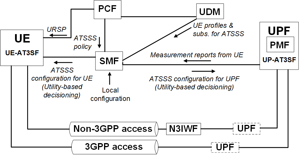
The overall ATSSS execution procedure is depicted in Fig. 1 and can be summarized as follows. First, PCF defines an ATSSS policy based on information from unified data management (UDM) such as the UE profiles and subscriptions, and then sends ATSSS policy to SMF. Secondly, the ATSSS policy is configured at the UE, more specifically UE-AT3SF where AT3SF stands for ATSSS function and SMF. Then, SMF generates AT3S rules based on the PCF’s policy and pushes ATSSS rules for downlink traffic to UPF and ATSSS rules for uplink traffic to UE. Then, UPF executes the ATSSS rule and when downlink data arrives, the UPF determines the appropriate access path(s) based on the given ATSSS rule and sends the downlink data to the UE. PMF performs the path performance measurement for each access path between the UE and UPF, and reports them to SMF. Based on performance measurement results provided by PMF, the SMF updates the ATSSS rules and configures updated rules to UE and UPF. Although 3GPP does not mandate the specific implementation of the ATSSS steering function, it allows for different options such as MPTCP [10] used in 5G-CLARITY project [9].
The traffic steering strategies enforced via ATSSS rules are based on predefined values for either all traffic types or some specific traffic type such as UDP or TCP to a specific IP address or port. For example, if the load balancing steering mode is selected, a predefined percentage value has to be written for 3GPP and non-3GPP access networks, such as 20 for 3GPP and 80 for non-3GPP. In another example, the priority-based steering mode can be selected to prevent congestion over 3GPP network. Then, high priority is assigned to non-3GPP network to offload the 3GPP network traffic. All these rules are pre-constructed and ordered in a way that as long as a data flow matches a rule, the data flow gets routed according to this rule and the remaining rules are not considered. While traffic is routed according to a specific rule, sudden changes on the network status such as link availability due to channel state fluctuations or link blockage will not be incorporated to traffic routing.
III eAT3S system architecture and algorithm definition
The 5G-CLARITY system architecture includes virtualized network and application functions (VNFs/VAFs) that can be executed atop the infrastructure including compute, storage and networking fabric. The VNFs implement 3GPP functions, virtual Radio Access Network (vRAN), 5G Core and UPF; and provide means to support integration of non-3GPP WATs. The VAFs on the other hand, allow providing domain-specific telemetry services such as vRAN telemetry, access network telemetry; and open RAN (O-RAN) xApps and service applications.
The 5G-CLARITY architecture considers an integration of Wi-Fi and LiFi access networks to 5G network via non-3GPP interworking function (N3IWF). In 5G-CLARITY, although both Wi-Fi and LiFi networks connect to the same N3IWF, each network maps to a different IP subnetwork. Thus, it is enabled that separate IP interfaces for Wi-Fi, LiFi and 5G can be managed by MPTCP as different paths.
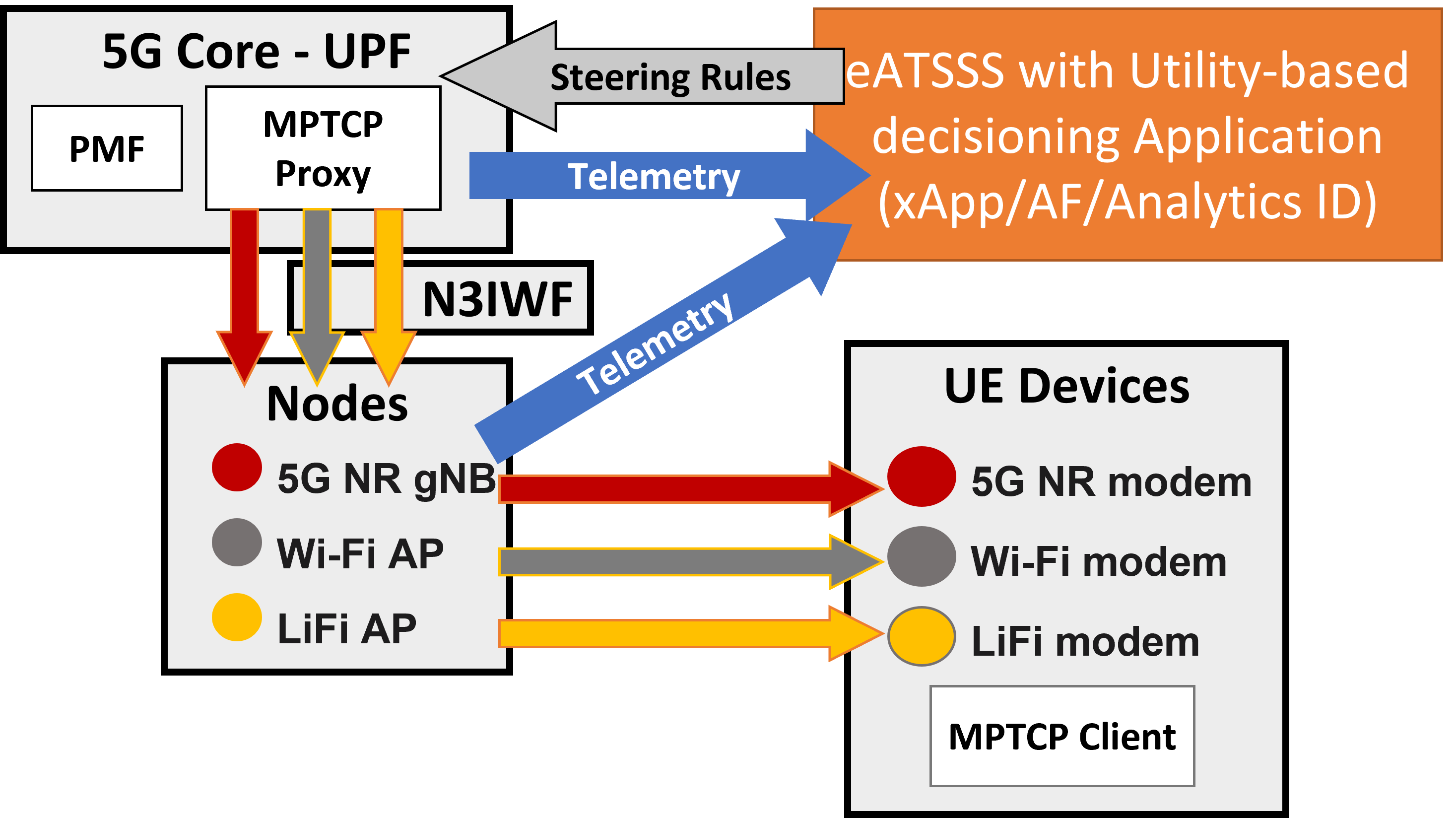
In Fig. 2, eAT3S execution and interaction between network entities are shown. It is worth to note that the flow regarding PCF, SMF and UPF in Fig. 1 also exists where ATSSS rules including operator preference are available at the eAT3S with utility-based decisioning application. As it is shown in the figure, the eAT3S framework can be implemented as an O-RAN xApp, an application function or an analytics as part of 3GPP analytics network function, called network data analytics function (NWDAF).
III-A eATSSS algorithm
In the proposed utility-based eAT3S algorithm, user traffic types are taken into account to both decide on the steering mode selection such as load balancing (LB) or smallest delay (SD) as well as utility function weights. In other words, based on the user requested traffic type, the algorithm decides the steering mode to be used, where different threshold levels are used to identify the satisfaction of various parameters. The threshold levels can be defined by network operator in a static or variable way. More specifically, if eMBB traffic is requested, the LB steering mode will be chosen with a set of specific threshold weights for signal strength, 5G base station (gNB)/access point (AP) buffer status, signal-to-interference-plus-noise ratio (SINR) and transmission delay, to decide the assigned load level on 3GPP and non-3GPP access networks. In case, URLLC traffic is requested, SD mode will be applied with a specific set of threshold weights for the same parameters to decide what access networks out of all available networks should be used to duplicate (or triple if all accesses achieve the utility threshold) the traffic.
The motivation of using a utility-based algorithm is to unify the steering weight parameters for different service/traffic types and improve the overall network performance. In this paper, a logarithmic utility function in (1) is used for both eMBB and URLLC traffic types [11]. In (1), is the telemetry data, namely, SINR, buffer or transmission delay; represents the WAT, namely, 5G, Wi-Fi or LiFi; is the utility for a given parameter and WAT for an active user ; is the user’s measured network-specific telemetry data; and is the maximum value considered for a given network-specific telemetry data. The utility in (1) is constructed in a way that and . For an eMBB traffic, although the main key performance indicator (KPI) is throughput, transmission delay and buffer status would have impact on the achieved rate when multiple users in the system are competing for the same resources. It is also the same for a URLLC traffic where the main KPI is latency and reliability but throughput and buffer status are also important to provide the latency and reliability requirements for a multi-user scenario. Therefore, in the proposed utility-based eAT3S algorithm, the weights of SINR (), gNB/AP buffer status () and transmission delay () are considered as the weights that can be defined by network operators and can have different values for LB and SD steering modes. Moreover, as each of these parameters would have an impact on the overall performance, an WAT that cannot achieve a performance higher than a predefined threshold of , and for SINR, buffer status and delay, respectively, is not considered in the utility calculation ().
| (1) |
Once the utility of each parameter is obtained for each WAT, the overall utility is obtained as:
| (2) |
as higher buffer and delay performance would degrade the overall utility. Then, the weight factor assignment for each user for each WAT, , is obtained as a percentage on each WAT for LB in step 12 or a selection of a set of WATs for SD steering mode in step 17 in Algorithm 1. The execution flow of the proposed eAT3S algorithm is provided in Algorithm 1.
IV Performance Evaluation
IV-A Scenario description
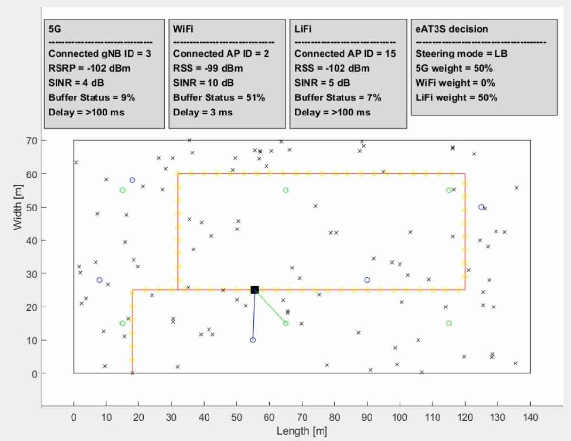
In order to evaluate the performance of the proposed utility-based eAT3S algorithm, an Industry 4.0 scenario based on a real factory layout, depicted in Fig. 3 is chosen. The considered scenario is aligned with a use case defined in the 5G-CLARITY project [12]. The scenario includes the deployment of three different WATs; Wi-Fi at 5 GHz, LiFi at 337 THz and 5G new radio (5GNR) at 3.5 GHz. The Wi-Fi, LiFi and 5GNR systems use the channel bandwidth values of , and MHz, respectively. In the simulation scenario, an automated guided vehicle (AGV) that follows the path shown in red in the figure and 100 other users randomly distributed in the considered factory environment exist. The randomly distributed 100 users are considered as static users that include factory workers, connected production machinery and sensors. Along the AGV’s path, each WAT has a different level of coverage and provides different signal levels from various access nodes. In the simulation environment shown in Fig. 3, there are six 5G NR gNBs (shown by green circles) deployed based on factory scenario defined in TR 38.901 [13], five Wi-Fi APs (shown by blue circles), and LiFi APs (shown by yellow circles along the AGV’s path) deployed with a inter-site distance of 3 meters along the AGV’s predefined path. In simulations, all users are equipped with a UE or customer-premises equipment (CPE) that provides network connectivity to the all three WATs. With the aid of mobility of the AGV (with a speed of m/s) and other users that are modeled with a Poisson probabilistic traffic arrivals defined in Section IV-B as well as a random spatial traffic distribution based on a Zipf popularity distribution defined in Section IV-C, the proposed eAT3S algorithm is evaluated in a realistic environment.
IV-B Poisson Traffic Model
The UE requests are modeled as a Poisson arrival process where the sequence of inter-arrival times for UE requests are independent and identically distributed (i.i.d) random variables. The Poisson distribution probability mass function of a number of requests/events in a given time interval is given as:
| (3) |
where is the Poisson distribution parameter, which is also known as the average number of requests/events during a unit of time; and is the factorial operation. In the considered system model, a randomly selected UE is activated in each Poisson-based request arrival event, and a content is requested based on the considered Zipf content popularity distribution .
IV-C Requested content details
To enable a random spatial traffic distribution among the deployed APs/gNBs to mimic more realistic network deployment, different content sizes, different popularities among available contents and Poisson arrival process for UE requests are considered.
Regarding the content popularity, the popularity within the library of files is characterized as a Zipf distribution [14, 15]. Therefore, the probability of a file being requested can be written as:
| (4) |
where is the Zipf parameter that characterizes the probability of content reuse; and is a constant for a given number of files in the library and . When is chosen as a value larger than zero, the most popular contents have a lot higher chance to be requested. The content popularity distribution is only used to decide what content should be considered for a given user request
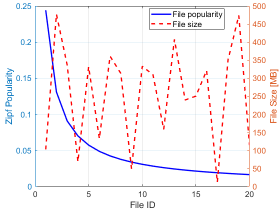
In addition to content popularity distribution, a random distribution is considered for the file size. This is independent from the content popularity. Each file in the library of files has a randomly allocated file size as shown in Fig. 4.
IV-D Multi-connectivity evaluation
Fig. 3 shows an instance from a custom system level simulator that mimics the factory environment defined in D5.1 [12]. While the AGV moves along the path, the system level simulator provides telemetry readings such as AGV’s connected access node, its received signal power, SINR, access node’s buffer status for the downlink traffic and UE-specific transmission delay measurements from all three WATs. The proposed eAT3S algorithm makes use of the available telemetry data. The used scheduling type and allocated weight information is also captured in Fig. 3. For the LB steering mode, the steering score weights of SINR (), gNB/AP buffer status () and transmission delay () are set to 1, 0.7 and 0.2, respectively. For the SD steering mode, , and are set to 0.5, 0.2 and 1, respectively. Therefore, it can be expected that for the same telemetry readings for the considered parameters, the utility assessment would be different. For example, for the given instance in the figure, the utility metric of the LB is different from the SD. In the considered instance, Wi-Fi access is not considered for the LB due to mainly its buffer status. However, it may be considered for the SD as it has the minimum delay performance among the available WATs. Hence, weight allocation and WAT selection can differ for each steering mode, depending on the operator’s preference on the steering scoring weights as well as threshold value to consider any of the WAT as a candidate for steering decisions.
Fig. 5 shows a comparison of 5G SINR, weight assignment and utility score for the LB steering mode for the whole journey of the AGV when a normalized threshold value of is used for all measurement parameters. The AGV’s traffic is considered as eMBB. The figure shows that the utility scoring of the LB steering mode mostly follows the SINR performance as shown at , , and . This is due to in the utility scoring. The figure also shows that on some occasions, having a good SINR performance is not enough to steer traffic onto the WAT. For example, for a period from 3000s to 3500s, although the SINR changes from 0 dB to 10 dB, the utility score is not high enough. Hence, the LB steering mode does not steer any traffic onto 5G during that period.
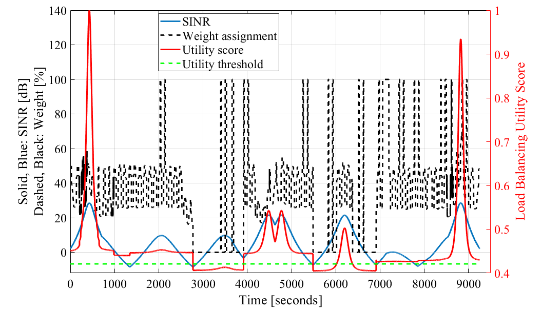
Table I compares the decisioning of both steering modes for the same AGV position. It is worth to note that, although the radio conditions/telemetry is the same for different simulation runs with different traffic type requested by the AGV (eMBB for LB and URLLC for SD), the buffer status and transmission delay performance are different. This is due to the Poisson-based user request arrival as well as popularity-based content selection. In each run, the user requests and selected content are generated based on the described procedures. In the simulation time of 00:59, the LB steering mode divides the access traffic in two and assigns it to 5G and LiFi. However, at the same simulation time, at the same AGV position, the SD steering mode only selects Wi-Fi to transmit URLLC traffic as it achieves a transmission delay of 10ms whereas 5G and LiFi achieve 89ms and >100ms, respectively. Moreover, although Wi-Fi achieves a higher SINR performance compared to 5G and LiFi for the same AGV position, its buffer status degrades the utility score of Wi-Fi and the LB steering mode discards Wi-Fi in the weight assignment decisioning. Similar conclusions can be derived for the other considered simulation times/AGV positions.
| Instance | Telemetry | LB | SD | ||||
| 5G | Wi-Fi | LiFi | 5G | Wi-Fi | LiFi | ||
| 1 | Cell ID | 1 | 1 | 4 | 1 | 1 | 4 |
| RSRP/RSS [dBm] | -77 | -101 | -100 | -77 | -101 | -100 | |
| SINR [dB] | 29 | 9 | 9 | 29 | 9 | 9 | |
| Buffer Status [%] | 8 | 27 | 8 | 17 | 64 | 8 | |
| Delay [ms] | 14 | 6 | 2 | 18 | 9 | 2 | |
| Weight [%]/Selection | 49 | 22 | 29 | 1 | 1 | 1 | |
| 2 | Cell ID | 3 | 2 | 15 | 3 | 2 | 15 |
| RSRP/RSS [dBm] | -102 | -99 | -102 | -102 | -99 | -102 | |
| SINR[dB] | 4 | 10 | 5 | 4 | 10 | 5 | |
| Buffer Status [%] | 9 | 51 | 7 | 14 | 65 | 8 | |
| Delay [ms] | >100 | 3 | >100 | 89 | 10 | >100 | |
| Weight [%]/Selection | 50 | 0 | 50 | 0 | 1 | 0 | |
| 3 | Cell ID | 6 | 4 | 37 | 6 | 4 | 37 |
| RSRP/RSS [dBm] | -90 | -79 | -100 | -90 | -79 | -100 | |
| SINR[dB] | 16 | 30 | 10 | 16 | 30 | 10 | |
| Buffer Status [%] | 10 | 68 | 10 | 21 | 100 | 7 | |
| Delay [ms] | 41 | 3 | 3 | 26 | 4 | 2 | |
| Weight [%]/Selection | 23 | 48 | 28 | 0 | 1 | 1 | |
V Conclusions
It is shown that our proposed eAT3S algorithm enables the inclusion of multiple network parameters in the steering decisioning. It enables private/public network operators to derive user or environment specific network policy configurations to efficiently utilize 3GPP and non-3GPP networks. The structure of the proposed utility-based eAT3S algorithm also enables an inclusion of machine learning-based approaches that may predict the performance of different network parameters and proactively update the steering weights/WAT selections to further improve the user QoS/QoE. We leave the definition of machine learning-based eAT3S policies as future work.
References
- [1] “Ericsson Mobility Report,” White Paper, Ericsson, Jun. 2021.
- [2] J. Navarro-Ortiz et al., “A Survey on 5G Usage Scenarios and Traffic Models,” in IEEE Commun. Surveys Tuts., vol. 22, no. 2, pp. 905–929, Dec. 2020.
- [3] B. Jin et al., “Aggregating LTE and Wi-Fi: Toward Intra-Cell Fairness and High TCP Performance,” in IEEE Trans. Veh. Technol., vol. 16, no. 10, pp. 6295–-6308, 2017.
- [4] 3GPP TR 23.793 “Study on Access Traffic Steering, Switch and Splitting Support in the 5G System Architecture (Release 16)”, Dec. 2018.
- [5] 3GPP TR 23.700-93 “Study on Access Traffic Steering, Switch and Splitting Support in the 5G System Architecture; Phase 2 (Release 17)”, Mar. 2021.
- [6] 3GPP TR 23.700-53 “Study on Access Traffic Steering, Switch and Splitting Support in the 5G System Architecture; Phase 3 (Release 18)”, Sep. 2022.
- [7] H. Haas et al., “What is LiFi,” in J. of Lightw. Technol., vol. 34, no. 6, pp. 1533–-1544, Jun. 2016.
- [8] X. Wu et al., “Hybrid LiFi and WiFi Networks: A Survey,” in IEEE Commun. Surveys Tuts., vol. 23, no. 2, pp. 1398–-1420, 2021.
- [9] T. Cogalan et al., “5G-CLARITY: 5G-Advanced Private Networks Integrating 5GNR, WiFi, and LiFi,” in IEEE Commun. Mag., vol. 60, no. 2, pp. 73–-79, 2022.
- [10] A. Ford et al., “RFC 6824: TCP extensions for multipath operation with multiple addresses,” Internet Engineering Task Force, 2013.
- [11] A. Abdel-Hadi and C. Clancy, “A utility proportional fairness approach for resource allocation in 4G-LTE,” in Proc. of the Int. Conf. on Comput. Netw. Commun. (ICNC), pp. 1034–1040, 2014.
- [12] 5G-CLARITY D5.1, “Specification of Use Cases and Demonstration Plan”.
- [13] 3GPP TR 38.901 “Study on channel model for frequencies from 0.5 to 100 GHz”.
- [14] L. Breslau et al., “Web caching and Zipf-like distributions: evidence and implications,” in Proc. of the IEEE Conf. Comput. Commun (INFOCOM), vol. 1, pp. 126–134, 1999.
- [15] M. Haddad et al., “A Survey on YouTube Streaming Service,” in Proc. of the Int. ICST Conf. Perform. Eval. Methodology Tools (VALUETOOLS), vol. 1, pp. 300–-305, 2011.