Twist-angle dependent proximity induced spin-orbit coupling
in graphene/topological insulator heterostructures
Abstract
The proximity-induced spin-orbit coupling (SOC) in heterostructures of twisted graphene and topological insulators (TIs) Bi2Se3 and Bi2Te3 is investigated from first principles. To build commensurate supercells, we strain graphene and correct thus resulting band offsets by applying a transverse electric field. We then fit the low-energy electronic spectrum to an effective Hamiltonian that comprises orbital and spin-orbit terms. For twist angles 0, we find the dominant spin-orbit couplings to be of the valley-Zeeman and Rashba types, both a few meV strong. We also observe a sign change in the induced valley-Zeeman SOC at . Additionally, the in-plane spin structure resulting from the Rashba SOC acquires a non-zero radial component, except at or . At the graphene Dirac cone interacts directly with the TI surface state. We therefore explore this twist angle in more detail, studying the effects of gating, TI thicknesses, and lateral shifts on the SOC parameters. We find, in agreement with previous results, the emergence of the proximitized Kane-Mele SOC, with a change in sign possible by electrically tuning the Dirac cone within the TI bulk band gap.
I Introduction
Its long spin-relaxation times Singh et al. (2016); Drögeler et al. (2016) and high electronic mobility Bolotin et al. (2008); Du et al. (2008) make graphene an excellent material for spin transport. However, to enable the manipulation of the spins in graphene and therefore truly unlock its full potential as a platform for spintronics, enhancing and controling graphene’s spin-orbit coupling (SOC) is necessary. Additionally, this control can enable the creation of multiple topological states Kane and Mele (2005a, b); Qiao et al. (2010); Ren et al. (2016); Frank et al. (2018); Högl et al. (2020). Different features can be achieved by adding different flavours of SOC to the graphene: While Kane-Mele type SOC will lead to the formation of a Quantum Spin Hall effect (QSHE) Kane and Mele (2005a, b), valley-Zeeman type SOC is needed to create spin-orbit valves Khoo et al. (2017); Gmitra and Fabian (2017); Island et al. (2019); Tiwari et al. (2021); Amann et al. (2021) using giant spin-relaxation anisotropy Zihlmann et al. (2018); Cummings et al. (2017); Ghiasi et al. (2017). Furthermore, Rashba type SOC will produce a Rashba Edelstein effect (REE, charge-to-spin conversion) or even the recently discussed unconventional Rashba Edelstein effect (UREE, collinear charge-to-spin conversion) Zhao et al. (2020); Ingla-Aynés et al. (2022); Péterfalvi et al. (2022); Veneri et al. (2022); Lee et al. (2022).
A very successful way of realizing such systems has been building van der Waals heterostructures Geim and Grigorieva (2013); Duong et al. (2017), in which—due to proximity effects—electronic properties of one two-dimensional material can be transferred to another. To induce SOC in graphene, using transition-metal dichalcogenides (TMDCs such as WSe2) to form graphene/TMDC heterostructures Gmitra and Fabian (2015); Gmitra et al. (2016); Frank et al. (2017); Wang et al. (2015); Avsar et al. (2014) has proven to be a viable route. Using thin layers of three-dimensional (3D) topological insulators (TIs) like Bi2Te3 or Bi2Se3 can introduce even larger SOC Song et al. (2018); Zollner and Fabian (2019). In experiment, such graphene/TI heterostructures can be fabricated using either exfoliation techniques Jafarpisheh et al. (2018); Khokhriakov et al. (2018); Steinberg et al. (2015); Zalic et al. (2017); Rajput et al. (2016) or techniques like chemical vapor deposition (CVD) Dang et al. (2010); Lee et al. (2015); Kiemle et al. (2022); Song et al. (2010). While the former case should result in incommensurate structures with random twist angle, the latter will produce commensurate structures with mostly fixed twist angle ( or ) Kiemle et al. (2022); Dang et al. (2010) between the two layers. Similar to graphene/TMDC heterostructures, the twist angle in graphene/TI heterostructures will also play a significant role for the proximity SOC that graphene obtains.
Apart from simple low energy models Zhang et al. (2014); De Beule et al. (2017), a good approach for theoretically describing such heterostructures is the ab initio approach of density functional theory (DFT). Previous papers employing DFT for graphene/TI structures Cao et al. (2016); Jin and Jhi (2013); Khokhriakov et al. (2018); Lee et al. (2015); Lin et al. (2017); Liu et al. (2013); Popov et al. (2014); Rajput et al. (2016) focus mainly on the 30° supercell, while some also explore the 0° case Zollner and Fabian (2019); Song et al. (2018). However, intermediate twist angles have not been yet considered, although it is at those angles where symmetry allows for a radial in-plane spin structure and therefore the UREE to arise.
In this manuscript we make a comprehensive DFT study of the proximity SOC of graphene/Bi2Te3 and graphene/Bi2Se3 heterostructures for a set of commensurate supercells with different twist angles and strains. To increase the comparability between the supercells, we correct the band offsets (arising due to strain) by applying a transverse electric field, as already discussed in Ref. Naimer et al. (2021) for graphene/TMDC. We find a combination of valley-Zeeman and Rashba type SOC to be induced for all cases except 30°. Additionally, we observe a large twist-angle dependency of the Rashba phase angle, indicating the possibility of a purely radial in-plane spin structure (90° phase angle) and UREE. A purely radial spin structure was already proposed to occur in graphene/TMDC heterostructures by a tight binding model Péterfalvi et al. (2022). However, DFT calculations Naimer et al. (2021); Lee et al. (2022) on such graphene/TMDC heterostructures are in disagreement with that prediction, finding a maximal phase angle of . Furthermore, we discuss the band structure of the 30° supercell in more detail. Here, our results (i.e. the delicate spin structure and the unique appearance of Kane-Mele SOC) are in good agreement with Ref. Song et al. (2018). However, we additionally explore the effect of an external transverse electric field and find that it can change the sign of the Kane-Mele SOC.
The manuscript is organized as follows. In Sec. II we introduce the methodology, the supercell structures and the procedure we apply to adjust for strain induced changes in the band offsets. Sec. III shows how— following Ref. Koshino (2015)—the graphene Dirac cone couples to different parts of the TI 1.BZ for different twist angles and strains. The model Hamiltonian used to fit the results is presented in Sec. IV. The fitting results are shown in Sec. V. We present twist angles and in Subsec. V.1 and Subsec. V.2 respectively. In App. A computational details are given. In App. B and App. C we discuss details of the 30° supercell band structure: App. B explains what we call ’type 1’ and ’type 2’ band pairs in the main manuscript and App. C discusses an alternative fitting Hamiltonian. In App. D and App. E the effects of varying lateral shifts and varying TI thicknesses are discussed.
II Methods
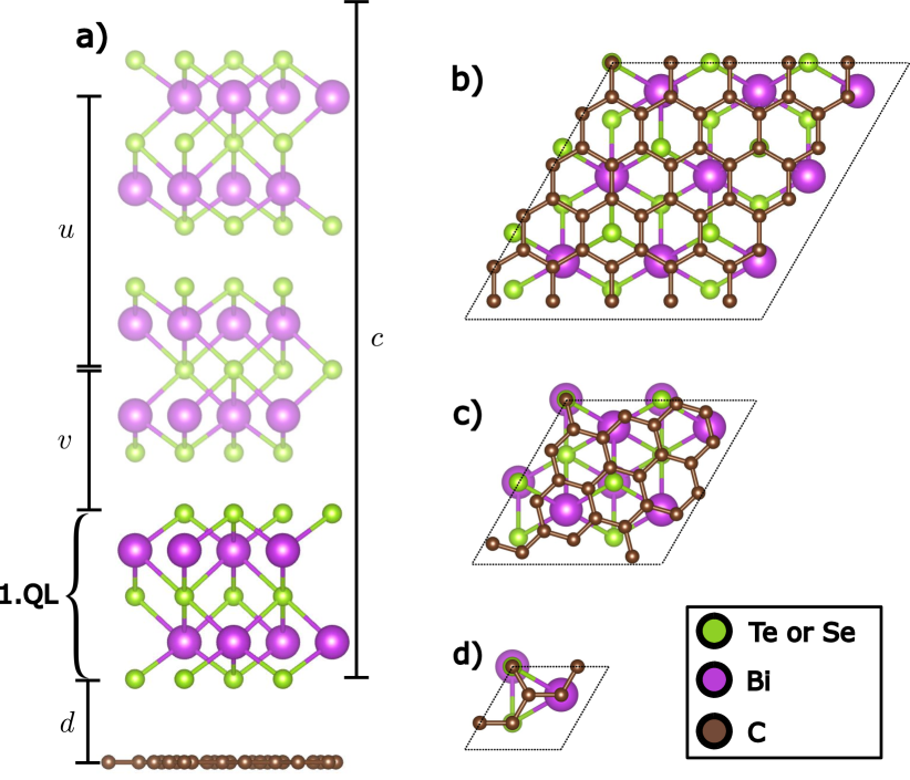
The hexagonal unit cell of the TIs is described by the two lattice parameters and as well as the atomic constants and (all geometry parameters for Bi2Se3 and Bi2Te3 are listed in Tab. 1). While such a unit cell contains 3 quintuple layers (QLs), we use, unless specified otherwise, only one QL to reduce computational effort. Due to the short range of proximity effects, the effect of additional QLs on the graphene is almost exclusively via the change of the TI surface state. Since heterostructures with explicitly do not couple to the surface state (see Sec. III), and in accordance with the results of Ref. Zollner and Fabian (2019), we deem the 1QL cases to be representative for . We discuss 3QL cases in App. E and in Subsec. V.2, in connection with .
| [Å] | [Å] | [Å] | [Å] | |
|---|---|---|---|---|
| Graphene | 2.46 | - | - | - |
| Bi2Te3 | 4.386 | 30.497 | 0.4000 | 0.2097 |
| Bi2Se3 | 4.143 | 28.636 | 0.4008 | 0.2117 |
We construct the supercells by implementing the coincidence lattice method (Koda et al., 2016; Carr et al., 2020), which is detailed in Ref. (Naimer et al., 2021). We give integer attributes to a monolayer supercell. The lattice vectors and are defined as a linear combination of the primitive lattice vectors and :
| (1) | ||||
| (2) |
By placing an (,) graphene supercell beneath an (,) TI supercell, we construct the graphene/TI heterostructure supercell, which then has a certain relative twist angle depending on , , and .
If not specified otherwise, our supercells follow the convention of a ’Top’ configuration. This means that at a corner of the supercell a carbon atom resides directly beneath a Te or Se atom, see Fig. 1. Considering different configurations (see App. D) we find that for large enough supercells the proximity SOC is rather insensitive to the changes of the atomic registry, similar to what is observed in graphene/TMDC heterostructures (Naimer et al., 2021; Gmitra et al., 2016).
In order to obtain commensurate supercells for periodic DFT calculations, one of the layers (or both) need to be strained. We thus introduce the strain factor , which depends on the lattice constant of the TI and is therefore different for Bi2Se3 and Bi2Te3. Since the low energy Dirac spectrum of graphene is (apart from the renormalization of the Fermi velocity) rather robust against biaxial strain smaller than 20% (Si et al., 2016; Choi et al., 2010), we choose to leave the TI unstrained and strain graphene.
| [%] | [%] | (1QL) | (3QL) | |||
|---|---|---|---|---|---|---|
| 0.0 | ( 0 2 ) | ( 0 1 ) | -10.85 | -15.79 | 13 | 23 |
| 0.0 | ( 0 5 ) | ( 0 3 ) | 6.98 | 1.05 | 95 | 185 |
| 4.3 | ( 2 3 ) | ( 1 2 ) | 8.22 | 2.22 | 73 | 143 |
| 4.7 | ( 4 3 ) | ( 2 2 ) | 1.54 | -4.09 | 134 | 254 |
| 8.9 | ( 1 5 ) | ( 0 3 ) | -3.93 | -9.26 | 107 | 197 |
| 10.9 | ( 2 1 ) | ( 1 1 ) | 16.72 | 10.25 | 29 | 95 |
| 13.9 | ( 1 3 ) | ( 0 2 ) | -1.1 | -6.58 | 46 | 86 |
| 16.1 | ( 3 1 ) | ( 1 1 ) | -14.35 | -19.1 | 41 | 71 |
| 17.5 | ( 3 2 ) | ( 1 2 ) | 8.22 | 2.22 | 73 | 143 |
| 19.1 | ( 4 0 ) | ( 2 1 ) | 17.93 | 11.4 | 67 | 137 |
| 19.1 | ( 5 0 ) | ( 2 1 ) | -5.66 | -10.88 | 85 | 155 |
| 19.1 | ( 2 4 ) | ( 0 3 ) | 1.08 | -4.52 | 101 | 191 |
| 20.8 | ( 4 3 ) | ( 1 3 ) | 5.68 | -0.17 | 139 | 269 |
| 21.1 | ( 5 1 ) | ( 2 2 ) | 10.93 | 4.78 | 122 | 242 |
| 21.8 | ( 4 2 ) | ( 1 2 ) | -10.85 | -15.79 | 91 | 161 |
| 30.0 | ( 1 1 ) | ( 0 1 ) | 2.94 | -2.77 | 11 | 21 |
| 30.0 | ( 7 0 ) | ( 2 2 ) | -11.77 | -16.66 | 158 | 278 |
Also, to focus on twist-angle effects, the used interlayer distance Å separating the monolayers (see Fig. 1) is the same for all studied supercells. We do not perform structural relaxation calculations for our systems assuming that – as discussed in (Naimer et al., 2021) for TMDCs – this will only lead to a modification of the staggered potential (due to rippling effects) and leave the SOC parameters largely unaffected. To avoid interactions between periodic images in our slab geometry, we add a vacuum of 20 Å. All graphene/TI heterostructures are set up using the atomic simulation environment (ASE) (Bahn and Jacobsen, 2002) code. The structural parameters of the heterostructures are collected in Tab. 2 and some representative examples are visualized in Fig. 1.
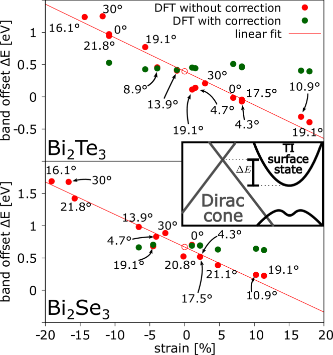
In Ref. (Naimer et al., 2021) we investigated graphene/TMDC heterostructures and reported a linear connection between the strain (enforced on the graphene) and the band offset between the graphene and the transition-metal dichalcogenide (TMDC) band structure. For the graphene/TI heterostructures we also observe a linear relation, see Fig. 2, allowing us to estimate the apparent zero-strain band offset for both cases: meV for Bi2Te3 and meV for Bi2Se3. We then apply a transverse electric field to each supercell to reduce the band offset to the zero-strain one.
As a reference point for the TI energies we use the TI surface state (or for the 1QL case: the remnants of the surface state) at . Unlike thin TMDC monolayers, the TI multilayers we use are rather thick, having a thickness of 7 Å per QL. This makes them more vulnerable for unwanted side effects of the electric field to the band structure. A prominent example is the splitting of the TI surface state (Zollner and Fabian, 2021) into a state living at the lower TI surface (close to the graphene monolayer) and one living at the upper TI surface (further away from the graphene monolayer). However, we expect the consequences for the proximity SOC to be rather minimal, since the proximity SOC is induced mainly by the atomic orbitals close to the graphene monolayer in real space.
The computational methodology for obtaining DFT electronic band structures of the graphene/TI supercells is detailed in App. A.
III Qualitative picture of Interlayer interaction in k space
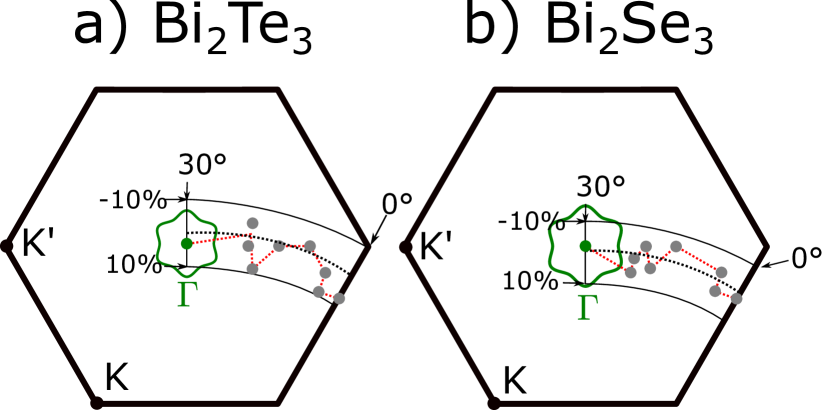
Ref. (Koshino, 2015) details by generalized Umklapp processes how in twisted heterostructures only certain -points of the two layers can interact with each other. In the graphene/TI heterostructures our focus is on the graphene low energy Dirac states. Therefore we are interested in the -points in the 2D primitive TI (Bi2Se3 or Bi2Te3) unit cell, with which the Dirac cone of graphene will primarily interact (and obtain its SOC from) in a graphene/TI heterostructure. The principle contribution comes from three -points, which are equivalent due to symmetry. The location of these -points depends both on the twist angle between the two materials and the ratio of their lattice constants, so in this case . Since the strain we apply to the graphene in order to construct a commensurate heterostructure changes , we can identify strain and twist angle as the two relevant factors for our calculations. Fig. 3 shows for both Bi2Se3 and Bi2Te3, where those -points lie for the supercells listed in Tab. 2.
As is also clear from Fig. 3, for the supercell the graphene Dirac cone interacts exactly with the -point of the TI. Since this is the reciprocal lattice momentum at which the surface states of the TI reside, this particular twist angle is expected to be special. Indeed, Ref. (Song et al., 2018) reports SOC of the Kane-Mele type appearing in DFT calculations on a graphene/Bi2Se3 heterostructure with a 30° twist angle. We dedicate Subsec. V.2 to discussing this special case.
IV Effective Hamiltonian
In order to find the twist-angle dependence of the proximity induced SOC in graphene’s Dirac bands due to the coupling with the TIs, we fit the DFT band structures at the Dirac points to a model Hamiltonian (Gmitra and Fabian, 2015). The Hamiltonian comprises the orbital part and the spin-orbit part . The latter is composed of the intrinsic spin-orbit coupling and the Rashba coupling :
| (3) |
The orbital part describes the dispersion of the graphene Dirac cone linearized around the /-point; accordingly, is the electron wave vector measured from /. It also includes a staggered potential , caused by the substrate’s asymmetrical influence on the graphene A- and B-sublattice:
| (4) |
Here, is the Fermi velocity of the Dirac electrons and are the Pauli matrices operating on the sublattice (A/B) space. The parameter for and for .
The intrinsic spin-orbit Hamiltonian
| (5) |
and the Rashba spin-orbit Hamiltonian
| (6) |
both additionally act on the spin space, which is described by the spin Pauli matrices and ; and are the valley-Zeeman (Gmitra and Fabian, 2015; Wang et al., 2015) SOC (sublattice-odd) and the Kane-Mele (Kane and Mele, 2005a) SOC (sublattice-even) respectively. The Rashba SOC term is defined by a magnitude and a phase angle . The latter is present in symmetric structures (Li and Koshino, 2019; David et al., 2019; Naimer et al., 2021) and rotates the spin texture about the -axis, adding a radial component to the Rashba field.
We choose to limit the Rashba parameter to positive values . A sign change of then corresponds to an additional phase shift of by a half rotation, i.e. . To make this clear we always write .
We only construct heterostructure with angles between 0° and 30°. The parameters for all other twist angles can be obtained by the following symmetry rules:
Twisting clockwise or counterclockwise from 0° influences only the Rashba phase angle:
| (7) | ||||
| (8) | ||||
| (9) | ||||
| (10) |
Additionally a twist by 60° corresponds to switching the sublattices of graphene and therefore changes the sign of the sublattice-sensitive parameters:
| (11) | ||||
| (12) | ||||
| (13) | ||||
| (14) |
V Results
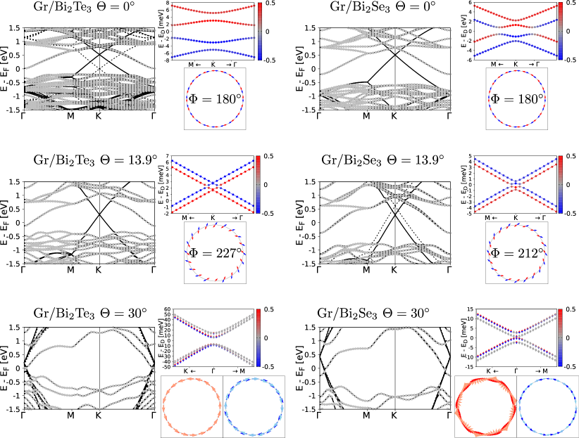
We calculate the electronic band structures for all supercells listed in boldface in Tab. 2 by means of DFT for the 1QL case. Fig. 4 shows a few representative band structures. In addition it shows zooms to the graphene Dirac cone and the in-plane spin structure around it. It is clearly visible that the proximity SOC and therefore the structure of the Dirac cone is different for different angles. Fitting the Dirac cones to the model Hamiltonian, Eq. (3), results in effective model parameters (see Tab. 3) which can be used to compare different twist angles. In the following, we discuss these results separately for twist angles below 20 and for the twist angle at 30, as the two cases have distinct features.
V.1 Results I:
For twist angles the graphene Dirac point acquires its SOC mainly from parts of the TI first BZ which are away from the -point. The corresponding Bloch states are not what would form TI surface states, as those appear at . Hence, the overall SOC is weaker than for the case (see next subsection). Additionally, the SOC has similar functional form to that in graphene/TMDC heterostructures (Naimer et al., 2021): both staggered potential and are negligibly small, while and dominate. This is in agreement with earlier calculations (Zollner and Fabian, 2021; Song et al., 2018). Also, the Rashba phase angle vanishes () for due to symmetry.
Fig. 5 depicts the twist-angle dependence of the extracted SOC parameters , , and . The qualitative structure is the same for both materials Bi2Se3 and Bi2Te3. It exhibits a special feature of the graphene/TI heterostructures, namely, the sign change of at about . Since increasing the TI thickness from 1QL to 3QL leaves the sign of unaffected (see App. E), it is reasonable to conjecture, taking into account the short range of the proximity effect in van der Waals heterostructures, that the valley-Zeeman SOC changes sign also for graphene on bulk TI.
Since heterostructures with large strain ( couple to very different parts of the TI Brillouin zone, they deviate strongly from the zero-strain path in Fig. 3 and are therefore depicted as transparent points in Fig. 5. Nevertheless, we can infer from these calculation that there can be a sign change not only by sweeping the twist angle , but also by sweeping the strain . E.g., a graphene/Bi2Te3 heterostructure with a fixed twist angle of 19.1° changes the sign of , when going from moderate strains (=-5.66%, =1.08%) to a very large positive strain (=17.93%). We estimate this sign change to happen at 8% to 10% for twist angles . Although such heterostructures are not directly realizable in an experiment (due to the large strain), it is a relevant side note for heterostructures using similar TIs or alloys of TIs, which have slightly different lattice constants. The sign changes are visualized in the second line of Fig. 5.
Remarkably, there are two irregularities that appear. Firstly, there is a rather abrupt sign change in between the two last data points ( and ) of the Bi2Se3 heterostructures in Fig. 5(b). This could be due to the close vicinity of the Dirac cone of the heterostructure to the TI surface state: Despite the rather small difference in twist angle, due to its different strain its Dirac cone couples to a point closer to the line rather than the line. Since in this direction in space the slope of the TI surface state is less steep, it is closer to the Dirac cone in energy. And apparently this influence manifests in the sign change of . Secondly, The magnitude of the Rashba SOC is generally smaller than the magnitude of . It seems to almost monotonically decrease for . However, when looking again at the Bi2Se3 data point, we see a strong increase of , again likely related to the Dirac cone’s vicinity to the remnants of the surface state.
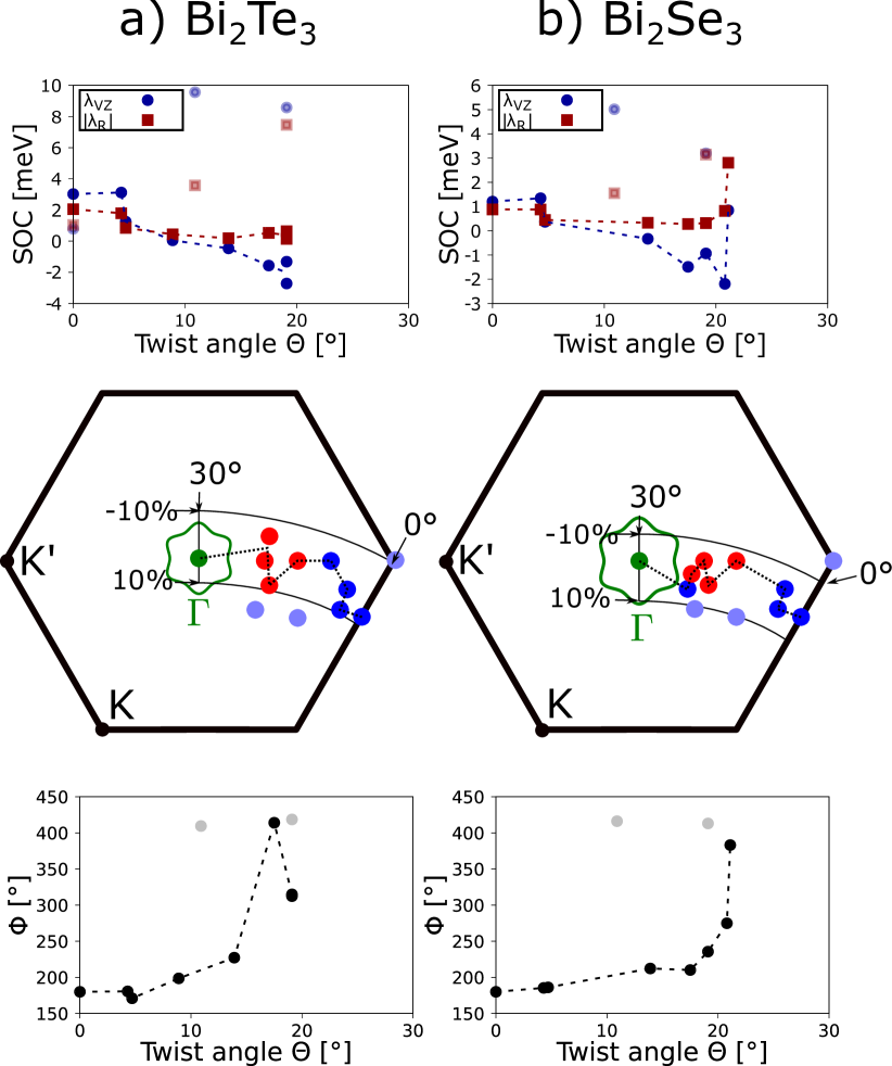
The Rashba phase angle is essential for collinear charge-to-spin conversion (Zhao et al., 2020; Ingla-Aynés et al., 2022; Lee et al., 2022; Péterfalvi et al., 2022; Veneri et al., 2022), since for and collinear charge-to-spin conversion is forbidden. The twist-angle dependence of in graphene-based heterostructures is not well explored apart from the symmetry-dictated fact that and both entail or (Li and Koshino, 2019; Péterfalvi et al., 2022; Naimer et al., 2021).
For intermediate twist angles , there can be either no sign change or a sign change . The latter is especially interesting, since it implies the existence of a twist angle for which or and therefore a purely radial Rashba spin structure and purely collinear charge-to-spin conversion. Ref. (Péterfalvi et al., 2022) predicts such a sign change to happen for certain graphene/TMDC heterostructures based on a tight binding model, although DFT results Naimer et al. (2021); Lee et al. (2022) are at odds with that prediction. Our results seem to strongly indicate that such a sign change could occur for graphene/TI heterostructures with the twist angle corresponding to a purely radial spin structure being (see Fig. 5).
V.2 Results II:
By combining a graphene supercell () and a 1 1 TI supercell () one can create a heterostructure with a twist angle of . Even though other heterostructures with such a twist angle can be constructed (e.g. ), the former is unique in a few ways:
-
1.
It is a notably small supercell. For larger heterostructures the shifting degree of freedom is mostly irrelevant for the proximity SOC, because the graphene will have many different local atomic registries, which will always result in some average proximity effect. Since this is impossible for such a small supercell, the shifting degree of freedom will strongly affect the low energy Dirac cone band structure (see App. D).
-
2.
The - and -points of the primitive graphene first Brillouin zone are folding back to the -point of the supercell’s first Brillouin zone, creating an 8 band Dirac cone.
- 3.
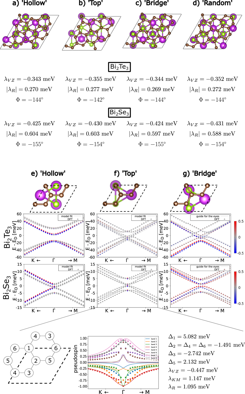
According to the first point, we observe very different low energy spectra for the four different shifting configurations (see Fig. 9). For all but the ‘Hollow’ configuration we see eight distinct bands, degenerate only at the -point, where Cramer’s rule strictly demands it. The ’Hollow’ configuration is the energetically most favourable one and therefore the one we will focus on (all plots in the main manuscript regarding the supercell represent this ’Hollow’ case). It entails band structures consisting of four band pairs with energy splittings within such a band pair being on the eV range. These small splittings lead to a certain spin structure (see App. B), that has also been found and discussed in Ref. (Song et al., 2018). However, since the splitting is very small and the resulting spin structure is very elusive, we only use the simple Hamiltonian (Eq. (3)) described in Sec. IV for the fittings in the main manuscript (we reduce the eight bands to four by ignoring one band of each almost-degenerate band pair). This on the one hand allows for better comparability with the parameters of the other twist angles, but on the other hand fails to describe the spin structure. In App. C we fit the Dirac cones with an alternative fitting Hamiltonian which is akin to the one used in Ref. Song et al. (2018) and find that the fitting parameters are very similar.
Due to the aforementioned backfolding, we cannot include spin-z expectation values in the fitting procedure. However, pseudospin (sublattice imbalance) is used in addition to the energies to unambiguously determine the correct parameters. For the ‘Hollow’ case pseudospin is always zero, therefore demanding (this can alternatively be deduced from symmetry). For the ‘Top’ case the pseudospins of the eight bands form a complicated structure, which can be roughly reproduced using a full tight binding model Hamiltonian including certain onsite potentials (see App. D). The energies and pseudospins of the ‘Bridge’ case could not be sufficiently reproduced by either Hamiltonian.
The in-plane spin structure of the graphene/Bi2Se3 30° case (see Fig. 4, right column, last line) can clearly not be described with the Hamiltonian in Eq. (3). For the graphene/Bi2Te3 30° case (see Fig. 4, left column, last line) the band pairs seem to exhibit a typical tangential Rashba in-plane spin structure. However, the order in which clockwise (c) or counterclockwise (cc) spin structures appear (starting from the energetically lowest band pair) is alternating, i.e. cc-c-cc-c. For the usual Rashba case it is cc-c-c-cc. Therefore, the in-plane spin structures also cannot be described by Eq. (3) and we cannot estimate a Rashba phase angle from such calculations. This means there appears to be physics in the commensurate system, which the simple model Hamiltonian (Eq. (3)) is not able to capture. Assuming that this physics stems from the specific atomic registry dependence, an unstrained incommensurate structure should still be well described by the simple model Hamiltonian (Eq. (3)). Based on the results from last line of plots of Fig. 5, we presume that the phase angle of such an incommensurate structure will be shifted by with respect to the one at . Experimentally, a commensurate structure could be the result of chemical vapor deposition (CVD) or molecular beam epitaxy (MBE) fabrication, while the incommensurate structure might be obtained by a exfoliation method.
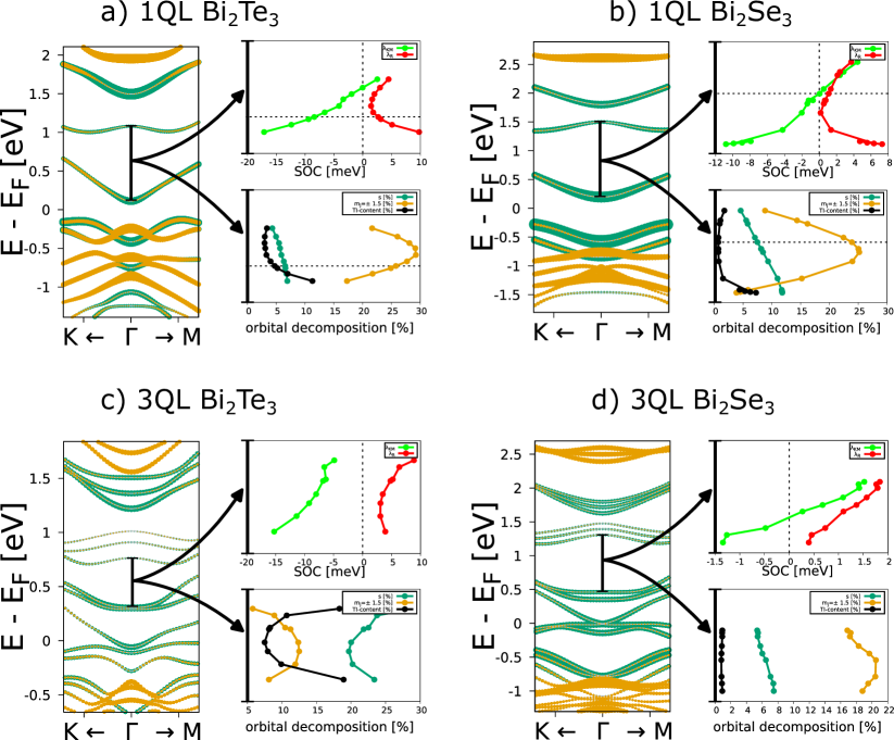
For the Dirac cone lies (locally) within a band gap. As already mentioned for the Dirac cone now lies directly on top of the TI surface state at the -point. Therefore, both the thickness of the TI (determining the concrete form of the surface state) and an applied transversal electric field (determining the relative position of the Dirac cone with respect to the surface state) can be expected to strongly influence the proximity SOC induced in the graphene. In the following, we will focus on the ‘Hollow’ shifting configuration, since it is the energetically most favourable.
In Fig. 6 we show the electric field dependence of the parameters for the 1QL case and the 3QL case. The Dirac cone is shifted through the range marked in black within the TI band structure using an electric field. With as stated before, the two remaining parameters and are both in the meV range. When the Dirac cone comes close to a TI band, the SOC becomes larger with both parameters reaching up to 20 meV in magnitude. Parameter can remarkably change sign whilst the Dirac cone moves from one band to another. Additionally, we depict the orbital decomposition of the Dirac cone. The black curve, showing the general TI-content and therefore the strength of the proximity effect will unsurprisingly increase when nearing one of the TI bands. We find TI p-orbitals to be contributing the most to the proximity effects (), while s-orbitals contribute to a less, but still significant, amount (). The dark green curve shows that this distribution stays roughly constant, when shifting the Dirac cone, with a tendency for higher s-orbital content near the surface state. The d-orbitals contribution is negligibly small. Distinguishing even further, we investigated the percentage of p-orbitals with and those with . This distinction is essentially the equivalent of distinguishing between px/y- and pz-orbitals in a spinless case, only now that SOC is present is not a good quantum number and must be replaced with . We find that the orbitals make up roughly 20% of the contributing p-orbitals, which is rather high, considering the Dirac cone pz orbitals overlap more with other pz orbitals and that the TI bands near the Dirac cone consist of hardly any states with . We conclude that an astonishingly large contribution to the proximity effect is coming from bands more than 2 eV away from the Dirac cone in the valence and conduction band, rather than from the surface state itself. Therefore, when the Dirac cone approaches any nearby band with low content, it will acquire a significant proximity effect from it and the relative contribution of the deep-lying states decreases. This corresponds to a decline of the yellow curve indicating relative p-orbital content.
Another interesting feature of the band structure is the separation into two distinct kinds of band pairs, occurring in an alternating fashion. One of those kind of band pairs inherits its properties (mainly spin structure and orbital composition) from the nearby surface state, while the other one inherits its properties from the deep-lying states. This distinction is described in App. B in detail.
VI Summary
We systematically investigated the proximity induced SOC in twisted graphene/Bi2Se3 and graphene/Bi2Te3 heterostructures. After determining an approximate zero-strain band offset, we correct the band offset of all structures accordingly and fit their energies and spin to an established SOC Hamiltonian to extract relevant SOC parameters. We separately consider supercells in a twist-angle range , which are barely affected by the TI surface state, and one special highly commensurate supercell at , which is heavily influenced by the surface state. For the supercells we extract the twist-angle dependence of the relevant types of SOC, which are valley-Zeeman () and Rashba (, ). Upon twisting, we witness a change of the valley-Zeeman sign at . Additionally we witness a sign change upon changing the strain at about +8% to +10% strain for twist angles . We confirm that the Rashba phase angle has a value of at . For increasing twist angle the phase angle also increases and crosses for , where a purely radial in-plane spin structure occurs. Assuming that this trend continues for twist angles , it seems likely that (for incommensurate heterostructures) the phase angle will have a value of at a twist angle of .
The case of the highly commensurate supercell was investigated more closely. We consider the specific shifting configuration ’Hollow’, since it is energetically the most favourable. Since its symmetries do not allow for valley-Zeeman SOC, the significant SOC types are Rashba () and Kane-Mele (). Due to backfolding effects, the Dirac cone coincides with the TI surface state in space. Using an electric field, we shift the Dirac cone within a local TI band gap, which results in a change of the sign of . Furthermore, orbital decomposition considerations reveal that the Dirac cone consists of two distinct alternating types of bands, one of which obtains its proximity SOC almost exclusively from higher lying bands.
In addition, we show calculations indicating that the effect of lateral shifting is irrelevant for the cases within , while having a strong effect on the highly commensurate supercell.
| E-field | ||||||||||||||
| [%] | [°] | [meV] | [meV] | [meV] | [meV] | [eV] | [] | [°] | [meV] | [meV] | [meV] | [meV] | [eV] | |
| Bi2Te3 | ||||||||||||||
| 0 | -10.85 | 180 | 2.325 | 0.698 | 1.256 | 1.452 | 0.972 | 5.554 | 180 | 2.257 | 0.528 | 0.786 | 1.037 | 0.529 |
| 0 | 6.98 | 180 | 0.002 | -0.004 | 1.934 | 0.748 | -0.015 | -3.399 | 180 | 0.037 | -0.022 | 3.026 | 2.054 | 0.510 |
| 4.3 | 8.22 | 152 | 0.000 | -0.006 | 2.038 | 0.512 | -0.072 | -3.838 | 181 | 0.034 | -0.024 | 3.126 | 1.791 | 0.471 |
| 4.7 | 1.54 | 146 | 0.002 | -0.003 | 1.019 | 0.557 | 0.141 | -2.199 | 171 | -1.936 | -0.002 | 1.254 | 0.852 | 0.444 |
| 8.9 | -3.93 | 199 | 0.418 | -0.002 | -0.319 | 0.342 | 0.458 | 0.247 | 199 | -0.001 | 0.008 | 0.050 | 0.438 | 0.442 |
| 10.9 | 16.72 | 19 | -0.067 | 0.271 | 13.694 | 7.140 | -0.309 | -6.171 | 50 | 0.109 | -0.082 | 9.562 | 3.574 | 0.407 |
| 13.9 | -1.1 | -130 | 0.010 | 0.011 | -0.464 | 0.178 | 0.407 | -0.145 | -133 | 0.010 | 0.006 | -0.467 | 0.183 | 0.418 |
| 17.5 | 8.22 | -10 | 0.001 | 0.154 | 3.513 | 2.897 | -0.044 | -3.624 | 54 | 0.014 | -0.028 | -1.568 | 0.531 | 0.458 |
| 19.1 | 1.08 | -42 | -0.001 | 0.024 | -0.814 | 0.980 | 0.114 | -2.406 | -45 | -0.001 | 0.005 | -1.320 | 0.143 | 0.114 |
| 19.1 | 17.93 | - | - | - | - | - | -0.393 | -5.656 | 59 | -0.034 | -0.035 | 8.578 | 7.467 | 0.396 |
| 19.1 | -5.66 | - | - | - | - | - | 0.772 | 1.797 | -48 | 0.007 | 0.006 | -2.720 | 0.636 | 0.427 |
| 30 | 2.94 | - | 0.000 | -12.400 | 0.000 | 5.089 | 0.255 | -0.771 | - | 0.000 | -8.413 | 0.000 | 2.703 | 0.324 |
| Bi2Se3 | ||||||||||||||
| 0 | -15.79 | 180 | 1.496 | 0.252 | 0.726 | 0.816 | 1.423 | - | - | - | - | - | - | - |
| 0 | 1.05 | 180 | 0.002 | -0.007 | 1.217 | 0.901 | 0.704 | 0.074 | 180 | 0.003 | -0.007 | 1.204 | 0.881 | 0.692 |
| 4.3 | 2.22 | -178 | -0.001 | -0.006 | 1.195 | 0.621 | 0.518 | -1.36 | -175 | 0.004 | -0.010 | 1.344 | 0.879 | 0.695 |
| 4.7 | -4.09 | 190 | 0.001 | -0.005 | 0.381 | 0.616 | 0.831 | 1.05 | -174 | -0.001 | 0.000 | 0.369 | 0.447 | 0.592 |
| 10.9 | 10.25 | 47 | -0.049 | 0.002 | 3.175 | 1.024 | 0.240 | -4.114 | 56 | 0.054 | -0.018 | 5.016 | 1.554 | 0.644 |
| 13.9 | -6.58 | -155 | 0.004 | 0.007 | -0.496 | 0.623 | 0.982 | 2.216 | -148 | 0.003 | 0.004 | -0.331 | 0.330 | 0.664 |
| 17.5 | 2.22 | 17 | 0.080 | 0.027 | -0.552 | 0.076 | 0.519 | -1.354 | -150 | 0.006 | -0.017 | -1.490 | 0.281 | 0.692 |
| 19.1 | 11.4 | 47 | 0.035 | 0.006 | 2.304 | 2.217 | 0.225 | -3.624 | 53 | 0.003 | -0.035 | 3.197 | 3.146 | 0.622 |
| 19.1 | -4.52 | -120 | 0.005 | 0.002 | -0.917 | 0.299 | 0.682 | -0.098 | -124 | 0.000 | 0.000 | -0.935 | 0.315 | 0.706 |
| 20.8 | -0.17 | -41 | 0.001 | -0.007 | -1.258 | 0.468 | 0.524 | -1.313 | -85 | -0.008 | -0.031 | -2.194 | 0.819 | 0.669 |
| 21.1 | 4.78 | 23 | 0.022 | -0.028 | 0.600 | 1.680 | 0.388 | -2.36 | 23 | -0.005 | -0.074 | 0.844 | 2.809 | 0.632 |
| 30 | -2.77 | - | 0.000 | 0.517 | 0.000 | 1.340 | 0.754 | 0.617 | - | 0.000 | 0.049 | 0.000 | 1.091 | 0.700 |
Acknowledgements.
This work was funded by the International Doctorate Program Topological Insulators of the Elite Network of Bavaria, the Deutsche Forschungsgemeinschaft (DFG, German Research Foundation) SFB 1277 (Project-ID 314695032), SPP 2244 (project no. 443416183), and by the European Union Horizon 2020 Research and Innovation Program under contract number 881603 (Graphene Flagship), and Flagera project 2DSOTECH.Appendix A Computational Details
All electronic structure calculations are performed implementing density functional theory (DFT) (Hohenberg and Kohn, 1964) using Quantum ESPRESSO (Giannozzi and et al., 2009). Self-consistent calculations are carried out with a point sampling of . The number is listed in Table 4 for all cases. We use charge density cutoffs Ry and wave function kinetic cutoff Ry (Ry for Bi2Se3) for the fully relativistic pseudopotential with the projector augmented wave method (Kresse and Joubert, 1999) with the Perdew-Burke-Ernzerhof exchange correlation functional (Perdew et al., 1996). Graphene’s -orbitals are not included in the calculations. We used Grimme D-2 Van der Waals corrections (Grimme, 2006; Grimme et al., 2010; Barone et al., 2009).
The electric fields are implemented in the DFT calculations using a sawtooth potential in -direction within the quasi 2D unit cell. The electric potential increases linearly in the area of the heterostructure and then falls rapidly in the vacuum.
| (1QL) | (3QL) | |||
|---|---|---|---|---|
| 0.0° | ( 0 2 ) | ( 0 1 ) | 15 | - |
| 0.0° | ( 0 5 ) | ( 0 3 ) | 6 | - |
| 4.3° | ( 2 3 ) | ( 1 2 ) | 9 | 3 |
| 4.7° | ( 4 3 ) | ( 2 2 ) | 3 | - |
| 8.9 ° | ( 1 5 ) | ( 0 3 ) | 3 | - |
| 10.9° | ( 2 1 ) | ( 1 1 ) | 15 | 9 |
| 13.9° | ( 1 3 ) | ( 0 2 ) | 15 | 9 |
| 16.1° | ( 3 1 ) | ( 1 1 ) | 15 | - |
| 17.5° | ( 3 2 ) | ( 1 2 ) | 9 | 3 |
| 19.1° | ( 4 0 ) | ( 2 1 ) | 12 | - |
| 19.1° | ( 5 0 ) | ( 2 1 ) | 6 | - |
| 19.1° | ( 2 4 ) | ( 0 3 ) | 3 | - |
| 19.1° | ( 2 4 ) | ( 0 3 ) | 3 | - |
| 20.8° | ( 4 3 ) | ( 1 3 ) | 3 | - |
| 21.1° | ( 5 1 ) | ( 2 2 ) | 3 | - |
| 21.8° | ( 4 2 ) | ( 1 2 ) | 6 | - |
| 30.0° | ( 1 1 ) | ( 0 1 ) | 45 | 45 |
| 30.0° | ( 7 0 ) | ( 2 2 ) | 3 | - |
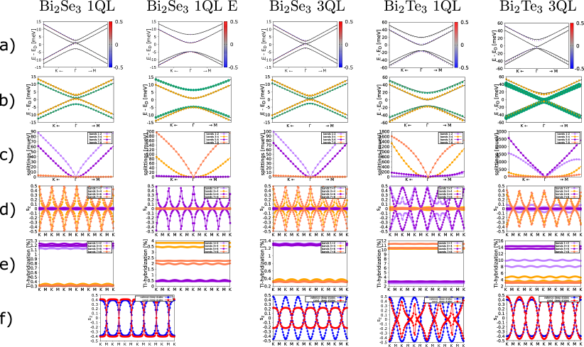
Appendix B Distinguishing the two types of band pairs for
In the main manuscript we touched on the two different kind of band pairs of the Dirac cones in the case of the supercell band structures. We now explore this in detail. In the following we will call band pairs ’type one’, if they have similar properties as the energetically lowest pair of bands in the Bi2Se3 1QL case without electric field (Fig. 7,first column). Accordingly, ’type two’ band pairs then are similar to the band pair energetically above this ’type one’ case. Fig. 7 summarizes the relevant differences of the two types. From Fig. 7 a) and d) we see that the spin-z expectation values of ’type one’ bands are (almost) zero: both bands are unpolarized in the z-direction. In contrast, ’type two’ band pairs show an anisotropic spin structure, where the bands show opposite spin-z values along the - line and vanishing values along the - line. Additionally, the in-plane spin structures we see in Fig. 4 are also bound to the type of band pair. Fig. 7 b) shows that ’type one’ band pairs have relevant contributions from TI states, while ’type two’ band pairs have relevant contributions from TI s-orbital contributions. In Fig. 7 c), we show the splittings within the band pairs: Although both ’type one’ and ’type two’ bands are only split on the eV scale, the splittings of ’type one’ bands are significantly higher and increase to the meV range, when moving away from the center of the Dirac cone at . This splitting is enough to overcome the small spin splitting, seen in ’type two’ bands. In Fig. 7 e), one can see that the TI content of ’type one’ band pairs is higher than that of ’type two’ band pairs by a factor of about 5 on average. Finally, in Fig. 7 f) we see that the same spin structure seen in ’type two’ bands can be seen in deep lying (so energetically low valence or energetically high conduction) bands of the TI. We conclude that on the one hand ’type one’ bands acquire their proximity SOC almost exclusively from deep lying TI states imprinting their spin-z structure and their character. ’type two’ band pairs on the hand acquire the majority of their proximity SOC from the near surface state, which results in a larger splitting destroying the spin-z structure and a significant TI s-orbital content. Comparing the different cases, we see that different structures can entail a different ordering of ’type one’ and ’type two’ bands. Shifting the Dirac cone within the TI band structure can result in a switch of this ordering as well. In fact, we observe such a switching of the ordering by electric field for all of the cases in Fig. 6, except 3QL of Bi2Se3.
Appendix C Alternative fitting Hamiltonian for
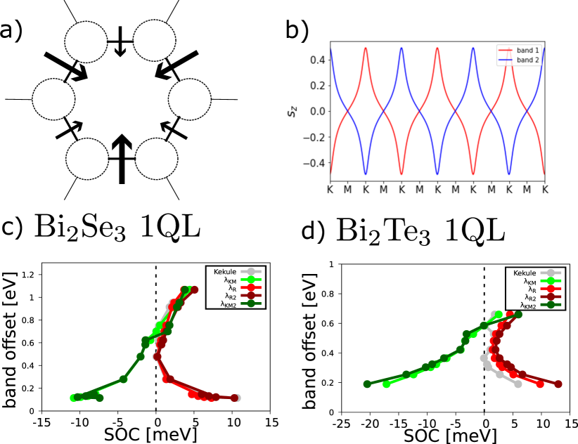
The Dirac cone of the ’Hollow’ supercell has an intricate spin structure (see Fig. 7). In the main manuscript we neglect this fine structure, since it is based on eV splittings within the band pairs. Now, we try to describe this fine structure using a full tight binding Hamiltonian akin to the one used in Ref. (Song et al., 2018):
| (15) |
The single brackets constitute sums over nearest neighbours and the double brackets constitute sums over next nearest neighbours. and are the creation and annihilation operators of an electron at site with spin , is a unit vector pointing from site j to nearest neighbour site i, is a vector containing the Pauli matrices, is equal to +1 for clockwise and equal to -1 for counterclockwise hoppings from site j to i, is +1 for sublattice A and -1 for sublattice B, is the unit vector in -direction and is an in-plane vector representing the electric fields in Fig. 8 a). The first term of describes the orbital part with as (stronger) hopping within the carbon ring depicted in Fig. 8 a) and as the (weaker) hopping parameter between such carbon rings. This makes the Kekule distortion parameter. The second term describes a series of onsite potentials , which are only used in the fitting of the ’Top’ case. The third term describes Kane-Mele and valley-Zeeman SOC. Note that this term is an exact translation of the Kane-Mele and valley-Zeeman terms in Eq. (5) in contrast to Ref. (Song et al., 2018), where the Kane-Mele hoppings only exist on the central carbon ring. The fourth term describes a Rashba SOC related to an electric field in -direction (again an exact translation of the term in Eq. (6)) and an additional Rashba term related to electric fields depicted as arrows in Fig. 8 a). The electric fields are all pointing inward to the carbon ring located under the Se (or Te) atom closest to graphene. There are two distinct types of arrows: to one we assign (large arrows in Fig. 8 a)), to the other (small arrows in Fig. 8 a)). Note that Ref. (Song et al., 2018) do not allow for the in-plane Rashba connected to the smaller arrows.
For the ’Hollow’ case as in the manuscript we have . We obtain good fits only for very small, but non-zero values for and therefore simply fix it to meV for all fits. The remaining parameters therefore are: , and . The general spin-z structure of the ’type two’ band pairs can be modeled with the fittings (see Fig. 8 b)). To model the spin-z structure of a ’type one’ band pair, one can simply set the magnitude of all in-plane electric fields to equal values for the directions indicated by both the large and the small arrows. This will not significantly change the values of the other fitting parameters. Note that the in-plane spin structure also cannot be sufficiently reproduced using this Hamiltonian.
We show the fittings results in Fig. 8 c) and d) for Bi2Se3 and Bi2Te3 respectively for the same electric fields as in Fig 6. We see the same results for Kane-Mele SOC (compare light green to dark green curve). Also the new in-plane Rashba SOC replaces the out-of-plane Rashba SOC (compare red to dark-red curve). The Kekule distortion parameter will follow a similar behaviour as the Rashba SOC increasing drastically in the vicinity of a TI band.
Appendix D Effect of lateral shifting
For incommensurate heterostructures the lateral shifting degree of freedom does not play a role. Assuming a sample infinite in - and -direction, every shifting configuration exists somewhere on the sample. The physical properties of the configurations will then average out, when considering the properties of the whole material. However, the structures used in our DFT calculations are commensurate to be computationally viable and the lattice constants are forced by strain to be compatible. Therefore, different lateral relative shifts might ensue different physical properties including different proximity induced SOC.
Naturally, this effect is less relevant for large supercells, for which an averaging over the different shifts will occur within the supercell. We show this by investigating the shifting-dependence for two supercells: the 13.9° and the 30° supercell. While the former consists of a total of 46 atoms and gives enough area for the different configurations to average out, the latter only consists of 13 atoms. Therefore, different lateral shifting positions will lead to different effects on the Dirac cone for the 30° supercell.
We defined 4 different shifting options, ’Hollow’, ’Top’, ’Bridge’ and ’Random’, which we show in Fig. 9. The keywords indicate how the Te atom closest to the graphene layer is positioned with respect to the graphene structure. For the 30° case there is only one such atom per unit cell, while for the 13.9° supercell there are multiple ones, with different positions (we describe the one closest to the corner of the supercell). Therefore, in the 13.9° case, the Dirac cones for the different shifting positions look almost the same, as the extracted fitting parameters show hardly any difference. In contrast, the Dirac cone of the 30° case varies widely depending on the lateral shift.
We now focus on the 30° supercell. Since the ’Hollow’ configuration is the energetically most favorable and has the simplest band structure, we focus on it in the main manuscript. Additionally, we fitted the Dirac cone of the ’Top’ case to a full tight binding Hamiltonian, since the simple model Hamiltonian (Eq. (3)) in the main manuscript is not able to capture the features of the band structure, which come from the specific shifting position with respect to the graphene supercell. By using the same SOC parameters , and and additionally extending the sublattice imbalance to a general onsite potential (see Eq. (15)) for the six carbon atoms, we were able to describe the Dirac cone of the ’Top’ configuration reasonably well (see Fig. 9). For all eight bands, the spin-z expectation values are zero, while the pseudospin shows an intricate structure. For the ’Bridge’ case, we were not able to find satisfying fitting parameters.
Appendix E Effect of increased thickness of the TI slab
Varying the thickness of the TI layer changes its band structure. When increasing the number of Quintuple layers (QLs), one can see the TI surface state at fully forming. While for 1 QL the overlap between the upper and lower surface states opens a large gap, the surface states of the 3QL case are spatially separated enough for the characteristic linear sloped surface state to arise. Since the graphene Dirac cone of the supercell interacts directly with the TI surface state, it will be affected significantly by the exact form of the surface state and therefore by the thickness of the TI.
But also, for the other twist angles, a dependency on the TI thickness is not excluded, since also the TI bands away from are influenced by this change which can in turn then change the proximity SOC. To investigate this, we calculated the band structures for the 3QL cases of some of our supercells and gather the extracted parameters in Tab. 5. Note, that we compare the results without electric field corrected band offsets, because the 3QL TI band structure is significantly more susceptible to unwanted distortion by the electric field. However, since we are only comparing the 1QL case with the 3QL case, which both have the same strain, using the parameters from the uncorrected calculations is a valid approach. The table shows, that while in most of the scenarios the SOC is not strongly affected by the TI thickness, there are two cases highlighting the importance of the TI thickness:
-
1.
For the Gr/Bi2Te3 supercell, the change from 1QL to 3QL changes the Rashba phase angle by a significant amount from to only .
-
2.
For the Gr/Bi2Se3 supercell, the 1QL case is dominated by valley-Zeeman type SOC , while in the 3QL case the Rashba type SOC is dominating. Here, the vicinity to the TI surface state in space might already be a reason for this massive change in proximity SOC.
In conclusion, we see that for the proximity SOC dependency on the TI thickness is overall not to large, but should not fully be neglected.
| thickness | [°] | [meV] | [meV] | [meV] | [°] |
| Bi2Te3 | |||||
| 1QL | 4.3 | -0.01 | 2.04 | 0.52 | 152 |
| 3QL | 4.3 | 0.01 | 1.65 | 0.50 | 79 |
| 1QL | 13.9 | 0.01 | -0.46 | 0.18 | -130 |
| 3QL | 13.9 | 0.01 | -0.36 | 0.28 | -142 |
| 1QL | 17.5 | 0.16 | 3.51 | 2.90 | -10 |
| 3QL | 17.5 | 0.08 | 3.35 | 2.06 | -25 |
| Bi2Se3 | |||||
| 1QL | 4.3 | -0.01 | 1.19 | 0.62 | -178 |
| 3QL | 4.3 | 0.00 | 1.10 | 0.38 | 171 |
| 1QL | 10.9 | 0.01 | 3.18 | 1.02 | 47 |
| 3QL | 10.9 | 0.01 | 3.24 | 1.00 | 46 |
| 1QL | 13.9 | 0.01 | -0.50 | 0.62 | -155 |
| 3QL | 13.9 | 0.00 | -0.43 | 0.60 | -154 |
| 1QL | 17.5 | 0.03 | -0.55 | 0.08 | 17 |
| 3QL | 17.5 | -0.00 | 0.02 | 0.32 | 23 |
References
- Singh et al. (2016) Simranjeet Singh, Jyoti Katoch, Jinsong Xu, Cheng Tan, Tiancong Zhu, Walid Amamou, James Hone, and Roland Kawakami, “Nanosecond spin relaxation times in single layer graphene spin valves with hexagonal boron nitride tunnel barriers,” Appl. Phys. Lett. 109, 122411 (2016).
- Drögeler et al. (2016) Marc Drögeler, Christopher Franzen, Frank Volmer, Tobias Pohlmann, Luca Banszerus, Maik Wolter, Kenji Watanabe, Takashi Taniguchi, Christoph Stampfer, and Bernd Beschoten, “Spin Lifetimes Exceeding 12 ns in Graphene Nonlocal Spin Valve Devices,” Nano Lett. 16, 3533 (2016).
- Bolotin et al. (2008) K.I. Bolotin, K.J. Sikes, Z. Jiang, M. Klima, G. Fudenberg, J. Hone, P. Kim, and H.L. Stormer, “Ultrahigh electron mobility in suspended graphene,” Solid State Communications 146, 351–355 (2008).
- Du et al. (2008) Xu Du, Ivan Skachko, Anthony Barker, and Eva Y. Andrei, “Approaching ballistic transport in suspended graphene,” Nature Nanotechnology 3, 491–495 (2008).
- Kane and Mele (2005a) C. L. Kane and E. J. Mele, “Quantum Spin hall effect in graphene,” Phys. Rev. Lett. 95, 226801 (2005a).
- Kane and Mele (2005b) C. L. Kane and E. J. Mele, “Z2 topological order and the quantum spin hall effect,” Phys. Rev. Lett. 95, 146802 (2005b).
- Qiao et al. (2010) Zhenhua Qiao, Shengyuan A Yang, Wanxiang Feng, Wang-Kong Tse, Jun Ding, Yugui Yao, Jian Wang, and Qian Niu, “Quantum Anomalous Hall Effect in Graphene from Rashba and Exchange Effects,” Phys. Rev. B 82, 161414(R) (2010).
- Ren et al. (2016) Yafei Ren, Zhenhua Qiao, and Qian Niu, “Topological phases in two-dimensional materials: a review,” Rep. Prog. Phys. 79, 066501 (2016).
- Frank et al. (2018) Tobias Frank, Petra Högl, Martin Gmitra, Denis Kochan, and Jaroslav Fabian, “Protected pseudohelical edge states in -trivial proximitized graphene,” Phys. Rev. Lett. 120, 156402 (2018).
- Högl et al. (2020) Petra Högl, Tobias Frank, Klaus Zollner, Denis Kochan, Martin Gmitra, and Jaroslav Fabian, “Quantum anomalous hall effects in graphene from proximity-induced uniform and staggered spin-orbit and exchange coupling,” Phys. Rev. Lett. 124, 136403 (2020).
- Khoo et al. (2017) Jun Yong Khoo, Alberto F. Morpurgo, and Leonid Levitov, “On-Demand Spin-Orbit Interaction from Which-Layer Tunability in Bilayer Graphene,” Nano Lett. 17, 7003 (2017).
- Gmitra and Fabian (2017) Martin Gmitra and Jaroslav Fabian, “Proximity effects in bilayer graphene on monolayer wse2: Field-effect spin valley locking, spin-orbit valve, and spin transistor,” Phys. Rev. Lett. 119, 146401 (2017).
- Island et al. (2019) J. O. Island, X. Cui, C. Lewandowski, J. Y. Khoo, E. M. Spanton, H. Zhou, D. Rhodes, J. C. Hone, T. Taniguchi, K. Watanabe, L. S. Levitov, M. P. Zaletel, and A. F. Young, “Spin–orbit-driven band inversion in bilayer graphene by the van der Waals proximity effect,” Nature 571, 85 (2019).
- Tiwari et al. (2021) Priya Tiwari, Saurabh Kumar Srivastav, and Aveek Bid, “Electric-field-tunable valley zeeman effect in bilayer graphene heterostructures: Realization of the spin-orbit valve effect,” Phys. Rev. Lett. 126, 096801 (2021).
- Amann et al. (2021) Julia Amann, Tobias Völkl, Denis Kochan, Kenji Watanabe, Takashi Taniguchi, Jaroslav Fabian, Dieter Weiss, and Jonathan Eroms, “Gate-tunable spin-orbit-coupling in bilayer graphene-wse2-heterostructures,” arXiv:2012.05718 (2021).
- Zihlmann et al. (2018) Simon Zihlmann, Aron W. Cummings, Jose H. Garcia, Máté Kedves, Kenji Watanabe, Takashi Taniguchi, Christian Schönenberger, and Péter Makk, “Large spin relaxation anisotropy and valley-zeeman spin-orbit coupling in /graphene/-bn heterostructures,” Phys. Rev. B 97, 075434 (2018).
- Cummings et al. (2017) Aron W. Cummings, Jose H. Garcia, Jaroslav Fabian, and Stephan Roche, “Giant spin lifetime anisotropy in graphene induced by proximity effects,” Phys. Rev. Lett. 119, 206601 (2017).
- Ghiasi et al. (2017) Talieh S. Ghiasi, Josep Ingla-Aynés, Alexey A. Kaverzin, and Bart J. Van Wees, “Large Proximity-Induced Spin Lifetime Anisotropy in Transition-Metal Dichalcogenide/Graphene Heterostructures,” Nano Lett. 17, 7528 (2017).
- Zhao et al. (2020) Bing Zhao, Bogdan Karpiak, Dmitrii Khokhriakov, Annika Johansson, Anamul Md. Hoque, Xiaoguang Xu, Yong Jiang, Ingrid Mertig, and Saroj P. Dash, “Unconventional charge–spin conversion in weyl-semimetal wte2,” Advanced Materials 32, 2000818 (2020).
- Ingla-Aynés et al. (2022) Josep Ingla-Aynés, Inge Groen, Franz Herling, Nerea Ontoso, C K Safeer, Fernando de Juan, Luis E Hueso, Marco Gobbi, and Fèlix Casanova, “Omnidirectional spin-to-charge conversion in graphene/NbSe2 van der waals heterostructures,” 2D Materials 9, 045001 (2022).
- Péterfalvi et al. (2022) Csaba G. Péterfalvi, Alessandro David, Péter Rakyta, Guido Burkard, and Andor Kormányos, “Quantum interference tuning of spin-orbit coupling in twisted van der waals trilayers,” Phys. Rev. Research 4, L022049 (2022).
- Veneri et al. (2022) Alessandro Veneri, David T. S. Perkins, Csaba G. Péterfalvi, and Aires Ferreira, “Twist angle controlled collinear edelstein effect in van der waals heterostructures,” Phys. Rev. B 106, L081406 (2022).
- Lee et al. (2022) Seungjun Lee, D. J. P. de Sousa, Young-Kyun Kwon, Fernando de Juan, Zhendong Chi, Fèlix Casanova, and Tony Low, “Charge-to-spin conversion in twisted heterostructures,” Phys. Rev. B 106, 165420 (2022).
- Geim and Grigorieva (2013) A. K. Geim and I. V. Grigorieva, “Van der Waals heterostructures,” Nature 499, 419 (2013).
- Duong et al. (2017) Dinh Loc Duong, Seok Joon Yun, and Young Hee Lee, “Van der Waals Layered Materials: Opportunities and Challenges,” ACS Nano 11, 11803 (2017).
- Gmitra and Fabian (2015) Martin Gmitra and Jaroslav Fabian, “Graphene on transition-metal dichalcogenides: A platform for proximity spin-orbit physics and optospintronics,” Phys. Rev. B 92, 155403 (2015).
- Gmitra et al. (2016) Martin Gmitra, Denis Kochan, Petra Högl, and Jaroslav Fabian, “Trivial and inverted dirac bands and the emergence of quantum spin hall states in graphene on transition-metal dichalcogenides,” Phys. Rev. B 93, 155104 (2016).
- Frank et al. (2017) Tobias Frank, Susanne Irmer, Martin Gmitra, Denis Kochan, and Jaroslav Fabian, “Copper adatoms on graphene: Theory of orbital and spin-orbital effects,” Phys. Rev. B 95, 035402 (2017).
- Wang et al. (2015) Zhe Wang, Dong-Keun Ki, Hua Chen, Helmuth Berger, Allan H MacDonald, and Alberto F Morpurgo, “Strong interface-induced spin-orbit interaction in graphene on WS2,” Nat. Commun. 6, 8339 (2015).
- Avsar et al. (2014) A Avsar, J Y Tan, T Taychatanapat, J Balakrishnan, G. K. W. Koon, Y Yeo, J Lahiri, A Carvalho, A S Rodin, E. C. T. O’Farrell, G Eda, A H Castro Neto, and B. Özyilmaz, “Spin–orbit proximity effect in graphene,” Nat. Commun. 5, 4875 (2014).
- Song et al. (2018) Kenan Song, David Soriano, Aron W. Cummings, Roberto Robles, Pablo Ordejón, and Stephan Roche, “Spin Proximity Effects in Graphene/Topological Insulator Heterostructures,” Nano Lett. 18, 2033 (2018).
- Zollner and Fabian (2019) Klaus Zollner and Jaroslav Fabian, “Single and bilayer graphene on the topological insulator : Electronic and spin-orbit properties from first principles,” Phys. Rev. B 100, 165141 (2019).
- Jafarpisheh et al. (2018) S. Jafarpisheh, A. W. Cummings, K. Watanabe, T. Taniguchi, B. Beschoten, and C. Stampfer, “Proximity-induced spin-orbit coupling in graphene/ bi1.5sb0.5te1.7se1.3 heterostructures,” Phys. Rev. B 98, 241402 (2018).
- Khokhriakov et al. (2018) Dmitrii Khokhriakov, Aron W. Cummings, Kenan Song, Marc Vila, Bogdan Karpiak, André Dankert, Stephan Roche, and Saroj P. Dash, “Tailoring emergent spin phenomena in Dirac material heterostructures,” Sci. Adv. 4, eaat9349 (2018).
- Steinberg et al. (2015) H. Steinberg, L. A. Orona, V. Fatemi, J. D. Sanchez-Yamagishi, K. Watanabe, T. Taniguchi, and P. Jarillo-Herrero, “Tunneling in graphene–topological insulator hybrid devices,” Phys. Rev. B 92, 241409 (2015).
- Zalic et al. (2017) A. Zalic, T. Dvir, and H. Steinberg, “High-density carriers at a strongly coupled interface between graphene and a three-dimensional topological insulator,” Phys. Rev. B 96, 075104 (2017).
- Rajput et al. (2016) Shivani Rajput, Yao-Yi Li, Michael Weinert, and Lian Li, “Indirect interlayer bonding in graphene–topological insulator van der waals heterostructure: Giant spin–orbit splitting of the graphene dirac states,” ACS Nano 10, 8450–8456 (2016), pMID: 27617796, https://doi.org/10.1021/acsnano.6b03387 .
- Dang et al. (2010) Wenhui Dang, Hailin Peng, Hui Li, Pu Wang, and Zhongfan Liu, “Epitaxial heterostructures of ultrathin topological insulator nanoplate and graphene,” Nano Lett. 10, 2870 (2010).
- Lee et al. (2015) Paengro Lee, Kyung-Hwan Jin, Si Jin Sung, Jin Gul Kim, Min-Tae Ryu, Hee-Min Park, Seung-Hoon Jhi, Namdong Kim, Yongsam Kim, Seong Uk Yu, Kwang S. Kim, Do Young Noh, and Jinwook Chung, “Proximity effect induced electronic properties of graphene on bi2te2se,” ACS Nano 9, 10861–10866 (2015), pMID: 26549323, https://doi.org/10.1021/acsnano.5b03821 .
- Kiemle et al. (2022) Jonas Kiemle, Lukas Powalla, Katharina Polyudov, Lovish Gulati, Maanwinder Singh, Alexander W. Holleitner, Marko Burghard, and Christoph Kastl, “Gate-tunable helical currents in commensurate topological insulator/graphene heterostructures,” ACS Nano 16, 12338–12344 (2022), pMID: 35968692, https://doi.org/10.1021/acsnano.2c03370 .
- Song et al. (2010) Can-Li Song, Yi-Lin Wang, Ye-Ping Jiang, Yi Zhang, Cui-Zu Chang, Lili Wang, Ke He, Xi Chen, Jin-Feng Jia, Yayu Wang, Zhong Fang, Xi Dai, Xin-Cheng Xie, Xiao-Liang Qi, Shou-Cheng Zhang, Qi-Kun Xue, and Xucun Ma, “Topological insulator bi2se3 thin films grown on double-layer graphene by molecular beam epitaxy,” Appl. Phys. Lett. 97, 143118 (2010).
- Zhang et al. (2014) Junhua Zhang, C. Triola, and E. Rossi, “Proximity effect in graphene–topological-insulator heterostructures,” Phys. Rev. Lett. 112, 096802 (2014).
- De Beule et al. (2017) C. De Beule, M. Zarenia, and B. Partoens, “Transmission in graphene–topological insulator heterostructures,” Phys. Rev. B 95, 115424 (2017).
- Cao et al. (2016) Wendong Cao, Rui-Xing Zhang, Peizhe Tang, Gang Yang, Jorge Sofo, Wenhui Duan, and Chao-Xing Liu, “Heavy dirac fermions in a graphene/topological insulator hetero-junction,” 2D Materials 3, 034006 (2016).
- Jin and Jhi (2013) Kyung-Hwan Jin and Seung-Hoon Jhi, “Proximity-induced giant spin-orbit interaction in epitaxial graphene on a topological insulator,” Phys. Rev. B 87, 075442 (2013).
- Lin et al. (2017) Zhuonan Lin, Wei Qin, Jiang Zeng, Wei Chen, Ping Cui, Jun-Hyung Cho, Zhenhua Qiao, and Zhenyu Zhang, “Competing gap opening mechanisms of monolayer graphene and graphene nanoribbons on strong topological insulators,” Nano Letters 17, 4013–4018 (2017), pMID: 28534404, https://doi.org/10.1021/acs.nanolett.6b05354 .
- Liu et al. (2013) Wenliang Liu, Xiangyang Peng, Xiaolin Wei, Hong Yang, G. Malcolm Stocks, and Jianxin Zhong, “Surface and substrate induced effects on thin films of the topological insulators bi2se3 and bi2te3,” Phys. Rev. B 87, 205315 (2013).
- Popov et al. (2014) Igor Popov, Mauro Mantega, Awadhesh Narayan, and Stefano Sanvito, “Proximity-induced topological state in graphene,” Phys. Rev. B 90, 035418 (2014).
- Naimer et al. (2021) Thomas Naimer, Klaus Zollner, Martin Gmitra, and Jaroslav Fabian, “Twist-angle dependent proximity induced spin-orbit coupling in graphene/transition metal dichalcogenide heterostructures,” Phys. Rev. B 104, 195156 (2021).
- Koshino (2015) Mikito Koshino, “Interlayer interaction in general incommensurate atomic layers,” New Journal of Physics 17, 015014 (2015).
- Nakajima (1963) Seizo Nakajima, “The crystal structure of bi2te3-xsex,” Journal of Physics and Chemistry of Solids 24, 479–485 (1963).
- Koda et al. (2016) Daniel S Koda, Friedhelm Bechstedt, Marcelo Marques, and Lara K Teles, “Coincidence lattices of 2d crystals: heterostructure predictions and applications,” The Journal of Physical Chemistry C 120, 10895–10908 (2016).
- Carr et al. (2020) Stephen Carr, Shiang Fang, and Efthimios Kaxiras, “Electronic-structure methods for twisted moiré layers,” Nature Reviews Materials 5, 748–763 (2020).
- Si et al. (2016) Chen Si, Zhimei Sun, and Feng Liu, “Strain engineering of graphene: a review,” Nanoscale 8, 3207–3217 (2016).
- Choi et al. (2010) Seon-Myeong Choi, Seung-Hoon Jhi, and Young-Woo Son, “Effects of strain on electronic properties of graphene,” Phys. Rev. B 81, 081407 (2010).
- Bahn and Jacobsen (2002) S. R. Bahn and K. W. Jacobsen, “An object-oriented scripting interface to a legacy electronic structure code,” Comput. Sci. Eng. 4, 56 (2002).
- Zollner and Fabian (2021) Klaus Zollner and Jaroslav Fabian, “Heterostructures of graphene and topological insulators bi2se3, bi2te3, and sb2te3,” physica status solidi (b) 258, 2000081 (2021).
- Li and Koshino (2019) Yang Li and Mikito Koshino, “Twist-angle dependence of the proximity spin-orbit coupling in graphene on transition-metal dichalcogenides,” Phys. Rev. B 99, 075438 (2019).
- David et al. (2019) Alessandro David, Péter Rakyta, Andor Kormányos, and Guido Burkard, “Induced spin-orbit coupling in twisted graphene–transition metal dichalcogenide heterobilayers: Twistronics meets spintronics,” Phys. Rev. B 100, 085412 (2019).
- Hohenberg and Kohn (1964) P. Hohenberg and W. Kohn, “Inhomogeneous electron gas,” Phys. Rev. 136, B864 (1964).
- Giannozzi and et al. (2009) Paolo Giannozzi and et al., “Quantum espresso: a modular and open-source software project for quantum simulations of materials,” J. Phys.: Cond. Mat. 21, 395502 (2009).
- Kresse and Joubert (1999) G. Kresse and D. Joubert, “From ultrasoft pseudopotentials to the projector augmented-wave method,” Phys. Rev. B 59, 1758 (1999).
- Perdew et al. (1996) John P. Perdew, Kieron Burke, and Matthias Ernzerhof, “Generalized gradient approximation made simple,” Phys. Rev. Lett. 77, 3865 (1996).
- Grimme (2006) Stefan Grimme, “Semiempirical gga-type density functional constructed with a long-range dispersion correction,” J. Comput. Chem. 27, 1787 (2006).
- Grimme et al. (2010) Stefan Grimme, Jens Antony, Stephan Ehrlich, and Helge Krieg, “A consistent and accurate ab initio parametrization of density functional dispersion correction (DFT-D) for the 94 elements H-Pu,” J. Chem. Phys. 132, 154104 (2010).
- Barone et al. (2009) Vincenzo Barone, Maurizio Casarin, Daniel Forrer, Michele Pavone, Mauro Sambi, and Andrea Vittadini, “Role and effective treatment of dispersive forces in materials: Polyethylene and graphite crystals as test cases,” J. Comput. Chem. 30, 934 (2009).