An optimized online filter stack spectrometer
Abstract
The spectrum of laser-plasma-generated X-rays is very important as it can characterize electron dynamics and also be useful for applications, and nowadays with the forthcoming high-repetition-rate laser-plasma experiments, there is a raising demand for online diagnosis for the X-ray spectrum. In this paper, scintillators and silicon PIN diodes are used to build a wideband online filter stack spectrometer. The genetic algorithm is used to optimize the arrangements of the X-ray sensors and filters by minimizing the condition number of the response matrix, thus the unfolding error can be significantly decreased according to the numerical experiments. The detector responses are quantitatively calibrated by irradiating the scintillator and PIN diode using different nuclides and comparing the measured -ray peaks. Finally, a 15-channel spectrometer prototype has been implemented. The X-ray detector, front-end electronics, and back-end electronics are integrated into the prototype, and the prototype can determine the spectrum with 1 kHz repetition rates.
keywords:
Filter stack spectrometer; Laser plasma diagnostics; X-ray diagnostics; Scintillator; PIN diode1 INTRODUCTION
The laser-driven plasma-based electron accelerators and X-ray sources powered by ultra-intense laser technology have obtained extensive research in recent years. With the accelerating gradient of 100 GeV/m in the laser-plasma accelerators, electrons can be accelerated to hundreds of MeV in a few millimeters1. Then, these electrons can generate X-rays through betatron radiation2, inverse Compton scattering3, 4, 5, and bremsstrahlung6, thus providing tabletop complements to large-scale conventional accelerator-based X-ray sources. These X-rays sources have advantages of femtosecond duration, micron source size, wide spectral range7, thus have tremendous potentials for applications8, e.g., biology radiagraphy9, non-destructive testing10, 11, and high-energy-density physics12, 13.
The research and application of the laser-driven tabletop X-ray sources require a unique set of diagnostics14, among which the X-ray spectrometer is a very important one since the X-ray spectrum characterizes the electron dynamics in plasma15, 16, 4, 5 and is useful for the applications13. There are multiple types of spectrometers have been developed to cover the photon energies ranging from a few keV to tens of MeV in laser-plasma experiments. For X-rays below 30 keV, the scientific charge-coupled devices (CCD) operated in single-photon counting mode can provide a high-resolution X-ray spectrum by identifying individual X-ray photon signals in one frame of image17, 18. For X-rays below 100 keV, the crystal spectrometer can be applied, and the spectrum can be measured by detecting the angular distribution of X-rays diffracted by the crystal19, 20. For X-rays with energies of hundreds of keV, the electron-track-based spectrometer has been proposed. The X-ray energies can be reconstructed by the detection of Compton electron tracks and energies using silicon trackers21. For X-rays above 1 MeV, the Compton spectrometer can convert the X-rays to electrons by forward Compton scattering. The spectrum of Compton electrons can be measured by a magnetic spectrometer, and the spectrum of X-rays can then be derived22, 23, 24, 25, 26. The spectrometers mentioned above are sensitive to X-rays in relatively narrow energy ranges, instead, the filter stack spectrometer (FSS) can diagnose the X-ray spectrum in wideband, typically from tens of keV to hundreds of MeV. FSS usually uses a stack of filters interlaced with X-ray sensors27, 28, 29, and the characteristic parameters of the X-ray spectra can be reconstructed from the response matrix (RM) and sensor signals. Simultaneously, FSS has the advantages of simple manufacturing and easy operation, thus has been widely used in laser-plasma experiments.
Many current FSSs use image plate (IP) as the X-ray sensors27, 28, 29, as IP is reusable, highly sensitive to X-rays, versatile, and resistant to electromagnetic pulse30, 31. But the IP signals must be read out offline by an IP scanner with a processing time of ten minutes, which is not in line with the high-repetition-rate laser-plasma experiments. Since the high repetition rate is important for the research of the experimental laws, the optimization and application of the X-ray sources32, 33, there is a requirement for online diagnosis for the wideband spectrum of laser-induced X-rays.
The scintillators and semiconductors are commonly used X-ray sensors34. Scintillators can transfer X-rays to visible scintillation light which can be then transferred into an electric signal easily using a photoelectric converter. Semiconductors can transfer X-rays to charge carriers (electrons and holes). While the charge carriers drift under a bias voltage, electric signals would be induced on the electrode. Since the decay time of scintillators and charge carrier drift time of semiconductors are typically from nanoseconds to hundreds of nanoseconds, and the electric signals can be processed online using an electric readout system, the FSS built by scintillators or semiconductors would have a fast repetition rate in line with the current state-of-the-art and future laser systems. Recently, some online FSSs based on scintillators have been developed35, 36, 37, 38, where the charge-coupled devices (CCDs) or complementary metal-oxide-semiconductor (CMOS) cameras are used as the photoelectric converters. We note that the scintillator-based FSS has already been used in the leading-edge experiments39, 40, 41, showing excellent performance in the detection of wideband X/-rays with high repetition rate. However, there are some aspects of the currently developed online FSS technique that need improvement. Firstly, the light collection efficiency is low since the lens of CCD or CMOS only covers a small solid angle, which could lead to high statistical uncertainties, especially in the low X-ray fluence condition. Secondly, the scintillation light collection efficiency could be hardly calibrated and easily changed, because the light couplings are not solid. Thirdly, the FSS configuration has been hardly optimized leading to a severely ill-conditioned RM. These existing problems might lead to a relatively large error in the determination of the X-ray spectrum.
In this paper, we propose and implement an optimized online FSS. To alleviate the ill condition of RM, the genetic algorithm42 is used to optimize the arrangements of the sensors and filters. To achieve a solid light coupling and a high light collection efficiency, PIN diodes with a large sensitive area and low noise are used as photoelectric converters. PIN diodes are also used as the sensors in the front few channels (close to the X-ray sources) to detect the low-energy X-rays directly, to improve the unfolding accuracy in the tens of keV to one hundred keV range. This configuration promises a direct calibration of the light collection efficiency as well as an alleviated ill condition of the RM, and thus the unfolding error can be decreased to approximately 16% for a typical spectrum according to the numerical experiments. The electric signals from PIN diodes are amplified by the homemade trans-impedance amplifiers (TIAs) and main amplifiers and then digitalized by a multi-channel data acquisition (DAQ) system based on DRS4 chip43. The filters and X-ray sensors, front-end electronics (FEE), and DAQ are integrated into the online FSS, which is compact and easy to operate. And the online FSS can provide the capability of unfolding the X-ray spectrum from tens of keV to hundreds of MeV with 1 kHz repetition rates.
2 METHODOLOGY
2.1 Spectrometer optimization
The ill-posed linear system is the most essential drawback FSS suffers from, leading to significant spectrum measurement errors. Since the scintillator could be treated as both the filter and sensor, the layer thickness, number of layers, density of filter, and density of scintillator are expected to be finely tuned to alleviate the ill condition of the RM. Rusby optimized their online FSS according to the difference of the scintillator output between the energy ranges of interest35. The optimum scintillator should have the largest difference in the scintillator output. But this optimization criteria was spectrum-dependent and the thicknesses of scintillators were kept equal with each other, hence the effectiveness of optimization was limited.
To propose a universal optimization method, we began with a formal model for encoding an X-ray spectrum into experimental channel for an N-channel FSS. The mathematical definitions and notations used in this paper are written as that Fehl used44, 45. can be written as
| (1) |
where is the experimental channel data, is the response function, is the noise-free channel data, and denotes the uncertainties and noise. Eq.(1) can be written in vector-matrix notation:
| (2) |
The errors affecting the unfolding accuracy comprise two parts. The first is perturbation superimposed on in the data-gathering process, e.g., statistical uncertainty, signal noise, digitization errors, uncorrected signal baseline, etc. The second is the bias between the experimentally measured or simulated RM and the real RM, . may result from drifts and uncertainties of the fit parameters, e.g., the light yield and light collection efficiency calibrated in section 2.3. Since is analogous to 45, only is discussed in the following text.
Solving Eq.(2) is always an ill-posed problem, and many unfolding algorithms can be used, e.g., the regularization methods, least-squares spectrum adjustment, parameter estimation, iterative unfolding methods, and the maximum entropy principle, etc46. These unfolding algorithms can hardly provide mathematically rigorous or realistic estimates of the error propagation relation of the spectral unfolding error and the data perturbation . But the error propagation relation of and is mainly determined by the response function . For example, an upper-bound measure to can be estimated from and the condition number of RM as44
| (3) |
where . Reducing , e.g., alleviating the ill condition of the RM, can lower the upper-bound measure to , thus improving the spectrum measurement precision. Moreover, is determined by the configuration of FSS only. Therefore can be used as the figure of merit of FSS optimization, which is independent of the spectrum.
Another challenge for spectrometer optimization is the multi-parameter optimization problem. The FSS often comprises tens of filter and sensor layers, the thicknesses and density (determined by the material) of each layer could affect . Therefore, there are tens of parameters to be optimized. Since the practical layer thickness has limitations for both the filter and sensor, and there is a lack of derivatives and linearity in this problem, the genetic algorithm is an appropriate method for optimization.
Some realistic factors limit the selection range of optimization parameters. FSS has thinner filters and sensors close to the X-ray sources, and thicker filters and sensors far away from the X-ray sources generally, and this can promise that most of the low energy X-rays deposit energies in the layers close to the X-ray sources and most of the high energy X-rays deposit energies in the layers far away from the X-ray sources, i.e., the RM has smaller . Considering that the light collection efficiency of the thin scintillator would be low, which could lead to a large statistical error, PIN diodes are used as sensors in the layers close to the X-ray sources. The PIN diodes are the S3590-08 type with 300 depletion layer thickness manufactured by Hamamatsu. Considering the convenience of the customized production of scintillators and filters, the materials of scintillators are 47 and the materials of filters are aluminum or copper. The number of layers is a tradeoff between the applicable energy range and complexity of the signal readout system, and a total of 15 layers of sensors, including six PIN diodes and nine scintillators, are chosen. Hence, the general configuration of the online FSS is shown in TABLE.1. The number of layers represents the distance between the layer and the X-ray source from the near to the far, and the filter is closer to the source in each layer. Since there is always an aluminum film of 50 m used as the first layer for electromagnetic shielding, the parameters to be optimized are the thicknesses of filters in layers 2-15 and the thicknesses of scintillators in layers 7-15.
| Layer | Filter | Sensor | Layer | Filter | Sensor |
| 1 | Al | S3590-08 | 9 | Cu | GAGG |
| 2 | Al | S3590-08 | 10 | Cu | GAGG |
| 3 | Al | S3590-08 | 11 | Cu | GAGG |
| 4 | Al | S3590-08 | 12 | Cu | GAGG |
| 5 | Al | S3590-08 | 13 | Cu | GAGG |
| 6 | Al | S3590-08 | 14 | Cu | GAGG |
| 7 | Cu | GAGG | 15 | Cu | GAGG |
| 8 | Cu | GAGG |
The key point of the genetic algorithm implementation is the method of fitness assignment. Since there are 2000 individuals in the population and 300 times of iteration, times of calculation, i.e., RM calculation, are needed approximately. The accurate RM can be calculated using Monte Carlo method28, 36, 35, and consumption of huge computational power would be required. To reduce the computational power requirement, a simple RM calculation model is proposed using the X-ray mass energy absorption coefficients and mass attenuation coefficient. First, the expected energy deposition of a single X-ray with energy in th sensor can be calculated as
| (4) |
in which is the X-ray mass energy-absorption coefficient of th sensor, is the X-ray mass attenuation coefficient of th sensor or filter, and is the thickness of th sensor and filter respectively. Then the RM can be written as
| (5) |
is the energy-signal coefficients of th channel. For PIN diode
| (6) |
where eV is the pair creation energy of silicon48, is the elementary charge, is the gain of the electronics in ohm. For GAGG
| (7) |
where is the light yield of GAGG, is the light collection efficiency, and is the quantum efficiency of the photon detector. Omitting the nonlinearity of scintillator light yield and electronics, is independent of X-ray energy . Thus the practical response equation to be solved can be derived from Eq.(1) and Eq.5:
| (8) |
in which is the spectral unfolding. There is an error between and the real X-ray spectrum due to the perturbation in . In Eq.(8), is equivalent to the response matrix , and can be acquired from Eq.(4). Hence, the optimization process to reduce is shown in FIG.1.
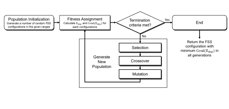
The genetic algorithm is implemented using the Sheffield Genetic Algorithm Toolbox49. There are 2000 individuals in the population, and each individual contains 14 filter thicknesses and 9 scintillator thicknesses. These thicknesses are floating-point numbers and encoded by bit strings to create the chromosomes, i.e., each individual contains 24 binary chromosomes. Considering the limitation of practical layer thickness, the lower limits of 0.01 mm and upper limits of 50 mm are set for the filters and the lower limits of 2 mm and upper limits of 50 mm are set for the scintillators, and 20 bits in one binary chromosome are used to ensure enough precision. All the filter thicknesses will be set to 0 while the thicknesses lower than 0.1 mm in iterations. The generation gap, mutation probability, and probability of crossover are 0.9, 0.01, and 0.7 respectively. The termination criteria is the iteration time reaching 300.
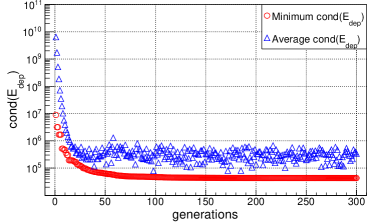
The minimum and average in the iterations is shown in FIG.2. The optimal is approximately, which has been significantly reduced compared with the unoptimized online FSS configuration, e.g., the CsI FSS reported previously36 with of (also 15 channels are taken into account). The optimal configuration obtained in iterations is listed in TABLE.2. The 0.01 mm accuracy is retained since the machining tolerance of GAGG crystal is 0.02 mm.
| Layer | Filter | Thickness (mm) | Sensor | Thickness (mm) |
| 1 | Al | 0.05 | S3590-08 | |
| 2 | Al | 0 | S3590-08 | |
| 3 | Al | 0 | S3590-08 | |
| 4 | Al | 2.82 | S3590-08 | |
| 5 | Al | 9.95 | S3590-08 | |
| 6 | Al | 24.34 | S3590-08 | |
| 7 | Cu | 3.53 | GAGG | 2 |
| 8 | Cu | 10.07 | GAGG | 2 |
| 9 | Cu | 4.73 | GAGG | 4.44 |
| 10 | Cu | 6.97 | GAGG | 13.04 |
| 11 | Cu | 0.57 | GAGG | 12.15 |
| 12 | Cu | 13 | GAGG | 33.74 |
| 13 | Cu | 1.14 | GAGG | 21.65 |
| 14 | Cu | 18.24 | GAGG | 33.2 |
| 15 | Cu | 34.52 | GAGG | 50 |
2.2 Unfolding spectrometer response
For testing the unfolding procedure and assessing the accuracy of unfolded radiation spectra, numerical experiments were conducted. From Eq.(2) and Eq.(5), the expected energy deposition , X-ray spectrum , energy-signal coefficients , and perturbation were calculated and modeled to simulate the channel data.
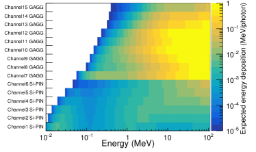
First, the optimized online FSS was modeled by using Monte Carlo code GEANT450 to obtain the accurate . The simulation model included the filters, sensors, scintillation photon detector, as well as PIN diode carrier board, collimator, shielding, and mechanical parts. The incident X-rays were a pencil-like beam distributing uniformly and randomly in a circle with a diameter of 6 mm, which was the diameter of the collimator. The energy range of incident X-rays was 10 keV to 200 MeV. In each energy bin, X-ray energies were uniformly and randomly sampled, and X-rays were simulated. The energy deposition curves of these X-ray beams impinging on the online FSS, i.e., , is shown in FIG.3.
The X-ray spectrum was modeled by
| (9) |
where is the on-axis betatron component, is the on-axis bremsstrahlung component, and is the background component51, 28, and the unit of is MeV. The parameters , , , , , , and define the curve shapes and fluence ratios of the three components, which were set to 12.47, 0.768, 7.52, , 3.88, 0.01, and 1 respectively. In this circumstance, the critical energy and peak energy of betatron radiation are 0.25 MeV and 0.1 MeV, and the fluence ratio of the background component is . Assuming the energy of X-rays ranged from 10 keV to 10 MeV and the total photon number was , the simulated energy depositions in the online FSS channels were obtained by multiplying the expected energy deposition and the photon numbers in each energy bin .
The can be estimated from Eq.(6) and Eq.(7). The GAGG crystals used are the GAGG-HL type manufactured by EPIC CRYSTAL Co. Ltd. with a light yield of 54000 photons/MeV. The light collection efficiency is approximately in the typical package and optical coupling conditions52. The maximum emission wavelength for GAGG is at around 530 nm47, and the quantum efficiency of PIN diodes, e.g., S3590-08, is approximately at the wavelength of 530 nm. Since the could vary due to the different scintillators, packages, and optical couplings, it is further calibrated experimentally as described in Section 2.3. The gains of FEE are the multiplying of the gains of TIAs and main amplifiers, which are determined to make the signal amplitudes conform to the dynamic range of each stage. The detailed discussion of can be found in Section 3.2 and the values are listed in TABLE.4.
The perturbation is mainly contributed by the statistical uncertainty and the electronic noise. The statistical uncertainty in PIN diode channels can be estimated by , where is the Fano factor, =3.62 eV is the energy for the formation of a charge carrier pair. The statistical uncertainties in GAGG channels are estimated from the previous calibration experiment conducted in our laboratory using radioactive sources52, i.e., . The electronic noise is hard to be modeled and quantitatively estimated, an electronic noise is applied to all the channels, where means the noise-free channel data. It is practically straightforward to achieve an electronic system with this noise level.
From the simulated channel data , the unfolded X-ray spectrum was further obtained by solving Eq.(8) using the expectation maximization method53. The degree of convergence was indicated as the normalized mean absolute distance (MAD) between the fitting channel data and the simulated channel data
| (10) |
where is the number of channels. With a constant function of one as the initial guess of , the fitting error from a different number of iterations is plotted in Fig.4(a). For the optimized GAGG array (denoted as the red cross), the fitting error decreases rapidly to a low level at the first steps, then reaches <1% after 50 steps. The divergence of the unfolded spectrum from the spectrum model function was also indicated as the normalized MAD between them
| (11) |
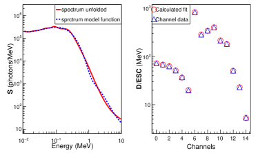
where is the energy bin number. As Fig.4(b) shows, the divergence can reach a minimum of 16% approximately in the energy range of 10 keV to 10 MeV when the fitting reaches convergence. The iteration step is chosen to be 100, which is large enough for observing the convergence property, a reasonable spectrum shape can be obtained and the response of the FSS is well fitted, as shown in FIG.5. It should be noted that the unfolding algorithms could significantly affect the unfolding results, and the expectation maximization method was chosen because it does not need many additional constraints and has a better universality.
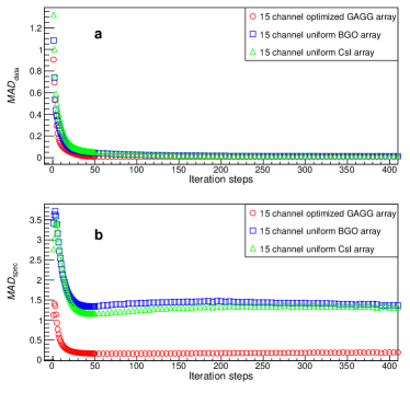
For comparative analysis, the CsI array proposed by Behm36 and the BGO array proposed by Rusby35 were also simulated following the aforementioned steps, and the channel number and noise level remained the same with the GAGG array, i.e., 15 channels. The thicknesses of BGO crystals were 0.2 cm. We found that the condition number of the CsI array and BGO array are and , and the minimum fitting errors are 115% and 133%, as shown in Fig.4. The unfolding error of the optimized GAGG array is significantly reduced compared with the CsI and BGO array of uniform thicknesses.
2.3 Quantitative calibration of the spectrometer response
The accurate determination of RM is of vital importance to get the precise spectra unfolding. In Eq.(5), can be obtained by Monte Carlo simulation precisely28, 36, 35. But the must be experimentally calibrated for the scintillator channels since the light yields and light collection efficiencies will vary depending on the scintillators, packages, and optical couplings and are difficult to be modeled and quantitatively calculated.
The most challenging thing in the experimental calibration campaign for and is to determine the energy depositions in the scintillators. Behm et al. performed the experimental calibration by measuring the scintillation signal resulting from a bremsstrahlung interaction, where the bremsstrahlung X-ray beam was theoretically calculated in GEANT4 by simulating the collision of a typical electron beam with a 9 mm thick piece of lead. Then the energy depositions in the CsI array were further determined in GEANT436. Rusby et al. calibrated their online FSS by exposing the detector to radiation sources for a long period of time and integrating the camera images. The energy depositions in the period of time were also determined by the GEANT4 simulation35.
In the optimized online FSS, the PIN diode S3590-08 is also used as the scintillation photon detector. Thanks to the 300 m depletion layer of S3590-08, the can be obtained by comparing the full-energy peaks of the radioactive sources, one of which directly irradiates the PIN diode S3590-08, and another of which irradiates the GAGG scintillator54. The energy depositions in the scintillators, i.e., the gamma-ray lines of the radioactive sources, can be determined accurately, thus providing more reliable calibration results.
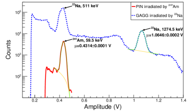
The 241Am with 59.5 keV line and 22Na with 1274.5 keV line are used in the calibration experiment. Charge sensitive pre-amplifiers, instead of TIA, were used to amplify the signals induced by radioactive sources. The spectrum measured during the experiment for one channel is shown in FIG.6 as an example.
Since the readout electronics are identical for GAGG and PIN diodes, according to Eq.(5), Eq.(6) and Eq.(7), can be calculated by
| (12) |
where and are fitting peak positions in the experimental spectrum, and are energy depositions in GAGG and PIN diodes, which are 1274.5 keV and 59.5 keV. For the spectrum shown in FIG.6, and are V and V, therefore = electrons/MeV.
3 Implementation
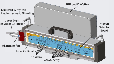
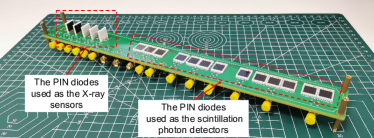
An online FSS prototype was built and calibrated using the methods described above. A schematic of the online FSS prototype is shown in FIG.7. The prototype comprises 6 channels of PIN diodes and 9 channels of GAGG scintillators as X-ray sensors, which are interleaved by the aluminum and copper filters. The collimator and laser sight are located in front of these PIN diode sensors, and the laser sight will be replaced by an outer collimator once the FSS is mounted. The scintillators are coupled with PIN diodes as the photon detectors. The signal output pins of the PIN diode are connected to the FEE board. The following DAQ board provides the capabilities of 16-channel waveform digitization and communication. And there is a power board providing the low noise V power and 70 V power for the FEE and PIN diode. The filter and X-ray sensors are shielded by a 1 cm thick layer of lead to avoid the interference of scattered X-rays, and there is a 1 cm diameter aperture allowing the X-ray incidence. The aperture is covered by a 50 m thick aluminum foil for electromagnetic shielding. The electronics are placed in an enclosed copper and aluminum box for electromagnetic shielding. The external interface only includes a 12 V power supply cable and a USB communication cable.
3.1 Filter and sensor unit
GAGG scintillators were chosen due to their good mechanical characteristics, non-hygroscopic properties, high light yields (30-70 ph/keV), and fast decay times (100 ns). The scintillators used have front faces of 1 cm 1 cm and variable thicknesses. The filter and scintillator configuration is listed in TABLE.3. The configuration of the prototype was obtained by the original version of our optimization code without proper constraints of the thicknesses, thus different from the configuration listed in TABLE.2. Nevertheless, the condition number of the prototype response matrix is , which is close to the optimized condition number presented in section 2.1 (compared with the uniform thickness configuration), and the improved performances are expected.
| Layer | Filter | Thickness (mm) | Sensor | Thickness (mm) |
| 1 | Al | 0.05 | S3590-08 | |
| 2 | Al | 0.59 | S3590-08 | |
| 3 | Al | 0 | S3590-08 | |
| 4 | Cu | 0.11 | S3590-08 | |
| 5 | Al | 0 | S3590-08 | |
| 6 | Al | 5.5 | S3590-08 | |
| 7 | Cu | 45.55 | GAGG | 2.6 |
| 8 | Cu | 2.63 | GAGG | 4.85 |
| 9 | Cu | 1.3 | GAGG | 8.67 |
| 10 | Cu | 11.59 | GAGG | 8.58 |
| 11 | Cu | 2.52 | GAGG | 23.26 |
| 12 | Cu | 2.06 | GAGG | 14.26 |
| 13 | Cu | 12.94 | GAGG | 9.49 |
| 14 | Cu | 3.16 | GAGG | 31.23 |
| 15 | Cu | 4.91 | GAGG | 19.58 |
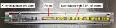
The reflection layers of scintillators are enhanced specular reflectors (ESRs), 65 m polymer with high reflectance (>98%) manufactured by 3M. The ESRs are cut into particular shapes allowing the scintillation light coupling from the side of the scintillators. The scintillators are fixed by an aluminum frame and interleaved by the filters, as shown in FIG.8.
The scintillation light output will be bright when the scintillators irradiated by laser-induced brilliant X-ray pulses, e.g., > scintillation photons ( MeV 54000 photons/MeV) per channel per pulse. The non-multiplying photon detector would be suitable for the scintillation light collection. To improve the light collection efficiency and the coupling stability, the PIN diode with a large sensitive area (1 cm 1 cm) is used as the photon detector, and the PIN diodes are directly coupled with the scintillators using the optical grease. Since there are 6 channels of PIN diodes used as the X-ray sensors, all the PIN diodes are mounted on one PIN diode carrier board vertically or horizontally, as shown in FIG.9.
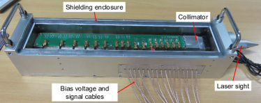
The sensors, filters, and PIN diodes are placed in an X-ray and electromagnetic shielding enclosure, along with the collimator and laser sight making up the filter and sensor unit as shown in FIG.10. The bias voltages and electric signals are applied or elicited using the coaxial cables.
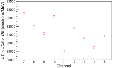
Using the calibration method described in section 2.3, the values of for 9 GAGG scintillation channels were experimentally calibrated as shown in FIG.11. The error bars are not visible in this figure due to the low peak fitting error.
3.2 Electronics unit
The PIN diode signal is fed to a trans-impedance amplifier (TIA) via the alternating current (AC) coupling, and a standard high-speed amplifier OPA657 is adopted as the TIA amplifier. A 2000 ohms resistor connects the cathode of the PIN diode to the ground as the direct-current (DC) path, which can restrain the current of the PIN diode and increases the system reliability. The TIA is followed by the main amplifier, adjusting the voltage amplitude to match the DAQ dynamic range. In addition to 16-channel TIAs and main amplifiers, the FEE board includes a trigger circuit to generate the inner trigger signal for the DAQ.
Gains of the FEE circuit are determined to ensure the signal amplitude is in line with the dynamic range in each circuit stage. First, the energy depositions per pulse in the PIN diodes and scintillators are calculated using GEANT4. The X-ray source has a spectrum as Eq.(9) modeled, photon fluence of photons/sr/pulse, and located at 1 meter away from the collimator of online FSS. Thus the number of X-ray photons passing through the collimating aperture is per pulse.
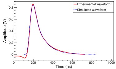
Then, the temporal waveforms are calculated using the transient response model, including the GAGG scintillation light, PIN diodes output current, and the output voltage of each circuit stage. The PIN diode is treated as a two-order Butterworth low-pass filter (LPF) with a -3 dB bandwidth of 40 MHz55. The transient response of the GAGG scintillator can be expressed as a single exponential decay signal with a decay time of 100 ns, and the TIA can also be treated as a two-order Butterworth LPF with -3 dB bandwidth of 52, where is the gain bandwidth product of OPA657, is the feedback resistance, and is the input capacitance of the TIA. is mainly contributed by the terminal capacitance of PIN Diodes and the stray capacitance of cables in the order of 100 pF. The main amplifier is designed to be an inverting two-order voltage-controlled voltage sources LPF with a -3 dB bandwidth of 10 MHz. The simulated waveform of the FEE output is plotted along with the experimental waveform measured in the laser-plasma experiment in Fig.12. The simulated waveform has preferably coherence with the experimental waveform, e.g., the relative difference of the peak amplitudes is less than 2% when the integrals from 130 ns to 700 ns are equal (with the same energy depositions), thus validating the built transient response model.
Since the voltage output swing of TIA is 0-3 V and the DAQ input dynamic is 1 V, the gains of the main amplifier are determined to make the dynamic range of the DAQ fully used, which is 0.32. Then, using the transient response model, the gains of TIA are determined to make the peak amplitudes of 15-channel TIA outputs in the order of 500 millivolts, which are listed in TABLE.4. The main purpose of this section is to describe the hardware design methods. As the X-ray fluence varies greatly in different laser-plasma experiments, the FEE is designed to be a plug-in module thus the gains can be determined following the methods and easily changed.
| channels | 1-6 | 7-12 | 13-15 |
| in ohm | 200.32 | 2000.32 | 10000.32 |
The gains of TIAs and main amplifiers are listed on the left and right sides of multiplication signs respectively.
For reserving the temporal waveform information and further implementing the flexible digital signal processing technique, a commercial 16-channel high-speed analog-digital conversion module based on DRS4 chips is adopted as the DAQ system. The DAQ provides a 1 GHz sample rate, 1024 sample acquisition window (1.024 s at 1 GHz), and 30 MB/s transfer rate (USB2.0 protocol). Since the decay time of GAGG is 100 ns, a 1.024 s acquisition window can record the waveform completely. A higher repetition rate of hundred kHz should be allowed for the online FSS system, but the repetition rate is limited to 1 kHz approximately by the DAQ data transfer rate, i.e., 30 MB/s divided by "16 channel12 bit/sample1024 sample/channel/pulse" equals 1220 pulse/s. For future campaigns where higher repetition rates may be available, the online FSS system can be easily changed to a faster one by upgrading the data transfer protocol.
4 Preliminary Experiment
To test the functionality of this online FSS design, the prototype was deployed on a positron experiment, where strong bremsstrahlung was generated. The experiment was conducted at the SILEX-II laser, a complete optical parametric chirped-pulse amplification (OPCPA) laser operating at a wavelength of 800 nm56. The laser energy on targets is 27 2.7 J (RMS), and the laser pulse duration is 34.5 2.5 fs (RMS), thus the on-target laser power is around 1 PW. In the experiment, the laser interacted with a gas cell to generate high-energy electron beams via wakefield acceleration. The gas cell was 800 m in length and filled by 128 kPa nitrogen. The energetic electron beam then propagated through a converter material (2 mm tungsten) mounted 10 mm behind the gas cell to generate the bremsstrahlung gamma-ray beams. The online FSS prototype was located 1.5 m from the converter at an angle of 30∘ from the laser propagation direction, as shown in Fig.13.
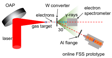
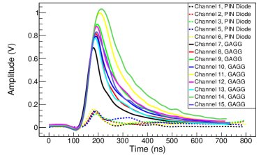
Fig.14 represents the measured waveforms in one shot. The disturbance induced by electromagnetic pulse could be observed in these waveforms, and the waveform of channel 4 was missed due to the loose contact. Nevertheless, the X-ray spectrum was still unfolded as a preliminary demonstration.
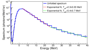
The waveforms were integrated from 130 ns to 700 ns for the GAGG channels and from 130 ns to 200 ns for the PIN diodes channels, as the experimental channel data . The was obtained by Geant4 simulation and the was calibrated and calculated according to Eq.(6) and Eq.(7). The spectrum was obtained by solving Eq.(8) using the expectation maximization method with 100 steps of iteration, as shown in Fig.15, and the transmission of the Al flange had been taken into account. The error bars were given by adding random noises to the channel data and repeating the unfolding process times. Considering the unperfect electromagnetic shielding, we approximated the random noises as 5% of the channel data. The spectral shape was consistent with a typical high power laser-induced bremsstrahlung spectrum57, and could be well fitted as a two effective temperature distribution with exponential effective temperatures of the form . The lower effective temperature and the higher effective temperature were fitted between 7-23 MeV and 23-45 MeV respectively, yielding MeV and MeV.
5 CONCLUSION
In conclusion, to alleviate the ill-posed system of FSS, an optimization method using the genetic algorithm is proposed. The condition number of RM is used as the figure of merit for optimization. We use not only high-density GAGG scintillators but also silicon PIN diodes, to improve the unfolding accuracy in tens of keV to tens of MeV energy bands. The Monto Carlo simulations show that the optimized FSS can provide a measurement of a typical spectrum from tens keV to tens MeV with a significantly improved accuracy.
We have implemented the optimized online FSS. PIN diodes are used as the scintillation photon detector to improve the light collection efficiency and coupling stability, thus further improving the unfolding accuracy. The usage of PIN diodes also promised the quantitative calibration of the light yields and light collection efficiencies. The electric signals from PIN diodes are amplified and digitalized by a homemade FEE module and commercial DAQ card. The repetition rate of the online FSS prototype is 1 kHz and can be further improved by increasing the data transfer rate of the DAQ card, e.g., using the 80 MB/s optical link interface or USB 3.0 interface. Since the IP scanner or high-speed CCD/CMOS are no longer needed, this online FSS system has the advantages of low cost and compactness as well.
We have also shown the functionality of the online FSS prototype through a preliminary experiment. The unfolding spectrum consists of a typical bremsstrahlung spectrum, and the temperature measured is in good agreement with the simulated one in the tens of MeV band. In the future, we will carry out more system test experiments and improve the electromagnetic compatibility, to implement a low-noise system with high unfolding accuracy. With the increasing demands of the high repetition rate and high accuracy, future laser-plasma experiments and application research would benefit from this optimized, integrated, compact, and low-cost online FSS technique.
Acknowledgements
The authors thank Zhimeng Zhang and Bo Zhang for their assistance in the experiment. This work is supported by the Natural Science Foundation of China (Grant No. 12004353, 11975214, 11991071, 11905202, 12175212, 12120101005), and Key Laboratory Foundation of The Sciences and Technology on Plasma Physics Laboratory (Grant No.6142A04200103 and 6142A0421010).
References
- 1 E. Esarey, C. B. Schroeder, and W. P. Leemans, “Physics of laser-driven plasma-based electron accelerators,” Reviews of Modern Physics, vol. 81, pp. 1229–1285, Aug. 2009.
- 2 E. Esarey, B. A. Shadwick, P. Catravas, and W. P. Leemans, “Synchrotron radiation from electron beams in plasma-focusing channels,” Physical Review E, vol. 65, p. 056505, May 2002.
- 3 K. Ta Phuoc, S. Corde, C. Thaury, V. Malka, A. Tafzi, J. P. Goddet, R. C. Shah, S. Sebban, and A. Rousse, “All-optical Compton gamma-ray source,” Nature Photonics, vol. 6, pp. 308–311, May 2012.
- 4 G. Sarri, D. Corvan, W. Schumaker, J. Cole, A. Di Piazza, H. Ahmed, C. Harvey, C. Keitel, K. Krushelnick, S. Mangles, Z. Najmudin, D. Symes, A. Thomas, M. Yeung, Z. Zhao, and M. Zepf, “Ultrahigh Brilliance Multi-MeV $\ensuremath{\gamma}$-Ray Beams from Nonlinear Relativistic Thomson Scattering,” Physical Review Letters, vol. 113, no. 22, p. 224801, 2014. Publisher: American Physical Society.
- 5 W. Yan, C. Fruhling, G. Golovin, D. Haden, J. Luo, P. Zhang, B. Zhao, J. Zhang, C. Liu, M. Chen, S. Chen, S. Banerjee, and D. Umstadter, “High-order multiphoton Thomson scattering,” Nature Photonics, vol. 11, pp. 514–520, Aug. 2017. Number: 8 Publisher: Nature Publishing Group.
- 6 S. Cipiccia, S. M. Wiggins, R. P. Shanks, M. R. Islam, G. Vieux, R. C. Issac, E. Brunetti, B. Ersfeld, G. H. Welsh, M. P. Anania, D. Maneuski, N. R. C. Lemos, R. A. Bendoyro, P. P. Rajeev, P. Foster, N. Bourgeois, T. P. A. Ibbotson, P. A. Walker, V. O. Shea, J. M. Dias, and D. A. Jaroszynski, “A tuneable ultra-compact high-power, ultra-short pulsed, bright gamma-ray source based on bremsstrahlung radiation from laser-plasma accelerated electrons,” Journal of Applied Physics, vol. 111, no. 6, p. 063302, 2012. Publisher: American Institute of Physics.
- 7 S. Corde, K. Ta Phuoc, G. Lambert, R. Fitour, V. Malka, A. Rousse, A. Beck, and E. Lefebvre, “Femtosecond x rays from laser-plasma accelerators,” Reviews of Modern Physics, vol. 85, pp. 1–48, Jan. 2013.
- 8 F. Albert and A. G. R. Thomas, “Applications of laser wakefield accelerator-based light sources,” Plasma Physics and Controlled Fusion, vol. 58, p. 103001, Sept. 2016. Publisher: IOP Publishing.
- 9 B. Guo, X. Zhang, J. Zhang, J. Hua, C.-H. Pai, C. Zhang, H.-H. Chu, W. Mori, C. Joshi, J. Wang, and W. Lu, “High-resolution phase-contrast imaging of biological specimens using a stable betatron X-ray source in the multiple-exposure mode,” Scientific Reports, vol. 9, p. 7796, May 2019. Place: London Publisher: Nature Publishing Group WOS:000468859400011.
- 10 C. P. Jones, C. M. Brenner, C. A. Stitt, C. Armstrong, D. R. Rusby, S. R. Mirfayzi, L. A. Wilson, A. Alejo, H. Ahmed, R. Allott, N. M. H. Butler, R. J. Clarke, D. Haddock, C. Hernandez-Gomez, A. Higginson, C. Murphy, M. Notley, C. Paraskevoulakos, J. Jowsey, P. McKenna, D. Neely, S. Kar, and T. B. Scott, “Evaluating laser-driven Bremsstrahlung radiation sources for imaging and analysis of nuclear waste packages,” Journal of Hazardous Materials, vol. 318, pp. 694–701, Nov. 2016.
- 11 Y. Yang, Y.-C. Wu, L. Li, S.-Y. Zhang, K.-G. Dong, T.-K. Zhang, M.-H. Yu, X.-H. Zhang, B. Zhu, F. Tan, Y.-H. Yan, G. Li, W. Fan, F. Lu, Z.-Q. Zhao, W.-M. Zhou, L.-F. Cao, and Y.-Q. Gu, “Design and characterization of high energy micro-CT with a laser-based X-ray source,” Results in Physics, vol. 14, p. 102382, Sept. 2019. Place: Amsterdam Publisher: Elsevier WOS:000485104100154.
- 12 R. Tommasini, C. Bailey, D. K. Bradley, M. Bowers, H. Chen, J. M. Di Nicola, P. Di Nicola, G. Gururangan, G. N. Hall, C. M. Hardy, D. Hargrove, M. Hermann, M. Hohenberger, J. P. Holder, W. Hsing, N. Izumi, D. Kalantar, S. Khan, J. Kroll, O. L. Landen, J. Lawson, D. Martinez, N. Masters, J. R. Nafziger, S. R. Nagel, A. Nikroo, J. Okui, D. Palmer, R. Sigurdsson, S. Vonhof, R. J. Wallace, and T. Zobrist, “Short pulse, high resolution, backlighters for point projection high-energy radiography at the National Ignition Facility,” Physics of Plasmas, vol. 24, p. 053104, May 2017. Publisher: American Institute of Physics.
- 13 C. Tian, M. Yu, L. Shan, Y. Wu, T. Zhang, B. Bi, F. Zhang, Q. Zhang, D. Liu, W. Wang, Z. Yuan, S. Yang, L. Yang, W. Zhou, Y. Gu, and B. Zhang, “Radiography of direct drive double shell targets with hard x-rays generated by a short pulse laser,” Nuclear Fusion, vol. 59, p. 046012, Feb. 2019. Publisher: IOP Publishing.
- 14 M. Downer, R. Zgadzaj, A. Debus, U. Schramm, and M. Kaluza, “Diagnostics for plasma-based electron accelerators,” Reviews of Modern Physics, vol. 90, p. 035002, Aug. 2018.
- 15 S. Kneip, S. R. Nagel, C. Bellei, N. Bourgeois, A. E. Dangor, A. Gopal, R. Heathcote, S. P. D. Mangles, J. R. Marquès, A. Maksimchuk, P. M. Nilson, K. T. Phuoc, S. Reed, M. Tzoufras, F. S. Tsung, L. Willingale, W. B. Mori, A. Rousse, K. Krushelnick, and Z. Najmudin, “Observation of Synchrotron Radiation from Electrons Accelerated in a Petawatt-Laser-Generated Plasma Cavity,” Physical Review Letters, vol. 100, p. 105006, Mar. 2008. Publisher: American Physical Society.
- 16 S. Kneip, C. McGuffey, J. L. Martins, S. F. Martins, C. Bellei, V. Chvykov, F. Dollar, R. Fonseca, C. Huntington, G. Kalintchenko, A. Maksimchuk, S. P. D. Mangles, T. Matsuoka, S. R. Nagel, C. a. J. Palmer, J. Schreiber, K. T. Phuoc, A. G. R. Thomas, V. Yanovsky, L. O. Silva, K. Krushelnick, and Z. Najmudin, “Bright spatially coherent synchrotron X-rays from a table-top source,” Nature Physics, vol. 6, pp. 980–983, Dec. 2010. Number: 12 Publisher: Nature Publishing Group.
- 17 Y. H. Yan, L. Wei, X. L. Wen, Y. C. Wu, Z. Q. Zhao, B. Zhang, B. Zhu, W. Hong, L. F. Cao, Z. Yao, and Y. Q. Gu, “Calibration and Monte Carlo simulation of a single-photon counting charge-coupled device for single-shot X-ray spectrum measurements,” Chinese Optics Letters, vol. 11, p. 4, Nov. 2013.
- 18 C. Stoeckl, W. Theobald, T. C. Sangster, M. H. Key, P. Patel, B. B. Zhang, R. Clarke, S. Karsch, and P. Norreys, “Operation of a single-photon-counting x-ray charge-coupled device camera spectrometer in a petawatt environment,” Review of Scientific Instruments, vol. 75, pp. 3705–3707, Oct. 2004. Patent Number: 2 Place: Melville Publisher: Amer Inst Physics WOS:000224755900097.
- 19 M.-h. Yu, G.-y. Hu, N. An, F. Qian, Y.-c. Wu, X.-d. Zhang, Y.-q. Gu, Q.-p. Wang, and J. Zheng, “Hard x-ray transmission curved crystal spectrometers (10-100 keV) for laser fusion experiments at the ShenGuang-III laser facility,” High Power Laser Science and Engineering, vol. 4, p. e2, Feb. 2016.
- 20 Z. Chi, L. Yan, Z. Zhang, Z. Zhou, L. Zheng, D. Wang, Q. Tian, W. Wang, Z. Nie, J. Zhang, Y. Du, J. Hua, J. Shi, C. Pai, W. Lu, W. Huang, H. Chen, and C. Tang, “Diffraction based method to reconstruct the spectrum of the Thomson scattering x-ray source,” Review of Scientific Instruments, vol. 88, p. 045110, Apr. 2017.
- 21 J. Wen, “Diagnostics for ultrashort X-ray pulses using silicon trackers,” Nuclear Instruments and Methods in Physics Research Section A: Accelerators, Spectrometers, Detectors and Associated Equipment, vol. 1014, p. 165754, Oct. 2021. Publisher: North-Holland.
- 22 S. Singh, R. Versaci, A. L. Garcia, L. Morejon, A. Ferrari, M. Molodtsova, R. Schwengner, D. Kumar, and T. Cowan, “Compact high energy x-ray spectrometer based on forward Compton scattering for high intensity laser plasma experiments,” Review of Scientific Instruments, vol. 89, p. 7, Aug. 2018.
- 23 S. Cipiccia, S. M. Wiggins, D. Maneuski, E. Brunetti, G. Vieux, X. Yang, R. C. Issac, G. H. Welsh, M. Anania, M. R. Islam, B. Ersfeld, R. Montgomery, G. Smith, M. Hoek, D. J. Hamilton, N. R. C. Lemos, D. R. Symes, P. P. Rajeev, V. O. Shea, J. M. Dias, and D. A. Jaroszynski, “Compton scattering for spectroscopic detection of ultra-fast, high flux, broad energy range X-rays,” Review of Scientific Instruments, vol. 84, p. 113302, Nov. 2013. Publisher: American Institute of Physics.
- 24 A. E. Gehring, M. A. Espy, T. J. Haines, J. F. Hunter, N. S. P. King, M. J. Manard, F. E. Merrill, G. L. Morgan, R. Sedillo, R. Trainham, A. V. Urbaitis, and P. Volegov, “Determining x-ray spectra of radiographic sources with a Compton spectrometer,” in Radiation Detectors: Systems and Applications Xv (G. P. Grim and H. B. Barber, eds.), vol. 9215, p. UNSP 921508, Bellingham: Spie-Int Soc Optical Engineering, 2014. ISSN: 0277-786X WOS:000344466500006.
- 25 D. J. Corvan, G. Sarri, and M. Zepf, “Design of a compact spectrometer for high-flux MeV gamma-ray beams,” Review of Scientific Instruments, vol. 85, p. 065119, June 2014. Place: Melville Publisher: Amer Inst Physics WOS:000339010500073.
- 26 D. Haden, G. Golovin, W. Yan, C. Fruhling, P. Zhang, B. Zhao, S. Banerjee, and D. Umstadter, “High energy X-ray Compton spectroscopy via iterative reconstruction,” Nuclear Instruments & Methods in Physics Research Section a-Accelerators Spectrometers Detectors and Associated Equipment, vol. 951, p. 163032, Jan. 2020. Place: Amsterdam Publisher: Elsevier WOS:000502088900023.
- 27 C. Courtois, R. Edwards, A. C. La Fontaine, C. Aedy, S. Bazzoli, J. L. Bourgade, J. Gazave, J. M. Lagrange, O. Landoas, L. Le Dain, D. Mastrosimone, N. Pichoff, G. Pien, and C. Stoeckl, “Characterisation of a MeV Bremsstrahlung x-ray source produced from a high intensity laser for high areal density object radiography,” Physics of Plasmas, vol. 20, p. 9, Aug. 2013.
- 28 J. H. Jeon, K. Nakajima, H. T. Kim, Y. J. Rhee, V. B. Pathak, M. H. Cho, J. H. Shin, B. J. Yoo, C. Hojbota, S. H. Jo, K. W. Shin, J. H. Sung, S. K. Lee, B. I. Cho, I. W. Choi, and C. H. Nam, “A broadband gamma-ray spectrometry using novel unfolding algorithms for characterization of laser wakefield-generated betatron radiation,” Review of Scientific Instruments, vol. 86, p. 9, Dec. 2015.
- 29 A. Hannasch, A. Laso Garcia, M. LaBerge, R. Zgadzaj, A. Köhler, J. P. Couperus Cabadağ, O. Zarini, T. Kurz, A. Ferrari, M. Molodtsova, L. Naumann, T. E. Cowan, U. Schramm, A. Irman, and M. C. Downer, “Compact spectroscopy of keV to MeV X-rays from a laser wakefield accelerator,” Scientific Reports, vol. 11, p. 14368, Dec. 2021.
- 30 A. L. Meadowcroft, C. D. Bentley, and E. N. Stott, “Evaluation of the sensitivity and fading characteristics of an image plate system for x-ray diagnostics,” Review of Scientific Instruments, vol. 79, p. 113102, Nov. 2008.
- 31 T. Bonnet, M. Comet, D. Denis-Petit, F. Gobet, F. Hannachi, M. Tarisien, M. Versteegen, and M. M. Aléonard, “Response functions of imaging plates to photons, electrons and 4He particles,” Review of Scientific Instruments, vol. 84, p. 103510, Oct. 2013. Publisher: American Institute of Physics.
- 32 P. W. Hatfield, J. A. Gaffney, G. J. Anderson, S. Ali, L. Antonelli, S. Başeğmez du Pree, J. Citrin, M. Fajardo, P. Knapp, B. Kettle, B. Kustowski, M. J. MacDonald, D. Mariscal, M. E. Martin, T. Nagayama, C. A. J. Palmer, J. L. Peterson, S. Rose, J. J. Ruby, C. Shneider, M. J. V. Streeter, W. Trickey, and B. Williams, “The data-driven future of high-energy-density physics,” Nature, vol. 593, pp. 351–361, May 2021.
- 33 T. Ma, D. Mariscal, R. Anirudh, T. Bremer, B. Z. Djordjevic, T. Galvin, E. Grace, S. Herriot, S. Jacobs, B. Kailkhura, R. Hollinger, J. Kim, S. Liu, J. Ludwig, D. Neely, J. J. Rocca, G. G. Scott, R. A. Simpson, B. S. Spears, T. S. Spinka, K. Swanson, J. J. Thiagarajan, B. Van Essen, S. Wang, S. C. Wilks, G. J. Williams, J. Zhang, M. C. Herrmann, and C. Haefner, “Accelerating the rate of discovery: toward high-repetition-rate HED science,” vol. 63, no. 10, p. 104003.
- 34 C. Grupen and B. Shwartz, Particle Detectors. Cambridge Monographs on Particle Physics, Nuclear Physics and Cosmology, Cambridge: Cambridge University Press, 2 ed., 2008.
- 35 D. R. Rusby, C. D. Armstrong, C. M. Brenner, R. J. Clarke, P. McKenna, and D. Neely, “Novel scintillator-based x-ray spectrometer for use on high repetition laser plasma interaction experiments,” Review of Scientific Instruments, vol. 89, p. 8, July 2018.
- 36 K. T. Behm, J. M. Cole, A. S. Joglekar, E. Gerstmayr, J. C. Wood, C. D. Baird, T. G. Blackburn, M. Duff, C. Harvey, A. Ilderton, S. Kuschel, S. P. D. Mangles, M. Marklund, P. McKenna, C. D. Murphy, Z. Najmudin, K. Poder, C. P. Ridgers, G. Sarri, G. M. Samarin, D. Symes, J. Warwick, M. Zepf, K. Krushelnick, and A. G. R. Thomas, “A spectrometer for ultrashort gamma-ray pulses with photon energies greater than 10 MeV,” Review of Scientific Instruments, vol. 89, p. 9, Nov. 2018.
- 37 V. Stránský, V. Istokskaia, R. Versaci, L. Giuffrida, A. Cimmino, D. Margarone, and V. Olšovcová, “Development, optimization, and calibration of an active electromagnetic calorimeter for pulsed radiation spectrometry,” Journal of Instrumentation, vol. 16, p. P08060, Aug. 2021.
- 38 V. Istokskaia, V. Stránský, L. Giuffrida, R. Versaci, F. Grepl, M. Tryus, A. Velyhan, R. Dudžák, J. Krása, M. Krupka, S. Singh, D. Neely, V. Olšovcová, and D. Margarone, “Experimental tests and signal unfolding of a scintillator calorimeter for laser-plasma characterization,” Journal of Instrumentation, vol. 16, pp. T02006–T02006, Feb. 2021.
- 39 J. M. Cole, K. T. Behm, E. Gerstmayr, T. G. Blackburn, J. C. Wood, C. D. Baird, M. J. Duff, C. Harvey, A. Ilderton, A. S. Joglekar, K. Krushelnick, S. Kuschel, M. Marklund, P. McKenna, C. D. Murphy, K. Poder, C. P. Ridgers, G. M. Samarin, G. Sarri, D. R. Symes, A. G. R. Thomas, J. Warwick, M. Zepf, Z. Najmudin, and S. P. D. Mangles, “Experimental Evidence of Radiation Reaction in the Collision of a High-Intensity Laser Pulse with a Laser-Wakefield Accelerated Electron Beam,” Physical Review X, vol. 8, p. 011020, Feb. 2018. Place: College Pk Publisher: Amer Physical Soc WOS:000424381700001.
- 40 K. Poder, M. Tamburini, G. Sarri, A. Di Piazza, S. Kuschel, C. Baird, K. Behm, S. Bohlen, J. Cole, D. Corvan, M. Duff, E. Gerstmayr, C. Keitel, K. Krushelnick, S. Mangles, P. McKenna, C. Murphy, Z. Najmudin, C. Ridgers, G. Samarin, D. Symes, A. Thomas, J. Warwick, and M. Zepf, “Experimental Signatures of the Quantum Nature of Radiation Reaction in the Field of an Ultraintense Laser,” Physical Review X, vol. 8, p. 031004, July 2018. Publisher: American Physical Society.
- 41 C. I. D. Underwood, C. D. Baird, C. D. Murphy, C. D. Armstrong, C. Thornton, O. J. Finlay, M. J. V. Streeter, M. P. Selwood, N. Brierley, S. Cipiccia, J.-N. Gruse, P. McKenna, Z. Najmudin, D. Neely, D. Rusby, D. R. Symes, and C. M. Brenner, “Development of control mechanisms for a laser wakefield accelerator-driven bremsstrahlung x-ray source for advanced radiographic imaging,” Plasma Physics and Controlled Fusion, vol. 62, no. 12, p. 124002, 2020. Publisher: IOP Publishing.
- 42 D. Goldberg, “Genetic Algorithm in Search, Optimization, and Machine Learning,” Addison-Wesley, Reading, Massachusetts, vol. xiii, Jan. 1989.
- 43 M. Bitossi, R. Paoletti, and D. Tescaro, “Ultra-Fast Sampling and Data Acquisition Using the DRS4 Waveform Digitizer,” Ieee Transactions on Nuclear Science, vol. 63, pp. 2309–2316, Aug. 2016. Patent Number: 2 Place: Piscataway Publisher: Ieee-Inst Electrical Electronics Engineers Inc WOS:000382469200007.
- 44 D. L. Fehl, G. A. Chandler, W. A. Stygar, R. E. Olson, C. L. Ruiz, J. J. Hohlfelder, L. P. Mix, F. Biggs, M. Berninger, P. O. Frederickson, and R. Frederickson, “Characterization and error analysis of an N X N unfolding procedure applied to filtered, photoelectric x-ray detector arrays. I. Formulation and testing,” Physical Review Special Topics-Accelerators and Beams, vol. 13, p. 120402, Dec. 2010. Place: College Pk Publisher: Amer Physical Soc WOS:000285793400001.
- 45 D. L. Fehl, G. A. Chandler, W. A. Stygar, R. E. Olson, C. L. Ruiz, J. J. Hohlfelder, L. P. Mix, F. Biggs, M. Berninger, P. O. Frederickson, and R. Frederickson, “Characterization and error analysis of an N X N unfolding procedure applied to filtered, photoelectric x-ray detector arrays. II. Error analysis and generalization,” Physical Review Special Topics-Accelerators and Beams, vol. 13, p. 120403, Dec. 2010. Place: College Pk Publisher: Amer Physical Soc WOS:000285793400002.
- 46 M. Reginatto, “Overview of spectral unfolding techniques and uncertainty estimation,” Radiation Measurements, vol. 45, pp. 1323–1329, Dec. 2010. Place: Oxford Publisher: Pergamon-Elsevier Science Ltd WOS:000286349000058.
- 47 J. Iwanowska, L. Swiderski, T. Szczesniak, P. Sibczynski, M. Moszynski, M. Grodzicka, K. Kamada, K. Tsutsumi, Y. Usuki, T. Yanagida, and A. Yoshikawa, “Performance of cerium-doped Gd3Al2Ga3O12 (GAGG:Ce) scintillator in gamma-ray spectrometry,” Nuclear Instruments & Methods in Physics Research Section a-Accelerators Spectrometers Detectors and Associated Equipment, vol. 712, pp. 34–40, June 2013.
- 48 A. Owens and A. Peacock, “Compound semiconductor radiation detectors,” Nuclear Instruments and Methods in Physics Research Section A: Accelerators, Spectrometers, Detectors and Associated Equipment, vol. 531, pp. 18–37, Sept. 2004.
- 49 A. Chipperfield, P. Fleming, and H. Pohlheim, “A genetic algorithm toolbox for MATLAB,” Proceedings of the International Conference on Systems Engineering, pp. 200–207, Apr. 1994.
- 50 S. Agostinelli, J. Allison, K. Amako, J. Apostolakis, H. Araujo, P. Arce, M. Asai, D. Axen, S. Banerjee, G. Barrand, F. Behner, L. Bellagamba, J. Boudreau, L. Broglia, A. Brunengo, H. Burkhardt, S. Chauvie, J. Chuma, R. Chytracek, G. Cooperman, G. Cosmo, P. Degtyarenko, A. Dell’Acqua, G. Depaola, D. Dietrich, R. Enami, A. Feliciello, C. Ferguson, H. Fesefeldt, G. Folger, F. Foppiano, A. Forti, S. Garelli, S. Giani, R. Giannitrapani, D. Gibin, J. J. Gómez Cadenas, I. González, G. Gracia Abril, G. Greeniaus, W. Greiner, V. Grichine, A. Grossheim, S. Guatelli, P. Gumplinger, R. Hamatsu, K. Hashimoto, H. Hasui, A. Heikkinen, A. Howard, V. Ivanchenko, A. Johnson, F. W. Jones, J. Kallenbach, N. Kanaya, M. Kawabata, Y. Kawabata, M. Kawaguti, S. Kelner, P. Kent, A. Kimura, T. Kodama, R. Kokoulin, M. Kossov, H. Kurashige, E. Lamanna, T. Lampén, V. Lara, V. Lefebure, F. Lei, M. Liendl, W. Lockman, F. Longo, S. Magni, M. Maire, E. Medernach, K. Minamimoto, P. Mora de Freitas, Y. Morita, K. Murakami, M. Nagamatu, R. Nartallo, P. Nieminen, T. Nishimura, K. Ohtsubo, M. Okamura, S. O’Neale, Y. Oohata, K. Paech, J. Perl, A. Pfeiffer, M. G. Pia, F. Ranjard, A. Rybin, S. Sadilov, E. Di Salvo, G. Santin, T. Sasaki, N. Savvas, Y. Sawada, S. Scherer, S. Sei, V. Sirotenko, D. Smith, N. Starkov, H. Stoecker, J. Sulkimo, M. Takahata, S. Tanaka, E. Tcherniaev, E. Safai Tehrani, M. Tropeano, P. Truscott, H. Uno, L. Urban, P. Urban, M. Verderi, A. Walkden, W. Wander, H. Weber, J. P. Wellisch, T. Wenaus, D. C. Williams, D. Wright, T. Yamada, H. Yoshida, and D. Zschiesche, “Geant4—a simulation toolkit,” Nuclear Instruments and Methods in Physics Research Section A: Accelerators, Spectrometers, Detectors and Associated Equipment, vol. 506, pp. 250–303, July 2003.
- 51 W. Schumaker, G. Sarri, M. Vargas, Z. Zhao, K. Behm, V. Chvykov, B. Dromey, B. Hou, A. Maksimchuk, J. Nees, V. Yanovsky, M. Zepf, A. G. R. Thomas, and K. Krushelnick, “Measurements of high-energy radiation generation from laser-wakefield accelerated electron beams,” Physics of Plasmas, vol. 21, p. 056704, May 2014. WOS:000337107200133.
- 52 J.-X. Wen, X.-T. Zheng, J.-D. Yu, Y.-P. Che, D.-X. Yang, H.-Z. Gao, Y.-F. Jin, X.-Y. Long, Y.-H. Liu, D.-C. Xu, Y.-C. Zhang, M. Zeng, Y. Tian, H. Feng, Z. Zeng, J.-R. Cang, Q. Wu, Z.-Q. Zhao, B.-B. Zhang, P. An, and GRID collaboration, “Compact CubeSat Gamma-ray detector for GRID mission,” Nuclear Science and Techniques, vol. 32, p. 99, Sept. 2021.
- 53 L. Zhang, G. Zhang, Z. Chen, Y. Xing, J. Cheng, and Y. Xiao, “X-ray spectrum estimation from transmission measurements using the expectation maximization method,” in 2007 Ieee Nuclear Science Symposium Conference Record, Vols 1-11, pp. 3089–3093, 2007. ISSN: 1095-7863 WOS:000257380402113.
- 54 L. Meng, D. Ramsden, V. Chirkin, V. Potapov, O. Ivanov, and S. Ignatov, “The design and performance of a large-volume spherical CsI(Tl) scintillation counter for gamma-ray spectroscopy,” Nuclear Instruments and Methods in Physics Research Section A: Accelerators, Spectrometers, Detectors and Associated Equipment, vol. 485, pp. 468–476, June 2002.
- 55 HAMAMTSU, “S3590-08 datasheet.”
- 56 W. Hong, S. He, J. Teng, Z. Deng, Z. Zhang, F. Lu, B. Zhang, B. Zhu, Z. Dai, B. Cui, Y. Wu, D. Liu, W. Qi, J. Jiao, F. Zhang, Z. Yang, F. Zhang, B. Bi, X. Zeng, K. Zhou, Y. Zuo, X. Huang, N. Xie, Y. Guo, J. Su, D. Han, Y. Mao, L. Cao, W. Zhou, Y. Gu, F. Jing, B. Zhang, H. Cai, M. He, W. Zheng, S. Zhu, W. Ma, D. Wang, Y. Shou, X. Yan, B. Qiao, Y. Zhang, C. Zhong, X. Yuan, and W. Wei, “Commissioning experiment of the high-contrast SILEX-ii multi-petawatt laser facility,” vol. 6, no. 6, p. 064401.
- 57 C. Zulick, B. Hou, F. Dollar, A. Maksimchuk, J. Nees, A. G. R. Thomas, Z. Zhao, and K. Krushelnick, “High resolution bremsstrahlung and fast electron characterization in ultrafast intense laser–solid interactions,” vol. 15, no. 12, p. 123038. Publisher: IOP Publishing.