Engineered zero-dispersion microcombs using CMOS-ready photonics
Abstract
Normal group velocity dispersion (GVD) microcombs offer high comb line power and high pumping efficiency compared to bright pulse microcombs. The recent demonstration of normal GVD microcombs using CMOS-foundry-produced microresonators is an important step towards scalable production. However, the chromatic dispersion of CMOS devices is large and impairs generation of broadband microcombs. Here, we report the development of a microresonator in which GVD is reduced due to a couple-ring resonator configuration. Operating in the turnkey self-injection-locking mode, the resonator is hybridly integrated with a semiconductor laser pump to produce high-power-efficiency combs spanning a bandwidth of 9.9 nm (1.22 THz) centered at 1560 nm, corresponding to 62 comb lines. Fast, linear optical sampling of the comb waveform is used to observe the rich set of near-zero GVD comb behaviors, including soliton molecules, switching waves (platicons) and their hybrids. Tuning of the 20 GHz repetition rate by electrical actuation enables servo locking to a microwave reference, which simultaneously stabilizes the comb repetition rate, offset frequency and temporal waveform. This hybridly integrated system could be used in coherent communications or for ultra-stable microwave signal generation by two-point optical frequency division.
Introduction
Soliton mode locking in optical microresonators 1 is receiving intense interest for chip-scale integration of frequency comb systems 2, 3, 4. An important advancement has been the realization of microcombs that are directly pumped by semiconductor lasers without amplification 5, 6, 7, 8. These systems have resulted from steady progress in boosting of resonator factor so as to lower pumping power, especially in detectable-rate microcombs 9, 10, 11, 12, 13, 14, 7. The directly pumped sytems benefit from self-injection-locking (SIL) of the pump by feedback from the microcomb resonator 15, 16. SIL operation simplifies integration by eliminating the optical isolator component between pump and microcomb, and it also narrows the pump line. Critically, it has also been shown that SIL tends to simplify the soliton turn-on process, making it deterministic (or turnkey) for bright solitons 6.
Normal GVD dispersion microcombs 17 have also been shown to benefit from SIL operation 7, 18, 19. Not only does the pulse triggering become deterministic, but switching-wave stability dynamics that normally favor large or very small duty cycles, are overcome and pulse duty cycle lies closer to the ideal 50 for maximal comb power and efficiency18. This is advantageous for microwave generation as well as for use of the microcomb as a WDM communications source 20. Despite these useful properties of the normal GVD SIL microcombs, the spectral width of these systems is limited. For example, in high- CMOS-ready resonators, comb lines extend to about 4 nm due to the strong normal chromatic dispersion of the low-confinement waveguides 7, 21. An intriguing approach to extend bandwidth has been to drive microcombs near the zero GVD wavelength where pulse formation is influenced by higher-order dispersion 22, 23, 24. Besides permitting a range of new pulse behaviors as the system is operated above, below, or near the zero-dispersion wavelength, flattening in the dispersion spectrum is generally possible, which broadens the comb span. Under pulsed pumped operation near octave span detectable repetition rates have been possible 22.
Here, dual coupled-ring (CR) resonators are used to produce near-zero-GVD microcombs using the normal dispersion CMOS-ready platform. While prior zero-GVD systems have used pulse pumping or optical amplification of continuous-wave sources, the CR resonators feature high intrinsic factors over 100 million (the highest of any CR resonator system), enabling SIL operation of the microcombs with a heterogeneously-integrated III-V laser. This is also the first application of the SIL mode of operation to zero-GVD on-chip systems and it is observed to provide the turnkey benefit previously observed for anomalous and normal dispersion systems, including high efficiency comb operation 18. Comb bandwidth up to 9.9 nm (1.22 THz) is set by design for application in a two-point optical frequency division system 25, 26. This significantly improves upon prior CMOS-ready designs and also offers high comb line powers required in the division system. To our knowledge, the number of combs lines generated is a record for non-amplified and non-pulse-pumped zero-GVD systems. The precise stepper-lithography-defined geometry of the CMOS-ready system also enables good control of the zero-GVD wavelength. By tuning the pumping laser near the zero-dispersion point, various mode-locked comb states at microwave rates are observed. And by utilizing the linear optical sampling technique assisted with an electro-optic frequency comb 27, the temporal profiles of these states are measured for the first time including soliton molecules 22, 23, switching waves 19, 18 and their hybrids 22. Numerical modeling is in agreement with the optical spectra as well as the measured temporal profiles. Servo locking of the microcomb repetition rate to a microwave reference is also demonstrated and stabilized the comb repetition rate, offset frequency and temporal waveform.
I High- CMOS coupled ring system
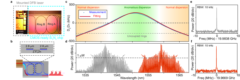
In the experiment, high- silicon nitride (SiN) coupled rings are fabricated using the CMOS-ready process 7 (Fig. 1a). The silicon nitride layer thickness is chosen as 100 nm to maintain single mode propagation while also boosting factor 7. Intrinsic factors over 100 million are achieved (Supplementary Note 1). The resonators are overcoupled with two bus waveguides (Fig. 1a,b) to enhance comb efficiency (loaded factor is million). The uncoupled resonators feature normal dispersion and will generate dark pulse combs when operated in the SIL configuration. Strong resonator coupling is introduced to lower the dispersion, creating two zero GVD wavelengths (around 1542 and 1559 nm) as shown in Fig. 1c. A discussion on repeatability of dispersion between different devices is included in Supplementary Note 5.
Coupled ring resonators 28 offer a convenient way to engineer anomalous dispersion into systems comprised of normal dispersion waveguides 29, 30. And recently they have been studied in the context of normal GVD solitons to engineer either zero-GVD 22 or controlled (as opposed to accidental 17) avoided mode crossing through hybridization of a single mode pair in a photonic molecule 31. Here, this hybridization is engineered to be broadband so as to spectrally flatten the dispersion curve and make higher-order dispersion important. This is done by first introducing strong mutual coupling of rings wherein nearly 40% of mode power is coupled between resonators, and second by close matching of the ring free-spectral range (FSR) values (the FSR difference is 100 MHz on FSRs close to 20 GHz). The factors of the coupled rings are also much higher, enabling both detectable-rate comb operation and hybrid integration with a III-V pump.
II Dispersion and SIL microcomb spectra
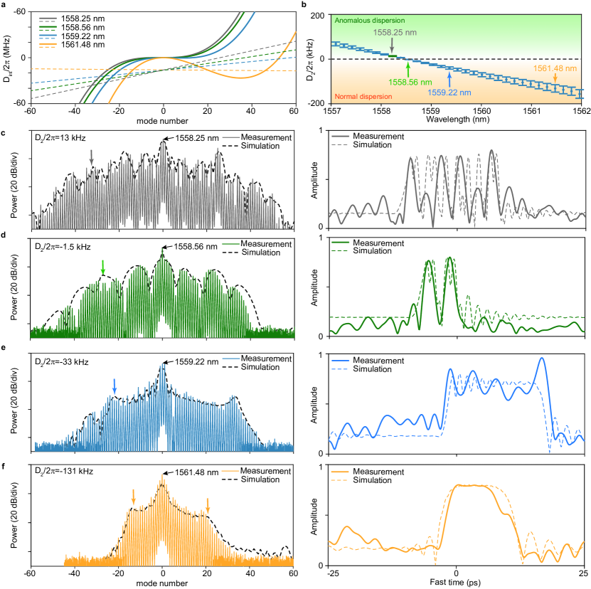
In the measurement, a DFB laser operating in the vicinity of one of the two zero-dispersion wavelengths is butt-coupled to the resonator with mW power coupled onto the waveguide (Fig. 1a,b). Rayleigh scattering inside the resonator reflects of the power into the pumping laser. An Emcore Corp. DFB laser is used for pumping near 1559 nm and a PhotonX Inc. DFB laser is used for pumping near 1541 nm. Temperature tuning of the DFB lasers allows fine tuning control of the pumping wavelength for access to slightly anomalous, near-zero, and slightly normal dispersion wavelengths of the resonator. Fig. 2a shows measurements of integrated dispersion of the resonator for pumping at specific wavelengths (provided in the legend) near 1559 nm. In the plots, corresponds to the pump line. The dispersion curves are measured using a radio-frequency calibrated interferometer reference 10.
When pumped at near-zero dispersion, the comb spectral span is strongly influenced by comb radiation into a dispersive wave, which corresponds to cavity modes that are nearly resonant with comb lines. The mode number of the dispersive wave is given as the solution to the equation 32,
| (1) |
where is the pump-laser cavity detuning as regulated by the self-injection feedback, is Kerr nonlinear coefficient, is photon number of the pumped cavity resonance, is the difference between comb repetition rate and cavity free-spectral range (), and and are second- and third-order dispersion parameters, respectively. Fig. 2b gives the measured second-order dispersion () parameter at these same pumping wavelengths, and kHz is used for all pumping wavelengths. The left side of Eqn. 1 corresponds to the frequency comb lines and is plotted as the colored dashed lines in Fig. 2a. In making these these line plots, and are numerically simulated (Supplementary Note 4). The right side of Eqn. 1 is the integrated dispersion and fitted to the experimentally measured dispersion as noted above. At each pumping wavelength, the dispersive wave mode number can be obtained as the intercept between the comb frequencies (dashed lines) and the corresponding integrated dispersion curve (solid lines).
The dispersive wave position is marked with an arrow in the left panel of Fig. 2 c-f, which show measured spectra for SIL pumping at the wavelengths in Fig. 2a. The arrow position provides a trend of measured comb span for negative mode numbers. Overall comb spectral span tends to be determined by this dispersive wave. Note that in Fig. 2, the third dispersive wave (after mode number 50) is absent in both the measured and simulated optical spectrum, which is a result of insufficient pump power. The comb spectrum in Fig. 1d spans 9.9 nm (1.22 THz) and features on-chip comb-line power higher than 1 W, marked with arrows. This comb has superior spectral coverage compared to previous SIL operated normal GVD microcombs 7, 19. It also features an increased number of comb lines compared with higher repetition rate non-bright combs directly III-V pumped with optical isolation 33. When pumped at 1541 nm near the other zero-dispersion wavelength, a microcomb spanning 9.2 nm (1.16 THz) is realized. The comb states both feature pump power conversion efficiency as high as 26% (see Supplementary Note 2). These comb spectra are plotted in Fig. 1d.
III Imaging of mode-locked microcomb states
While the temporal envelope of pulses produced by normal GVD combs has been measured using cross-correlation 17, near-zero-GVD operation allows access to a wider variety of comb states including soliton molecules (bounded bright solitons) and switching waves 34, 32. These interesting states have been analyzed numerically 35, 36, 22, but they have so far not been observed in the time domain. This is result of current zero-dispersion systems being generated with a pulsed pump where the comb waveform is influenced by the pump pulse waveform or at challenging high repetition rates 37, 23, 38. Here, the linear optical sampling technique assisted with an electro-optic frequency comb is implemented to image the temporal profile of the various comb states 27, 18. The sampling EO comb spans nm with 33 lines, corresponding to a ps pulse in the time domain, and its repetition rate is set to be slightly higher than the zero-dispersion microcomb. Note that the temporal duration of the soliton pulse (for example, 2.6 ps FWHM in Fig.2d for the left pulse in measurement) is close to the pulse width of the EO-comb ( 1.5 ps), thus the imaging result may not perfectly resolve fine structure in the temporal waveforms. By combining the EO comb and the generated comb at the “drop” port, and detecting with a fast photodetector, the sampled microcomb signal is recorded by an oscilloscope for processing.
Experimental results are presented in the right panels of Fig, 2c,d,e,f. At the anomalous side () of the near-zero GVD wavelength, the strong dispersive wave binds several solitons into soliton clusters, as observed in Fig.2c (right panel). The interference between the pulses creates the multiple fringes that are apparent in the optical spectrum (left panel). Numerically simulated time domain and spectra are also presented as dashed curves in Fig, 2c,d,e,f. The clustered soliton formation is preserved for near-vanishing GVD ( kHz) as shown in Fig, 2d, where a soliton dimer is imaged. The corresponding optical spectrum is shown in the left panel of Fig. 2d. For the pumping wavelength with normal dispersion, the resulting waveforms are often called switching waves or “platicons” 19, 18. Here, the waveform evolves towards a square pulse as the dispersion becomes more normal () (Fig. 2e-f, right panels). The present results experimentally demonstrate the evolution of comb states in the near zero GVD regime with different GVD sign, and are consistent with a previous numerical study 22.
Generally, operation of the comb with a small amount of normal dispersion (e.g. the state in Fig. 2e, pumped at 1559.2 nm) provides both good spectral coverage as well as a temporal and spectral waveform that is more regular in shape. Furthermore, the square pulse nature of these states (apparent in Fig. 2e-f, right panels) offers an increased duty cycle, which boosts comb power conversion efficiency. As a result, the microwave and optical performance of the comb state in Fig. 2e is further studied below.
IV Discipline of the comb repetition rate
Discipline of comb repetition rate to an external reference such as a clock is important in many comb applications 3. Generally, the repetition rate of microcombs is regulated by the pump-laser cavity detuning 39, 40, via channels including dispersive wave recoil 39, Raman self-frequency shift 41 and inhomogeneous back scattering 18, 42. And with laser cavity detuning controlled by the applied current on the pumping DFB laser, a fast feedback loop can be used to stabilize the microcomb’s repetition rate.
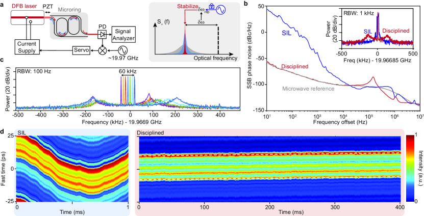
In the experiment (Fig. 3a), the microcomb’s repetition rate is detected at the resonator drop port by a fast photo detector, and analyzed by a signal analyzer (R&S FSUP). Pumping is at 1559.22 nm. The detected repetition rate tone is simultaneously split by a directional coupler after electrical amplification and mixed with a local oscillator which serves as the reference (R&S SMB 100A). The mixed-down signal is sent to a servo controller and fed back to the current supply (LDX-3620B, DC-coupled modulation response bandwidth 1 MHz) of the DFB laser to provide fine tuning control of the pump-laser cavity detuning frequency. The gap distance between the bus waveguide facet and the DFB laser head is regulated by a closed loop piezo (PZT) with a built-in strain gauge displacement sensor (Thorlabs MAX311D).
The measured phase noise of the detected repetition rate tone under open-loop and disciplined (locked) conditions is shown in Fig. 3b. The phase noise of the microwave reference is shown in gray. The phase noise of the disciplined repetition rate follows that of the microwave reference within the feedback bandwidth of approximately kHz (as defined by the offset frequency where a “bump” is observed in its frequency spectrum). The microwave spectra of the SIL and disciplined comb are plotted in inset of Fig. 3b. The repetition rate could be tuned by 60 kHz through tuning of the microwave reference (Fig. 3c). Disciplining the microcomb simultaneously stabilizes its temporal waveform. This is observable in Fig. 3d which shows round trip comb field plotted versus time. In the left panel the data are presented under unlocked conditions and show drift of the soliton waveform over a time scale of 1 ms. On the other hand, the disciplined microcomb features a measured soliton waveform that evolves very slowly and linearly (linear trend lines shown as white dashed lines). Here, the observable drift results from the difference in sampling period between the oscilloscope and EO sampling signal. All of the sampling data presented in Fig. 2 were obtained when the comb was externally disciplined.
V Comb offset frequency stabilization under repetition rate discipline
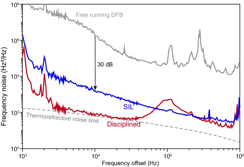
The pump laser frequency of the microcomb also determines the offset frequency of the microcomb. And self-injection locking (here of the pump laser) is known to improve frequency stability 43. In the present case, SIL stabilizes the DFB pump laser’s frequency to the high- silicon nitride cavity mode and thereby stabilizes laser-cavity detuning to a value that depends on the feedback phase and initial laser-cavity detuning without SIL feedback. The pump laser frequency noise under SIL and free-running operation is measured in Fig. 4. The measurement is performed by amplifying the microcomb output at the drop port with an erbium-dope amplifier (EDFA) and filtering out the pump line with a waveshaper. Frequency noise of the line is then measured with a cross-correlation-based self-heterodyne measurement 44 within the measurement time of 400 ms. Compared with the free running DFB laser (gray), frequency noise of the pump laser is reduced by 30 dB under SIL operation (blue) at 10 kHz offset frequency. An integrated linewidth of 7.2 kHz is obtained (). The frequency noise here is still higher than the thermal noise limit given by the dashed gray curve in Fig. 4 45 (see Supplementary Note 1).
Fluctuation of a microcomb’s repetition rate is largely controlled by the pump laser-cavity detuning 19, 42. As schematically illustrated in the inset of Fig. 3a, disciplining the microcomb’s repetition rate thus simultaneously disciplines the laser pumping frequency frequency relative to the pumped cavity resonance. With fluctuation in greatly reduced by disciplining the repetition rate, frequency noise of the pump laser frequency (and comb offset frequency) is further stabilized to the thermo-refractive noise limit, as plotted in red in Fig. 4. The bumps at 1 kHz and 2 kHz originate from the piezo-electric motor used to control the gap between the DFB laser head and the photonic chip. In principle, heterogeneous integration or butterfly packaging6 of the pump and the resonator would eliminate the need for this servo control or at least replace it with a potentially faster equivalent control. It is noted that comb offset noise at lower offset frequencies than the measurement in Fig.4 is generally possible from (but not limited to) the ambient including temperature fluctuations and mechanical vibrations, other than the noise sources noted above 46. With the same definition as above, the calculated integrated linewidth is 2.1 kHz, which is comparable to an ECDL pumped microcomb 47.
VI Summary
We have demonstrated a microwave-rate mode-locked microcomb near zero GVD using a CMOS-ready coupled ring resonators. The reduced GVD enables broader microcomb operation using integrated photonics with high conversion efficiency, while maintaining the benefits of the self-injection feedback, including turnkey operation and optical linewidth reduction. A record number of comb lines is generated for non-amplified and non-pulse-pumped operation of a normal dispersion microcomb. The dispersion engineering scheme in this paper can be extended to other wavelengths and different photonic platforms. Disciplining the microcomb to an external microwave reference simultaneously stabilizes its microwave tone, temporal waveform and optical frequency. The external discipline for the hybrid-integrated microcomb source demonstrated here can be used in a two-point optical frequency division system 26 for low-noise microwave synthesis.
References
- [1] Vahala, K. J. Optical microcavities. Nature 424, 839–846 (2003).
- [2] Kippenberg, T. J., Gaeta, A. L., Lipson, M. & Gorodetsky, M. L. Dissipative Kerr solitons in optical microresonators. Science 361 (2018).
- [3] Diddams, S. A., Vahala, K. & Udem, T. Optical frequency combs: Coherently uniting the electromagnetic spectrum. Science 369 (2020).
- [4] Chang, L., Liu, S. & Bowers, J. E. Integrated optical frequency comb technologies. Nature Photonics 16, 95–108 (2022).
- [5] Stern, B., Ji, X., Okawachi, Y., Gaeta, A. L. & Lipson, M. Battery-operated integrated frequency comb generator. Nature 562, 401 (2018).
- [6] Shen, B. et al. Integrated turnkey soliton microcombs. Nature 582, 365–369 (2020).
- [7] Jin, W. et al. Hertz-linewidth semiconductor lasers using cmos-ready ultra-high-q microresonators. Nature Photonics 15, 346–353 (2021).
- [8] Xiang, C. et al. Laser soliton microcombs heterogeneously integrated on silicon. Science 373, 99–103 (2021).
- [9] Herr, T. et al. Mode spectrum and temporal soliton formation in optical microresonators. Phys. Rev. Lett. 113, 123901 (2014).
- [10] Yi, X., Yang, Q.-F., Yang, K. Y., Suh, M.-G. & Vahala, K. Soliton frequency comb at microwave rates in a high-Q silica microresonator. Optica 2, 1078–1085 (2015).
- [11] Liang, W. et al. High spectral purity Kerr frequency comb radio frequency photonic oscillator. Nat. Commun. 6, 7957 (2015).
- [12] Suh, M.-G. & Vahala, K. Gigahertz-repetition-rate soliton microcombs. Optica 5, 65–66 (2018).
- [13] Yang, K. Y. et al. Bridging ultrahigh-Q devices and photonic circuits. Nat. Photon. 12, 297 (2018).
- [14] Liu, J. et al. Photonic microwave generation in the x-and k-band using integrated soliton microcombs. Nat. Photon. 1–6 (2020).
- [15] Kondratiev, N. et al. Self-injection locking of a laser diode to a high-Q WGM microresonator. Opt. Express 25, 28167–28178 (2017).
- [16] Pavlov, N. et al. Soliton dual frequency combs in crystalline microresonators. Opt. Lett. 42, 514–517 (2017).
- [17] Xue, X. et al. Mode-locked dark pulse Kerr combs in normal-dispersion microresonators. Nat. Photon. 9, 594–600 (2015).
- [18] Wang, H. et al. Self-regulating soliton switching waves in microresonators. Physical Review A 106, 053508 (2022).
- [19] Lihachev, G. et al. Platicon microcomb generation using laser self-injection locking. Nature communications 13, 1–9 (2022).
- [20] Fülöp, A. et al. High-order coherent communications using mode-locked dark-pulse kerr combs from microresonators. Nature communications 9, 1–8 (2018).
- [21] Xiang, C., Jin, W. & Bowers, J. E. Silicon nitride passive and active photonic integrated circuits: trends and prospects. Photonics Research 10, A82–A96 (2022).
- [22] Anderson, M. H. et al. Zero dispersion kerr solitons in optical microresonators. Nature Communications 13, 1–10 (2022).
- [23] Zhang, S., Bi, T. & Del’Haye, P. Microresonator soliton frequency combs in the zero-dispersion regime. arXiv preprint arXiv:2204.02383 (2022).
- [24] Li, Z. et al. Observations of existence and instability dynamics of near-zero-dispersion temporal kerr cavity solitons. Physical Review Research 3, 043207 (2021).
- [25] Papp, S. B. et al. Microresonator frequency comb optical clock. Optica 1, 10–14 (2014).
- [26] Li, J., Yi, X., Lee, H., Diddams, S. A. & Vahala, K. J. Electro-optical frequency division and stable microwave synthesis. Science 345, 309–313 (2014).
- [27] Yi, X., Yang, Q.-F., Yang, K. Y. & Vahala, K. Imaging soliton dynamics in optical microcavities. Nature communications 9, 1–8 (2018).
- [28] Boeck, R., Jaeger, N. A., Rouger, N. & Chrostowski, L. Series-coupled silicon racetrack resonators and the vernier effect: theory and measurement. Optics express 18, 25151–25157 (2010).
- [29] Soltani, M., Matsko, A. & Maleki, L. Enabling arbitrary wavelength frequency combs on chip. Laser & Photonics Reviews 10, 158–162 (2016).
- [30] Kim, S. et al. Dispersion engineering and frequency comb generation in thin silicon nitride concentric microresonators. Nature communications 8, 1–8 (2017).
- [31] Helgason, Ó. B. et al. Dissipative solitons in photonic molecules. Nature Photonics 15, 305–310 (2021).
- [32] Li, Z., Xu, Y., Coen, S., Murdoch, S. G. & Erkintalo, M. Experimental observations of bright dissipative cavity solitons and their collapsed snaking in a kerr resonator with normal dispersion driving. Optica 7, 1195–1203 (2020).
- [33] Shu, H. et al. Sub-milliwatt, widely-tunable coherent microcomb generation with feedback-free operation. arXiv preprint arXiv:2112.08904 (2021).
- [34] Garbin, B. et al. Experimental and numerical investigations of switching wave dynamics in a normally dispersive fibre ring resonator. The European Physical Journal D 71, 1–8 (2017).
- [35] Parra-Rivas, P., Gomila, D., Leo, F., Coen, S. & Gelens, L. Third-order chromatic dispersion stabilizes kerr frequency combs. Optics letters 39, 2971–2974 (2014).
- [36] Parra-Rivas, P., Gomila, D. & Gelens, L. Coexistence of stable dark-and bright-soliton kerr combs in normal-dispersion resonators. Physical Review A 95, 053863 (2017).
- [37] Anderson, M. H., Leo, F., Erkintalo, M. J., Coen, S. & Murdoch, S. G. Measurement of the raman self-frequency shift of a temporal cavity soliton. In Nonlinear Photonics, NW4A–4 (Optical Society of America, 2016).
- [38] Xiao, Z. et al. Zero-dispersion soliton generation in a high-q fiber fabry-pérot microresonator. In CLEO: Science and Innovations, SW2H–6 (Optica Publishing Group, 2021).
- [39] Yi, X. et al. Single-mode dispersive waves and soliton microcomb dynamics. Nat. Commun. 8, 1–9 (2017).
- [40] Lucas, E. et al. Ultralow-noise photonic microwave synthesis using a soliton microcomb-based transfer oscillator. Nat. Commun. 11, 1–8 (2020).
- [41] Yi, X., Yang, Q.-F., Yang, K. Y. & Vahala, K. Theory and measurement of the soliton self-frequency shift and efficiency in optical microcavities. Opt. Lett. 41, 3419–3422 (2016).
- [42] Kondratiev, N. M. et al. Numerical study of solitonic pulse generation in the self-injection locking regime at normal and anomalous group velocity dispersion. Optics Express 28, 38892–38906 (2020).
- [43] Liang, W. et al. Whispering-gallery-mode-resonator-based ultranarrow linewidth external-cavity semiconductor laser. Optics letters 35, 2822–2824 (2010).
- [44] Yuan, Z. et al. Correlated self-heterodyne method for ultra-low-noise laser linewidth measurements. Optics Express 30, 25147–25161 (2022).
- [45] Kondratiev, N. & Gorodetsky, M. Thermorefractive noise in whispering gallery mode microresonators: Analytical results and numerical simulation. Phys. Lett. A 382, 2265–2268 (2018).
- [46] Newbury, N. R. & Swann, W. C. Low-noise fiber-laser frequency combs. JOSA B 24, 1756–1770 (2007).
- [47] Lei, F. et al. Optical linewidth of soliton microcombs. Nature Communications 13, 1–9 (2022).
Funding. Defense Advanced Research Project Agency GRYPHON (HR0011-22-2-0009) and APHI (FA9453-19-C-0029) programs; NASA.
Acknowledgments. The authors thank H. Blauvelt at EMCORE Corporation for supplying the DFB laser used in this study, as well as N. Kondratiev and V. Lobanov for discussions on numerical modelings. The authors also thank S. Diddams and F. Quinlan for fruitful comments on the results. The reported here research performed by W. Z., V.S.I. and A.B.M. was carried out at the Jet Propulsion Laboratory, California Institute of Technology, under a contract with the National Aeronautics and Space Administration (80NM0018D0004).
Disclosures. The authors declare no conflicts of interest.