Parallel Multi-Extended State Observers based ADRC with Application to High-Speed Precision Motion Stage
Abstract
In this paper, the parallel multi-extended state observers (ESOs) based active disturbance rejection control approach is proposed to achieve desired tracking performance by automatically selecting the estimation values leading to the least tracking error. First, the relationship between the estimation error of ESO and the tracking error of output is quantitatively studied for single ESO with general order. In particular, the algorithm for calculating the tracking error caused by single ESO’s estimation error is constructed. Moreover, by timely evaluating the least tracking error caused by different ESOs, a novel switching ADRC approach with parallel multi-ESOs is proposed. In addition, the stability of the algorithm is rigorously proved. Furthermore, the proposed ADRC is applied to the high-speed precision motion stage which has large nonlinear uncertainties and elastic deformation disturbances near the dead zone of friction. The experimental results show that the parallel multi-ESOs based ADRC has higher tracking performance than the traditional single ESO based ADRC.
Index Terms:
extended state observer, active disturbance rejection control, high-order LESO, HSPMS, switching controller.I Introduction
Uncertainties, including unmodeled dynamics, time-varying parameters and external disturbances, widely exist in various industrial control systems. How to force the system to track the desired output signal under the influence of uncertainties is a basic problem throughout the development of control science. To cover the uncertainties in system dynamics, a number of control methods were presented, such as proportional-integral-derivative (PID) control [1], adaptive control [2], sliding mode control [3], disturbance observer basic control (DOBC) [4] and active disturbance rejection control (ADRC) [5, 6]. Among them, since ADRC can estimate and compensate the “total disturbance” including internal uncertain dynamics and external disturbances in real time through its core module extended state observer (ESO), it has received wide attention. Apart from theoretical studies about the stability and convergence of ADRC [7, 8], a significant increase in applications of ADRC across different fields can be noticed in recent years, including but not limited to spacecraft control systems [9, 10, 11], power electronics [12, 13], motion control systems [14, 15, 16, 17] and others [18, 19].
Since the key idea of ADRC is timely estimating both states and total disturbance, how to improve ESO to achieve better estimation is an important topic. One kind of representative work is to improve the observation accuracy of ESO by designing time-varying observer gains: [20] proposed the adaptive ESO (AESO) based ADRC, in which the gain of ESO was timely tuned to reduce the estimation errors of both states and the “total disturbance” against the measurement noise, and applied it to the air-fuel ratio (AFR) control of gasoline engine. [21] designed ESO with predetermined decreasing gains to reduce the influence of measurement noise in system steady state and the method was tested in a magnetic levitation ball system. [22] proposed an adaptive ADRC parameters adjustment algorithm based on off-line Q-learning and applied it to the ship course control. Moreover, there were analogous attempts in [23, 24].
In addition to studying the most typical ESO, which is usually one order higher than the system order, some scholars have also focused their attention on high-order ESO, which can estimate the high-order derivative of the total disturbance. By analyzing and comparing the frequency regional performance of different order ESOs, [16] drew the conclusion that as the order of ESO increased, its disturbance rejection ability also increased, but the estimation performance also became more sensitive to noise. [18], [25] and [26] studied the stability of high-order ESOs in time-domain and pointed out the influence of each parameter on ESO and the closed-loop system.
Moreove, the structure of ESO has also been extensively studied. The most typical examples are the non-linear ESO (NLESO) and the linear ESO (LESO) [5]. [27] proposed a linear/non-linear switching extended state observer (L/NL-SESO) to solve the problem that NLESO was limited to large amplitude disturbance estimation and the performance of the corresponding ADRC algorithm was improved indirectly. Aiming to reduce the impact of measurement noise on ESO, [28] proposed the cascade ESO (CESO) in which a unique cascade combination of ESOs was developed and the estimation of the “ total disturbance” was the sum of the ESOs’ estimations. [29] studied the time-domain responses of the 3rd-order LESO and the 4th-order LESO to step disturbance and proposed a switching ADRC based on parallel 3rd-order LESO and 4th-order LESO. As for the defects of traditional ESO in estimating large scale fast-varying sinusoidal disturbance (FVSD), [30] came up with the generalized integrator-extended state observer (GI-ESO), which enabled FVSD to be observed with a relatively low bandwidth, and applied it to the Grid-connected Converters.
However, as mentioned above, almost all of these improvements indirectly improved the control effect of ADRC by improving the estimation ability of ESO, rather than directly optimizing the control law. Along this line, two problems arise: How does the estimation effect of ESO affect the control performance of ADRC, in other words, does a smaller estimation error mean a smaller tracking error? If the answer is negative, then how to optimize the control law directly?
In this paper, we explore the above two questions and propose the parallel multi-ESOs based ADRC design approach. Our contribution can be summed up as follows:
(i) The relationship between the estimation error of ESO and the tracking error of controlled output is quantitatively studied for single ESO with general order. In particular, the algorithm for calculating the deviation of tracking caused by ESO’s estimation error is proposed.
(ii) By timely evaluating the least tracking error caused by different ESOs, a novel switching ADRC approach with parallel multi-ESOs is proposed. Furthermore, the stability of the algorithm is rigorously proved under some standard assumptions.
(iii) The proposed control scheme is implemented in a high-speed precision motion stage for higher precision of tracking.. The experimental results show the validity and strong robustness of our method, with the parallel multi-ESOs based ADRC has higher control performance.
The rest of this paper is arranged as follows: Section II presents the basic problem formulation to study. Section III analyzes the influence of the estimation error of LESO on the control performance and gives the designing approach of the parallel multi-ESOs based ADRC. Experimental studies are shown in Section IV and some conclusions are given in Section V.
II Problem Formulation
Considering the following SISO system combined with uncertain dynamics and external disturbances:
| (1) |
where
| (2) |
is time, is the state vector, and are the input and output of the system, respectively. is the known input gain. represents internal uncertain dynamics and external disturbances.
This paper considers the control problem in which a signal is taken as the reference command for the system output In practice, the output is usually expected to track the desired reference signal despite various uncertainties. Usually, is requested to achieve desired both transient and steady performances which can be described by the following ideal trajectory:
| (3) |
, , and the matrix is a Hurwitz matrix whose characteristic polynomial has following form:
| (4) |
where , and . Apparently, the performance of can be optimized by tuning .
In this paper, we focus on the following control objective:
| (5) |
where is the maximum acceptable tracking error between and its ideal trajectory .
Defining and , we have . Therefore, the control objective (5) can be equivalent to the tracking problem of to :
| (6) |
Now, the problem is how to design control law to achieve control object (6). First, according to (1) and (3), the ideal closed-loop error system could be written as :
| (7) |
Then, we rewrite (1) in terms of the tracking error :
| (9) |
However, it is difficult to obtain the high-order differential of the reference signal and the system states can not be measured, which both lead to that each differential of the tracking error can’t be obtained. Besides that, the total disturbance is also unknown. Despite these difficulties, we could estimate and in real time by designing the LESO and design ADRC law to achieve the control object.
III Parallel Multi-ESOs based ADRC Design
III-A Single LESO based ADRC Design
In this section, a -th order LESO based ADRC is designed to reach the control object. It is worth noting that the following study always holds for ADRC based on th order LESO, .
Generally, a th order LESO has the following form :
| (10) |
where is the estimation of ,
| (11) |
and
| (12) |
The observer bandwidth is the parameter to be adjusted and is the estimation value of , where .
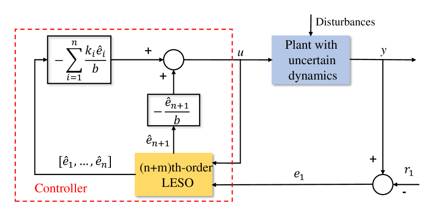
Then, the following traditional signal ESO based ADRC law could be designed as (13)
| (13) |
and the error system between (7) and (8) could be described as (14) :
| (14) |
where , and .
The control block diagram is shown in Fig. 1.
For the convenience of subsequent analysis, we redefine the tracking error vector . Let be the estimation error vector, then the dynamic of LESO’s estimation error could be described as follow:
| (15) |
where .
Actually, to guarantee the stability of ADRC, it is essential to prove the boundedness of the LESO’s estimation error.
In fact, the stability of the designed -th order LESO has been well studied in [25] under the following Assumptions 1-2:
Assumption 1. There is a positive integer such that the first th derivatives of are bounded, i.e., there exists such that
| (20) |
Assumption 2. The exists a known positive satisfying
| (21) |
Here, we quote their conclusion as Lemma 1 directly.
III-B Parallel Multi-ESOs based ADRC Design
In order to give full play to the advantages of LESOs with different orders and parameters, a natural idea is to set parallel multi-LESOs and choose different LESO based ADRC laws according to the real time data. Therefore, it is necessary to analyze how the different orders and parameters of LESO will affect the control effect.
In the rest of this article, we use and to represent the Laplace transform and inverse Laplace transform, respectively. Lemma 2 below describes the influence of LESO’s estimation error on the control error quantitatively.
Lemma 2. Considering the estimation error systems (15) and the closed-loop error system (14) under the same condition of Lemma 1, the tracking error satisfies the following formula:
| (24) |
where
| (25) |
and
| (26) |
Remark 1. Lemma 2 demonstrates the relation between and , as well as the initial values. In addition, we will prove the boundedness of and later, which guarantees the existence of the Laplace transform.
Proof of Lemma 2.
Just considering the first equations of (15) and taking Laplace transform to them, then we have:
| (27) |
After sorting it out, can be expressed by and the initial estimation error of each state:
| (28) |
In the same way, taking Laplace transform to (14) and then we have
| (29) |
After sorting out the above equations, expressed by and the initial estimation error of each state is obtained:
| (30) |
Taking Inverse Laplace transform to (30), the result is obtained.
However, by (24), it needs to know the unmeasurable to compute . Ignoring the influences of these initial values, an approximation of can be indicated as
| (31) |
Although there is an approximate error, the following Theorem 1 demonstrates that will converge to as time goes on.
Theorem 1. Considering the calculation formula (24) of tracking error and its approximation formula (31), there are
(i)
| (32) |
where
| (33) |
(ii)
| (34) |
Remark 2. Theorem 2 illustrates that will converge to the true value over time, and the convergence speed can be accelerated by rational pole allocation. Thus, can be calculated approximately by only using the available .
Proof of Theorem 1.
Decomposing and the following result could be obtained:
| (35) |
where
| (36) |
Using the residue theorem, it can be computed :
| (37) |
As a result, it is easy to see that
| (38) |
Then we have
| (39) | ||||
Obviously, holds.
Along with the above ideas, this paper chooses as the control indicator to evaluate the tracking performance of different control laws. A subsequent problem is that we can only measure the tracking error caused by the selected control law, but how should those control laws that were not selected be evaluated? Lemma 2 and Theorem 1 give an answer: the tracking error can be figured out by only using . Therefore, by comparing caused by different control laws, we could choose the one which minimizes it.
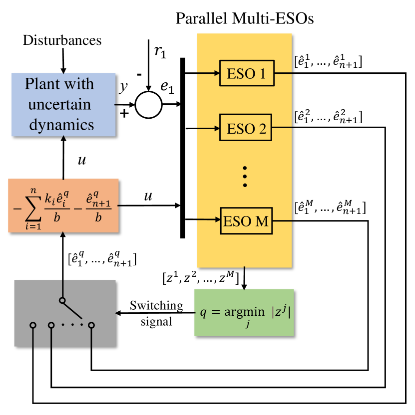
In the following work, we propose an novel ADRC design approach, which is based on simultaneous LESOs with different orders and bandwidths. With as the optimal indicator, the proposed algorithm is shown in Algorithm 1, in which is the estimation of the th LESO with respect to . Moreover, the control block diagram is shown in Fig. 2.
III-C Stability Analysis for Parallel Multi-ESOs based ADRC
This section is going to analyse the closed-loop stability of the proposed parallel multi-LESOs based ADRC.
After ensuring the stability of the LESOs, we have the following Theorem 2 to guarantee the boundedness of tracking error.
Theorem 2. Considering the closed-loop error system (14) and the parallel multi-LESOs based ADRC algorithm under the same conditions as Lemma 1, we have the following results for any :
| (40) |
Remark 3. Obviously, the first item of the right hand of (40) converges to 0 as . For the second item, noting that only depends on the estimation errors, it can be known that although the estimation errors of M LESOs are different, as long as their boundedness can be guaranteed, the parallel multi-ESOs based ADRC would be able to achieve the control goal under rational pole allocation.
Proof of Theorem 2.
The explicit solution of (14) is
| (41) |
On the one hand,
| (42) | ||||
On the other hand, it is easy to verify that
| (43) |
In addition, it can be seen from matrix function theory that
| (44) |
Thus,
| (45) | ||||
Then it holds
| (46) |
Therefore, we have
| (47) |
where and
| (48) |
can be derived directly
| (49) | ||||
where “*” are unknown items we do not care. Then it can be obtained
| (50) |
Let and then
| (51) |
Now we are going to study the properties of . Calculating directly, we have
| (52) |
Obviously, the right hand of the equation is monotonically increasing to on . Thus,
| (53) |
where
| (54) |
Finally,
| (55) |
IV Application to High-Speed Precision Motion Stage
As the core module of intelligent manufacturing, high speed precision motion stage (HSPMS) is widely used in integrated circuit manufacturing, microelectronics processing technology, semiconductor processing industry [31, 32, 33]. Due to the high-stiffness structure, traditional high-speed precision motion stage (HSPMS) is affected by high frequency disturbance near the dead zone of friction. The friction is a very complex non-linear phenomenon which can cause large steady-state error and oscillation. In order to overcome this shortcoming, [34] designed the rigid-flexible coupling (RFC) stage, which can convert high-frequency friction disturbance into low-frequency friction disturbance through special structural design. Moreover, it proved that the traditional LESO based ADRC can estimate and compensate low frequency disturbances effectively. In the following researches, the parallel multi-ESOs based ADRC will be verified in the RFC stage.
IV-A Experimental Setup and Dynamical Model
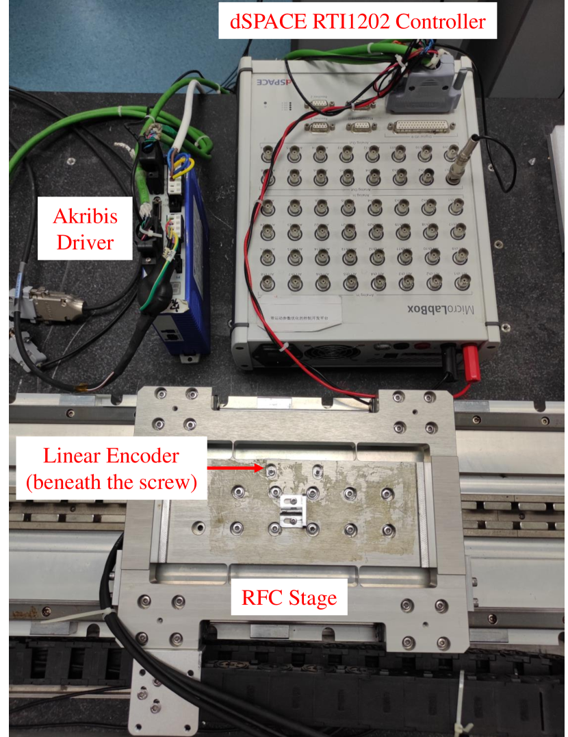
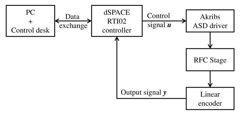
The chosen experimental equipment is the RFC stage motion control system shown in Fig. 3, which consists of dSPACE RTI1202 controller, Akribs ASD driver, Renishw incremental linear encoder (0.1 m resolution) and the RFC stage. The workflow of this equipment is shown in Figure 1.
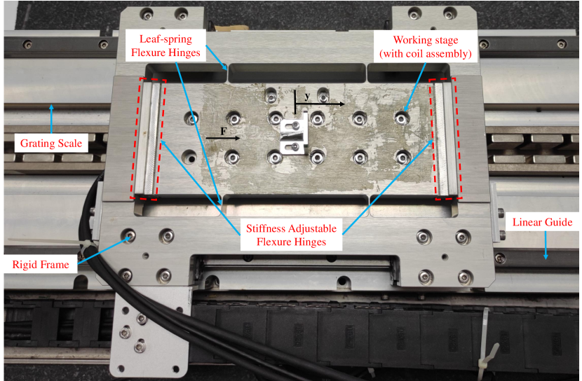
As shown in Fig. 5, the RFC stage consists of two parts: a working stage and a rigid frame, which are connected by flexible hinges. When the rigid frame is in the friction dead zone, the displacement of the working stage is realized by the elastic deformation of the flexure hinge. The working stage, the leaf spring flexure hinge and the rigid frame are machined in one piece, made from aero duralumin 7075 to eliminate assembly errors. The flexible hinges with adjustable stiffness are made of 65mn spring steel. After assembly, the table and rigid frame are connected together from both ends to ensure fatigue life. Besides that, the linear encoder and coil assembly are installed on the working stage to measure the displacement output and receive the control input . The rigid frame is installed on the linear guide rail to achieve large stroke movement.
The equivalent mechanics model of the RFC positioning stage is shown in Fig. 6. We can see that the flexure hinges keep the working stage free from friction and only rigid frame is affected by friction.
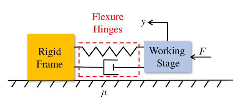
Since the input and output of the system are all on the working stage, the following study only takes the working stage as the plant for simplicity. All the effects caused by the rigid frame are applied to the working stage as disturbance of flexure hinge. Hence, the dynamic model of the RFC positioning stage can be described as
| (56) |
The physical meanings of each symbol are shown in TABLE I.
| Symbol | Physical Meaning |
|---|---|
| Displacement of the working stage | |
| Velocity of the working stage | |
| Proportion from voltage to current | |
| Force constant of linear motor | |
| Mass of the working stage | |
| Analog voltage | |
| Equivalent stiffness of flexure hinges | |
| Equivalent damping of flexure hinges | |
| Flexure hinges’ elastic deformation | |
| Flexure hinges’ elastic deformation rate | |
| Uncertainty and disturbance | |
| Measurement output |
IV-B Experiment of Point-to-Point Motion
In the field of electronics manufacturing and laser processing industry, high precision is the biggest characteristic of point-to-point motion. Therefore, in the following experiment, we consider the displacement control of the working stage, that is, let track the command signal .
The ideal closed-loop system is set as (3) with , and . Taking as the “total disturbance”, the following 3rd-order LESO (57) and 4th-order LESO (58) with are set to estimate , and . Besides that, the input gain is 3.25.
| (57) |
| (58) |
Correspondingly, the approximate formula (31) can be written as
| (59) |
for . However, due to the influence of measurement noise, there may be errors in the calculation of , which may cause frequent switches between the two ESOs and result in frequent and drastic changes in the input. To overcome this problem, in the actual experiment, the switching judgment is executed every 20 sampling periods and the switching index is changed to the cumulative value of accordingly.
To verify the proposed parallel multi-ESOs based ADRC method, the above LESOs are run at the same time. In addition, the respective traditional ADRC based on these 2 LESOs are set as comparisons.
IV-C Experimental Results
Fig. 7 shows the tracking errors of different control laws when is taken as the reference signal. Compared with the ADRC based on 3rd-order LESO, the proposed method has a smaller tracking error in the initial stage and enters the steady state faster. Compared with the ADRC based on 4th-order LESO, the proposed method has a smoother error curve, which means that the system output is smoother. Besides that, the IAE of the above three methods are shown in Table II.
| Control law | IAE |
|---|---|
| ADRC based on 3rd-order LESO | 105.95 |
| ADRC based on 4th-order LESO | 86.15 |
| Parallel Multi-ESOs based ADRC | 82.67 |
Fig. 8 shows the curves of input and switching signal, where switching signal “0” represents the 3rd-order LESO and “1” represents the 4th-order LESO. As can be seen from the figure, when the control law switches between the two LESOs, there will be a small fluctuation in the system input. The maximum fluctuation occurs at t=0.2s and the voltage changes from -1.1V to 0.6V. Considering that the set voltage variation range is -1010V, the variation of 1.7V is acceptable. Moreover, combined with Fig. 7 and Fig. 8, it can be seen that the sudden change of input has no significant influence on the closed-loop system.
Considering the difference of friction disturbance in different parts of mechanical bearing and the randomness near the friction dead zone, it is necessary to make repeated experiment with different trajectories. Fig. 9 demonstrates the tracking error curves under and , respectively, each repeated 5 times. On the one hand, the dynamic characteristics of tracing error curves are very similar for different reference signals. On the other hand, the error curves are almost the same for 5 repeated experiments for the same reference signal. All these results show the robustness of the parallel multi-ESOs based ADRC. Furthermore, we also conducted 5 repeated experiments on the two control groups, and their mean IAEs are shown in Table III.
| ADRC based on 3rd-order LESO | 101.29 | 176.46 |
| ADRC based on 4th-order LESO | 86.00 | 170.34 |
| Parallel Multi-ESOs based ADRC | 82.18 | 164.78 |
V Conclusion
From the obtained results, one can see that the estimation error of ESO and the tracking error of ADRC are not exactly positively correlated, which suggests that in order to improve the control performance of ADRC, it is not enough to only consider optimization of ESO. Therefore, this paper directly starts from the control effect, by setting up parallel ESOs to switch different control laws online, so as to achieve an improvement on the traditional ADRC. The stability and superiority of the method are proved by theory and experimental results.
Acknowledgments
This work is supported by the National Natural Science Foundation of China under Grant U20A6004, 51875108 and National Key R&D Program of China ( 2022YFB4701001).
References
- [1] H. Wu, W. Su, and Z. Liu, “Pid controllers: Design and tuning methods,” in 2014 9th IEEE Conference on Industrial Electronics and Applications, 2014, pp. 808–813.
- [2] M. Bodson, Adaptive Control: Stability, Convergence, and Robustness. Prentice Hall, 2011.
- [3] C. Edwards and S. K. Spurgeon, Sliding Mode Control: Theory And Applications. Crc Press, 1998.
- [4] S. Li, J. Yang, W. H. Chen, and X. Chen, Disturbance Observer-Based Control: Methods and Applications. CRC press, 2014.
- [5] J. Han, “From PID to Active Disturbance Rejection Control,” IEEE Transactions on Industrial Electronics, vol. 56, no. 3, pp. 900–906, 2009.
- [6] Z. Gao, “Active disturbance rejection control: a paradigm shift in feedback control system design,” in American Control Conference, 2006.
- [7] W. Xue and Y. Huang, “On performance analysis of ADRC for nonlinear uncertain systems with unknown dynamics and discontinuous disturbances,” in Proceedings of the 32nd Chinese Control Conference, 2013, pp. 1102–1107.
- [8] B. Z. Guo and Z. L. Zhao, “On the convergence of an extended state observer for nonlinear systems with uncertainty,” Systems & Control Letters, vol. 60, no. 6, pp. 420–430, 2011.
- [9] Y. Xia, Z. Zhu, M. Fu, and S. Wang, “Attitude tracking of rigid spacecraft with bounded disturbances,” IEEE Transactions on Industrial Electronics, vol. 58, no. 2, pp. 647–659, 2011.
- [10] M. Sun, Z. Chen, and Z. Yuan, “A practical solution to some problems in flight control,” in IEEE Conference on Decision & Control, 2009, pp. 1482–1487.
- [11] H. Yang, L. Cheng, Y. Xia, and Y. Yuan, “Active disturbance rejection attitude control for a dual closed-loop quadrotor under gust wind,” IEEE Transactions on Control Systems Technology, vol. 26, no. 4, pp. 1400–1405, 2018.
- [12] B. Sun and Z. Gao, “A dsp-based active disturbance rejection control design for a 1-kW H-bridge DC-DC power converter,” IEEE Transactions on Industrial Electronics, vol. 52, no. 5, pp. 1271–1277, 2005.
- [13] R. Xu, Y. Yu, R. Yang, G. Wang, D. Xu, B. Li, and S. Sui, “A novel control method for transformerless H-Bridge cascaded statcom with star configuration,” IEEE Transactions on Power Electronics, vol. 30, no. 3, pp. 1189–1202, 2015.
- [14] H. Sira-Ramirez, J. Linares-Flores, C. Garcia-Rodriguez, and M. A. Contreras-Ordaz, “On the control of the permanent magnet synchronous motor: An active disturbance rejection control approach,” IEEE Transactions on Control Systems Technology, vol. 22, no. 5, pp. 2056–2063, 2014.
- [15] J. Linares-Flores, J. L. Barahona-Avalos, H. Sira-Ramirez, and M. A. Contreras-Ordaz, “Robust passivity-based control of a Buck-Boost-Converter/DC-Motor system: An active disturbance rejection approach,” IEEE Transactions on Industry Applications, vol. 48, no. 6, pp. 2362–2371, 2013.
- [16] J. Li, H. Ren, and Y. Zhong, “Robust speed control of induction motor drives using first-order auto-disturbance rejection controllers,” IEEE Transactions on Industry Applications, vol. 51, no. 1, pp. 712–720, 2015.
- [17] A. Castañeda, L.and Luviano-Juárez and I. Chairez, “Robust trajectory tracking of a delta robot through adaptive active disturbance rejection control,” IEEE Transactions on Control Systems Technology, vol. 23, no. 4, pp. 1387–1398, 2015.
- [18] L. Shao, X. Liao, Y. Zhang, and Q. Deng, “Application of active disturbance rejection controller and extend state observer for pmsm,” Transactions of China Electrotechnical Society, vol. 21, no. 6, pp. 35–39, 2006.
- [19] Z. Su, Y. Sun, X. Zhu, Z. Chen, and L. Sun, “Robust tuning of active disturbance rejection controller for time-delay systems with application to a factual electrostatic precipitator,” IEEE Transactions on Control Systems Technology, vol. 30, no. 5, pp. 2204–2211, 2022.
- [20] W. Xue, W. Bai, S. Yang, K. Song, Y. Huang, and H. Xie, “Adrc with adaptive extended state observer and its application to air-fuel ratio control in gasoline engines,” IEEE Transactions on Industrial Electronics, vol. 62, no. 9, pp. 5847–5857, 2015.
- [21] W. Wei, W. Xue, and D. Li, “On disturbance rejection in magnetic levitation,” Control Engineering Practice, vol. 82, pp. 24–35, 2019.
- [22] Z. Chen, B. Qin, M. Sun, and Q. Sun, “Q-learning-based parameters adaptive algorithm for active disturbance rejection control and its application to ship course control,” Neurocomputing, vol. 408, pp. 51–63, 2020.
- [23] C. Liu, G. Luo, X. Duan, Z. Chen, and C. Qiu, “Adaptive LADRC-based disturbance rejection method for electro-mechanical servo system,” IEEE Transactions on Industry Applications, vol. PP, no. 99, pp. 1–1, 2019.
- [24] Z. Pu, R. Yuan, J. Yi, and X. Tan, “A class of adaptive extended state observers for nonlinear disturbed systems,” IEEE Transactions on Industrial Electronics, vol. 62, no. 9, pp. 5858–5869, 2015.
- [25] J. Shi, X. Chen, and S. Yau, “High order linear extended state observer and error analysis of active disturbance rejection control,” Asian Journal of Mathematics, vol. 23, no. 4, pp. 631–650, 2019.
- [26] A. Luviano-Juarez, J. Cortes-Romero, and H. Sira-Ramirez, “Synchronization of chaotic oscillators by means of generalized proportional integral observers,” International Journal of Bifurcation and Chaos, vol. 20, no. 05, pp. 1509–1517, 2010.
- [27] Z. X. Chen, Q. H. Gao, and T. N. Department, “Linear/nonlinear switching extended state observer,” Control Theory & Applications, vol. 36, no. 6, pp. 902–908, 2019.
- [28] A. Ka and B. Rm, “Cascade extended state observer for active disturbance rejection control applications under measurement noise,” ISA Transactions, vol. 109, pp. 1–10, 2021.
- [29] G. Tang, W. Xue, and Z. Jiang, “Two parallel extended state observers based switching adrc design for a class of motion control systems,” in 2022 41st Chinese Control Conference (CCC), 2022, pp. 265–270.
- [30] B. Guo, S. Bacha, M. Alamir, A. Hably, and C. Boudinet, “Generalized integrator-extended state observer with applications to grid-connected converters in the presence of disturbances,” IEEE Transactions on Control Systems Technology, vol. 29, no. 2, pp. 744–755, 2021.
- [31] Y. Yazaki, H. Fujimoto, K. Sakata, A. Hara, and K. Saiki, “Settling time shortening method using final state control for high-precision stage with decouplable structure of fine and coarse parts,” in IECON 2014 - 40th Annual Conference of the IEEE Industrial Electronics Society, 2014, pp. 2859–2865.
- [32] H. Y., Y. W., G. J., C. C., C. X., C. X., Y. Z., Z. K., C. Y., and Z. Y., “Research on dual-linear motor synchronous control in the high-precision gantry motion platform,” in 2017 IEEE 19th Electronics Packaging Technology Conference (EPTC), 2017, pp. 1–5.
- [33] K. Saiki, A. Hara, K. Sakata, and H. Fujimoto, “A study on high-speed and high-precision tracking control of large-scale stage using perfect tracking control method based on multirate feedforward control,” IEEE Transactions on Industrial Electronics, vol. 57, no. 4, pp. 1393–1400, 2010.
- [34] H. Peng, Z. Yang, W. Xue, R. Huang, and Y. Huang, “The design and control of a rigid-flexible coupling positioning stage for enhanced settling performance,” Journal of Dynamic Systems, Measurement, and Control, vol. 143, no. 11, 2021.