Rapid quantum approaches for combinatorial optimisation inspired by optimal state-transfer
Abstract
We propose a new design heuristic to tackle combinatorial optimisation problems, inspired by Hamiltonians for optimal state-transfer. The result is a rapid approximate optimisation algorithm. We provide numerical evidence of the success of this new design heuristic. We find this approach results in a better approximation ratio than the Quantum Approximate Optimisation Algorithm at lowest depth for the majority of problem instances considered, while utilising comparable resources. This opens the door to investigating new approaches for tackling combinatorial optimisation problems, distinct from adiabatic-influenced approaches.
1 Introduction
In a combinatorial optimisation problem, such as MAX-CUT or the TRAVELLING-SALESPERSON [1], the aim is to evolve from some initial state to a final state that encodes the solution to the optimisation problem. One approach might be to evolve adiabatically, encoding each of the initial and final states as the ground state of some Hamiltonian and interpolating sufficiently slowly between them. In practice this approach is limited by the minimum spectral gap of the interpolating Hamiltonian [2, 3]. This approach is known as adiabatic quantum optimisation (AQO) [4, 5, 6, 7, 8].
In the absence of mature hardware, AQO has relied on the adiabatic principle as a guiding design tenet. In turn AQO has lead to Quantum Annealing (QA). Similar to AQO, QA attempts to interpolate continuously between the initial and final Hamiltonians. QA denotes a broader approach than AQO to find (or approximate) the solution of the optimisation problem. This could include: thermal effects [9]; intentionally operating diabatically [10, 11, 12]; or adding new terms to the Hamiltonian [13, 14, 15, 16, 17, 18]. QA has gone on to help inspire a number of other approaches, such as: the gate-based Quantum Approximate Optimisation Algorithm (QAOA) [19]; continuous-time quantum walks (QW) for optimisation [20, 21]; and combinations of different approaches [22, 23]. In short, the adiabatic principle has been a successful design-principle for developing new heuristic quantum algorithms for optimisation.
An alternative approach for evolving from an initial state to the final state might be via Hamiltonians for optimal state transfer [24]. These are Hamiltonians that transfer the system from the initial state to the final state in the shortest possible time. In this paper we use these Hamiltonians as our underlying design principle. Such Hamiltonians typically require knowledge of the final state (i.e., the solution to the optimisation problem). In the absence of this information we therefore focus on how the behaviour of these Hamiltonians might be approximated to find approximate solutions to optimisation problems. The result is a rapid continuous-time approach, with a single variational parameter.
The framework of this paper is as follows: Sections 2, 3, and 4 introduce the requisite background material and introduce the Hamiltonians considered in the rest of the paper (Sec. 3). Sections 5, 6, and 7 provide analytical and numerical evidence for the performance of these Hamiltonians. Throughout the paper we adopt the convention . The corresponding Pauli matrices are denoted by and . The identity is denoted by . The commutator is denoted by . The simulations make use of the Python packages QuTiP [25, 26] and Qiskit [27]. Details about the numerical studies, including discussion about the presentation of numerical results can be found in Appendix D.
2 The QA-framework
Before elaborating on our new approach, in this section we provide a very brief overview of the adiabatic influenced algorithms mentioned in the introduction.
In QA, typically the optimisation problem is encoded as finding the ground-state, , of an Ising Hamiltonian, . The system is initialised in the ground-state, , of an easy to prepare Hamiltonian . Usually, is taken to be the transverse-field Hamiltonian. The optimisation problem is solved by evolving the system to the ground-state of . We refer to this set-up as the QA-framework. We utilise this encoding of the optimisation problem for our new approach.
For the adiabatic influenced approaches (AQO, QA, QAOA and QW) the system is subjected to the following Hamiltonian:
| (1) |
where denotes time. The design philosophy behind how the schedules and are chosen, is what distinguishes these near-term intermediate-scale quantum (NISQ) [28] approaches. For AQO, the schedules are chosen to interpolate adiabatically between the two ground states [4, 5, 6, 7]. In QA, this restriction is loosened to typically continuous, monotonically decreasing for and increasing for , schedules [10, 29]. In QW and are taken to be constants over the whole evolution [20, 21].
QAOA [19] is a gate-based design-philosophy for determining the schedules. In QAOA either and , or and . The switching parameter, , controls the number of times the schedules alternate between the two parameter settings. The duration between switching is either determined prior to the evolution by a classical computer or by using a classical variational outer-loop attempting to minimise by varying free-parameters. QAOA again relies on the adiabatic principle to provide a guarantee of finding the ground-state in the limit of infinite . However, far from this limit, the variational method allows QAOA to exploit non-adiabatic evolution [30]. QAOA has been further generalised, retaining its switching framework to the ‘Quantum Alternating Operator Ansatz’ [31]. It has also become a popular choice for benchmarking the performance of quantum hardware [32, 33, 34].
Recently Brady et al. applied optimal control-theory to help design and investigate schedules [35, 36, 37]. They demonstrated for and , that the optimal schedule starts and finishes with a ‘bang’ (i.e., one of the controls takes its maximum value)[35]. This claim was further investigated in [38] and applied to open quantum systems.
Clearly there are many design-philosophies for tacking problems within the QA-framework. Although, some have been inspired by the adiabatic theorem, practical implementation might have little resemblance to this original idea. The next section provides a brief introduction to Hamiltonians for optimal state-transfer as well as the motivation for the choice of Hamiltonians used in this paper.
3 Hamiltonian design
The aim of optimal state-transfer is to find a Hamiltonian that transfers the system from an initial state (i.e., ) to a known final state (i.e., ) in the shortest possible time. We shall refer to this Hamiltonian as the optimal Hamiltonian (although it is by no means unique).
One notable approach to finding the optimal Hamiltonian comes from Nielsen et al. [39, 40, 41] who investigated the use of differential geometry, at the level of unitaries, to find geodesics connecting the identity to the desired unitary. The length of the geodesic was linked to the computational complexity of the problem [40]. A second approach comes from Carnali et al.. Inspired by the brachistochrone problem, they developed a variational approach at both the level of state-vectors [42] and unitaries [43]. The quantum brachistochrone problem has generated a considerable amount of literature and interest [44, 45, 46, 47, 48, 49].
Both approaches allow for constraints to be imposed on the Hamiltonian. Both concluded that if the only constraint is on the total energy of the Hamiltonian, the optimal Hamiltonian is constant in time. In the rest of this section we outline the geometric argument put forward by Brody et al. [24] to find the optimal Hamiltonian in this case. The reader is invited to refer to the original work for the explicit details.
The optimal Hamiltonian will generate evolution in a straight line in the (complex-projective) space in which the states live. Intuitively, a line in this space between and consists of superpositions of the two states. Hence, the line in the complex-projective space can be represented on the Bloch sphere.
If, without loss of generality, and are placed in the traditional plane of the Bloch sphere, it is clear that the optimal Hamiltonian generates rotations in this plane. The optimal Hamiltonian is then (reminiscent of the cross-product):
| (2) |
This can be scaled to meet the condition on the energy of the Hamiltonian. It then remains to calculate the time required to transfer between the two states. This will depend on how far apart the states are and how fast the evolution is. This is encapsulated in the Anandan-Aharonov relationship [50]:
| (3) |
The left-hand-side denotes the speed of the state, , where is the infinitesimal distance between and 111The distance is measured by the Fubini-study metric, , on the complex-projective space.. Under evolution by the Schrödinger equation, with Hamiltonian , the instantaneous speed of the evolution is given by the uncertainty in the energy, .
Since the optimal Hamiltonian is constant in time, can be evaluated using the initial state. Therefore, the time of evolution is:
| (4) |
In summary, generates the state . The goal of the rest of this paper is to harness some of the physics behind this expression for computation. To this end we primarily focus on Hamiltonians which are constant in time. Appendix A contains more details on what optimal Hamiltonians might look like within the QA-framework.
In the style of a variational quantum eigensolver (VQE) [51, 52], we allow to be a variational parameter that needs to be optimised in our new approach. In this paper we select the that minimises the final value of . There is scope to extend this to different metrics [53, 54]. As is a variational parameter the Hamiltonian is only important up to some constant factor. Rewriting Eq. 2 up to some constant gives:
| (5) |
assuming and have a non-zero overlap (this is a given in the standard QA-framework). This equation (Eq. 5) provides the starting point for all the Hamiltonians considered in this paper.
The optimal Hamiltonian (i.e., Eq. 5) requires knowledge of the final state. In practice, when attempting to solve an optimisation problem, one doesn’t have direct access to . Instead one has easy access to and . Therefore, we make the pragmatic substitutions and into Eq. 5
| (6) |
This Hamiltonian is the most amenable to NISQ implementation of all the Hamiltonians considered in this paper, therefore the bulk of the paper is devoted to demonstrating its performance. The results can be seen in Sec. 5.
The substitutions and introduce errors, such that the evolution under no longer closely follows the evolution under . In Sec. 6 we try to correct for this error by adding a new term to the Hamiltonian
| (7) |
The proposed form of is motivated by the quantum Zermello problem [55, 56, 57, 58].
Finally, in Sec. 7 we exploit our knowledge of the initial state and propose the substitution , where is some real function:
| (8) |
4 Problems considered
To assess the performance of the Hamiltonians proposed in Sec. 3, we apply them to the combinatorial optimisation problem known as MAX-CUT. MAX-CUT can be encoded as finding the ground-state of the following Ising Hamiltonian:
| (9) |
where denotes the set of edges in a graph . Through-out this paper we examine three different types of graph: 2-regular, 3-regular and random graphs. For the random graphs each edge is selected with probability 2/3. More details about these graphs in the context of the quantum algorithms discussed in Sec. 2 can be found in Appendix B.
To measure the performance of the different approaches we look at two metrics: the ground-state probability and approximation-ratio. We define the approximation ratio to be where is the energy of the ground-state solution of and the expectation is with respect to the final state. Further justification of these choice of metrics can be found in Appendix C.
Of crucial interest for NISQ implementations is the duration of each run. For continuous-time approaches this is simply the time of each run. We would like to compare this approach to QAOA, which has the following ansatz:
| (10) |
where the s and s are the variational parameters. We take the time of a QAOA run to be the sum of the variational parameters. In Sec. 5.3 we compare the optimal time of QAOA and , the optimal time being the time that maximises the approximation ratio. To make a fair comparison between the two approaches with different problem sizes, we fix the energy of the Hamiltonians in Sec. 5.3 to be:
| (11) |
for , where is the number of qubits.
As mentioned this paper will focus on MAX-CUT but to illustrate the wide applicability of these model we also apply it to a Sherrington-Kirpatrick inspired model, the details of which can be found in Appendix E.
5 Taking the commutator between the initial and final Hamiltonian
In Sec. 3. we motivated the Hamiltonian
| (12) |
by substituting out the projectors in Eq. 5 for easily accessible Hamiltonians. In this section we explore the effectiveness of these substitutions. We begin by demonstrating that Eq.12 generates the optimal rotation for a single qubit (Sec. 5.1). In Sec. 5.2.1 we show that has the potential to outperform random guessing within the QA-framework. The rest of the section analyses the performance of on the problems outlined in Sec. 4.
5.1 The optimal approach for a single qubit
Here we outline a simple geometric argument which shows that generates the optimal rotation for a single qubit (hence the name ). The eigenstates of and can be represented as points on the surface of the Bloch sphere, see Fig. 1. Since these points lie in a plane, the aim is to write down a Hamiltonian that generates rotation in this plane. By writing the Hamiltonians in the Pauli basis, it is clear the Hamiltonian that generates the correct rotation is:
For the full details see Appendix F. Again, by using the Anandan-Aharonov relationship:
| (13) |
where is the uncertainty in the energy and is the distance between the desired states (Fig. 1), we can calculate the time required to transfer between the two ground-states.
Having established as the optimal Hamiltonian for a single qubit, the next section investigates its performance on larger problems.
5.2 Application to larger problems
5.2.1 Outperforming random guessing for short times
In this section we demonstrate that can always do better than random guessing within the QA-framework. Starting with the time-dependent Schrödinger equation:
we expand in terms of the eigenbasis of , so where are the eigenvectors of with associated eigenvalue . The eigenvalues are ordered such that . Substituting this into the Schrödinger equation gives:
Acting with on each side, to find , gives:
| (14) |
In the standard QA-framework , , for all , and the basis states (e.g. ), correspond to computational basis states. Accordingly, connects computational basis states which are a Hamming-distance of one away.
The difference in energy of the computational basis states intuitively provides something akin to a velocity, with greater rates of change between states which are further apart in energy.
Focusing on the derivative of the ground-state amplitude at we have:
| (15) |
so , with equality if all states in a Hamming-distance of one have the same energy as . In this case the above logic can be repeated for these states. Hence, at , the ground state amplitude is increasing - meaning can do better than random guessing by measuring on short times. This is evidence that is capturing something of the of the optimal Hamiltonian for short times. Indeed, for short times all the amplitudes flow from higher-energy states to lower-energy states.
The above logic can be extended to the case where is any stoquastic Hamiltonian in the computational basis [59, 8] and the corresponding ground-state. That is to say, we require to have non-positive off-diagonal elements in the computational basis (i.e. stoquastic) and as a consequence we can can write the ground-state of with real non-negative amplitudes [8]. Consequently, for any stoquastic choice of the ground-state amplitude is increasing at and can do better than the initial value of at short times.
We could also take a generalised version of :
| (16) |
where and are real functions. Eq. 14 becomes:
| (17) |
The function acting on (i.e., ) controls how the computational-basis states are connected, while the function acting on (i.e., ) controls the velocity between computational basis states. If is the identity and stoquastic, then any monotonic function for (e.g., , , ,…) will do better than for short . Taking to be the transverse-field Hamiltonian, that is better than random-guessing.
The above analysis demonstrates that has potential for tackling generic problems within the QA-framework. The next sections apply to specific examples in an attempt to quantify the success of this approach. For the rest of this paper we take to be the transverse-field Hamiltonian.
5.2.2 MAX-CUT on two-regular graphs

Here we study the performance of on MAX-CUT with two-regular graphs. The explicit form of is then:
| (18) |
This can be solved analytically by mapping the problem onto free fermions via the Jordan-Wigner transformation. Details can be found in Appendix G.
A time domain plot for the approximation ratio and ground-state probability is shown in Fig. 2 for 400 qubits. The peak in approximation ratio corresponding to the optimal time. As expected from the previous section (Sec. 5.2.1) the approximation ratio is increasing at . There is a clear peak in ground-state probability at a time of . This peak remains present for larger problem sizes too. The peak also occurs at a later time than the peak in approximation ratio. Further insight into this phenomena may be found in Sec. 7.
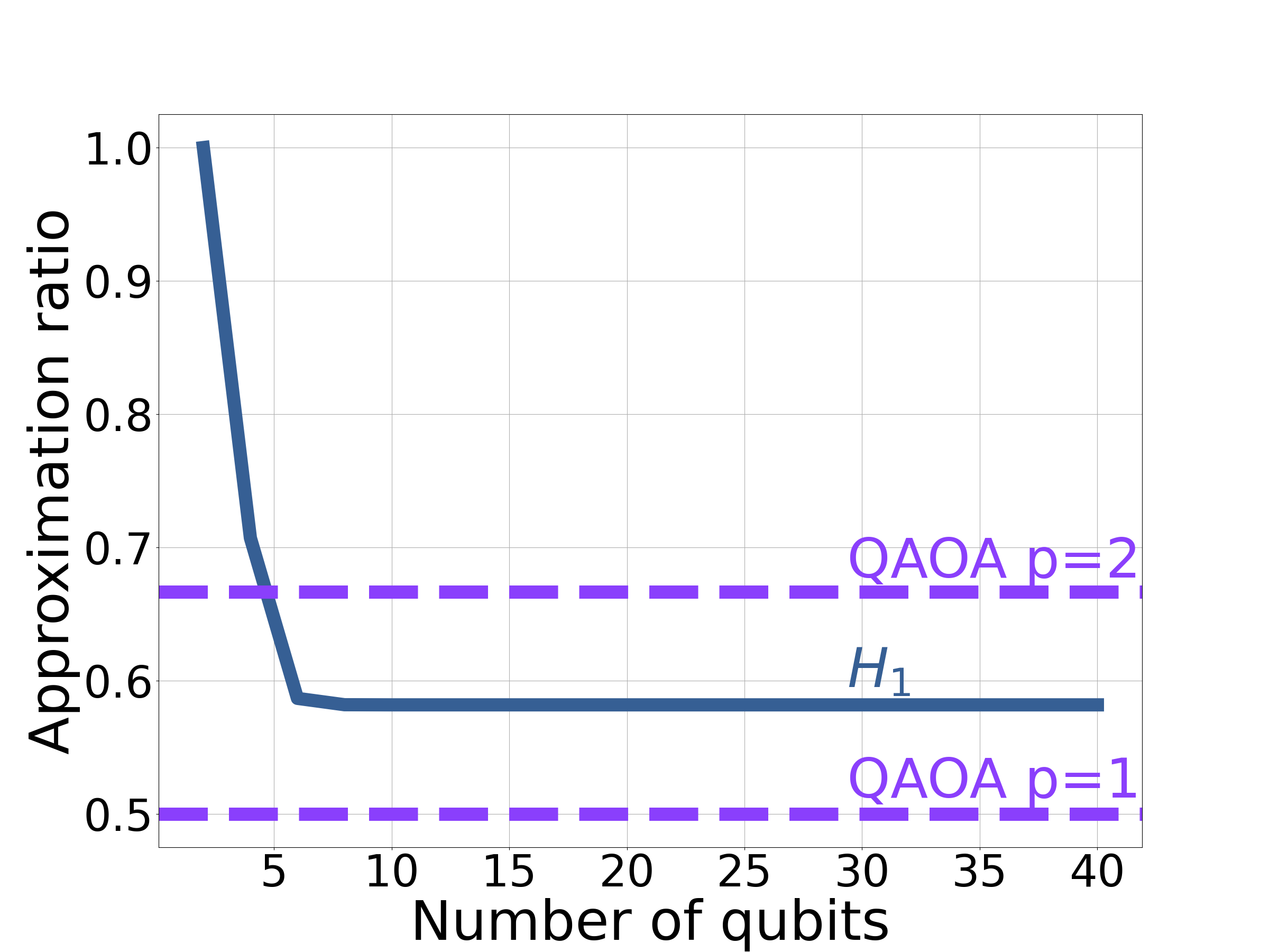

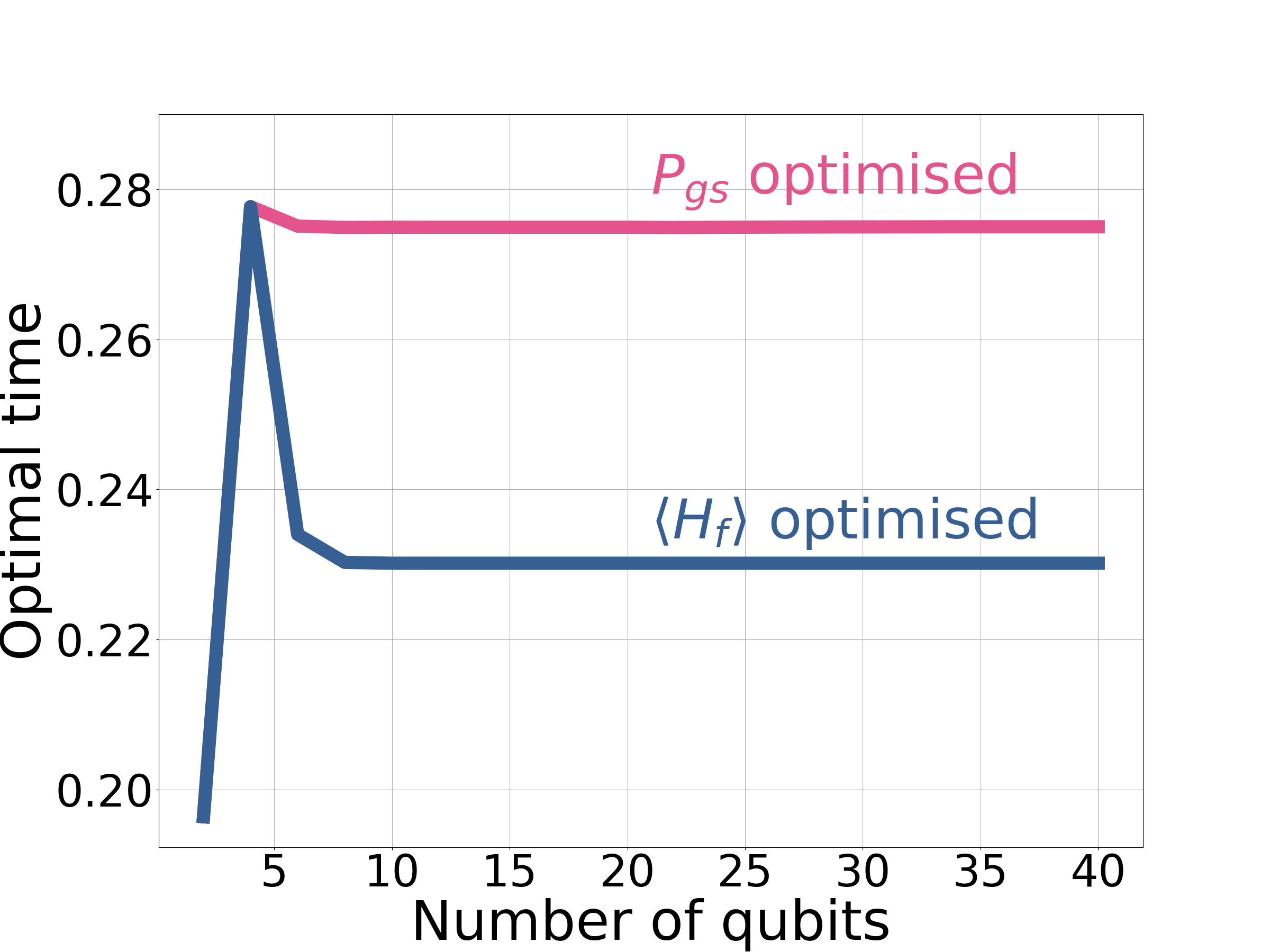
The key result of this section is shown in Fig. 3(a), showing the optimal approximation ratio versus problem size for even numbers of qubits only. The corresponding plot for odd numbers of qubits can be found in Appendix G. Notably the approximation ratio saturates for large problem sizes, achieving an approximation ratio of , compared to for QAOA . This is despite QAOA having two variational parameters, compared to the single variational parameter for . This behaviour is suggestive of optimising locally, since its approximation ratio is largely independent of problem size.
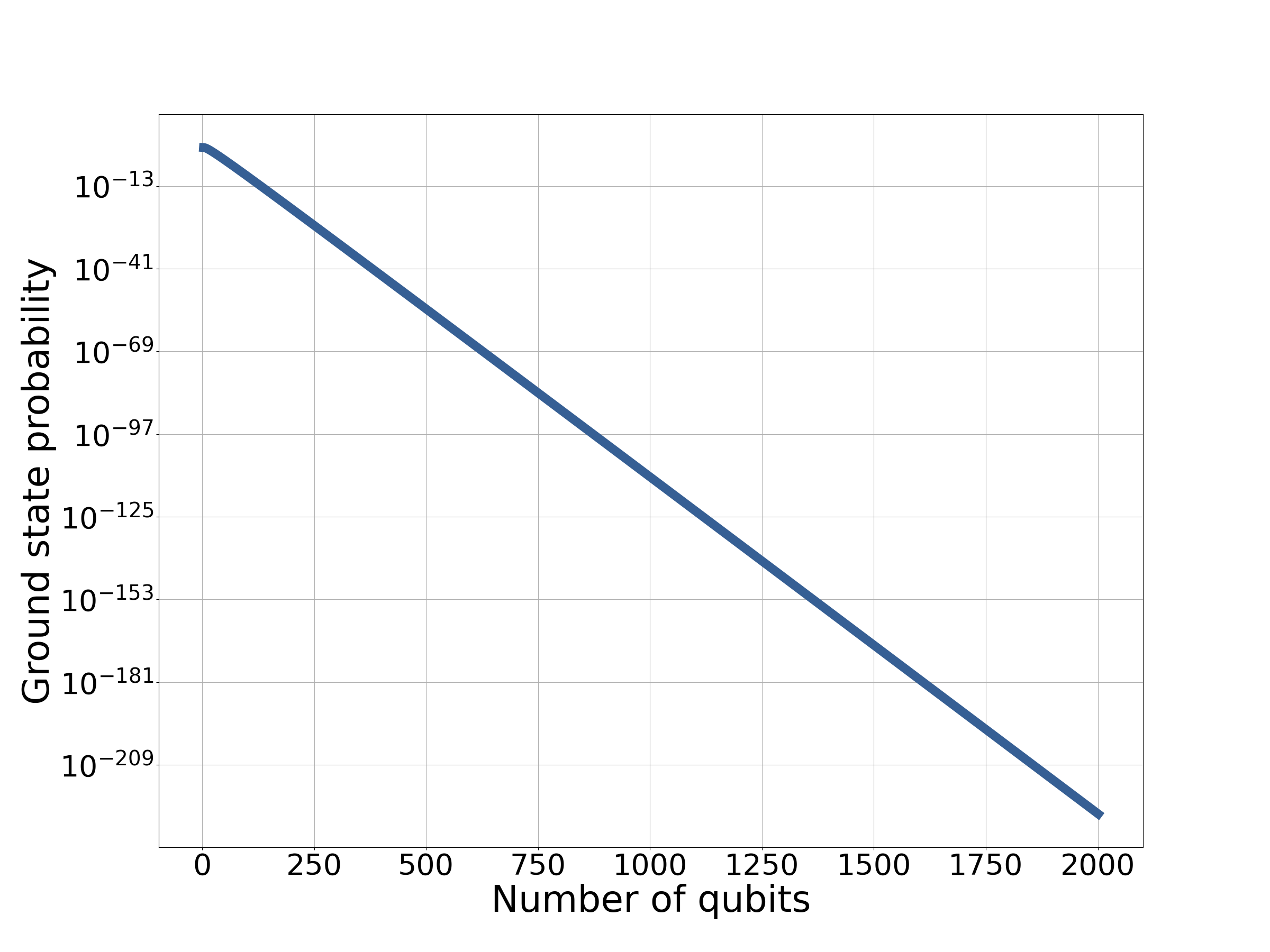
Despite MAX-CUT on two-regular graphs being an easy problem, the ground-state probability scales exponentially with problem size (Fig. 3(b)). This is not necessarily a problem, as we present as an approximate approach only. Optimising the performance to give the best ground-state probability provides a small gain in performance but does not change the overall exponential scaling. The optimal times for both approximation ratio and ground-state probability can be found in Fig. 3(c). Both times freeze out at constant values for problem sizes greater than 10 qubits.
We have demonstrated with MAX-CUT on two-regular graphs, at large problem sizes, that can provide a better approximation ratio than QAOA . We explore this comparison with QAOA further in Sec. 5.3.
5.2.3 Performance on MAX-CUT problems with three-regular graphs
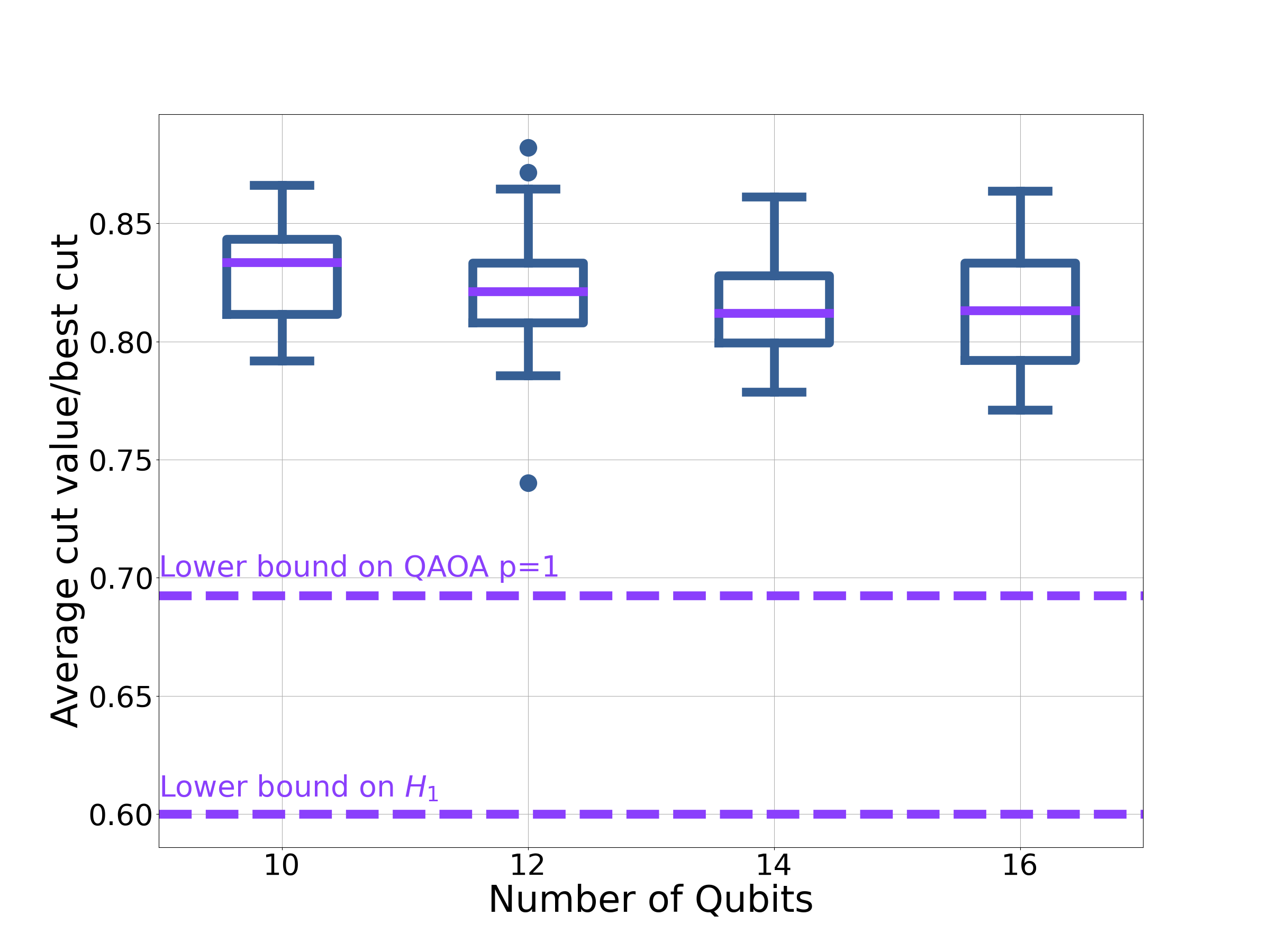
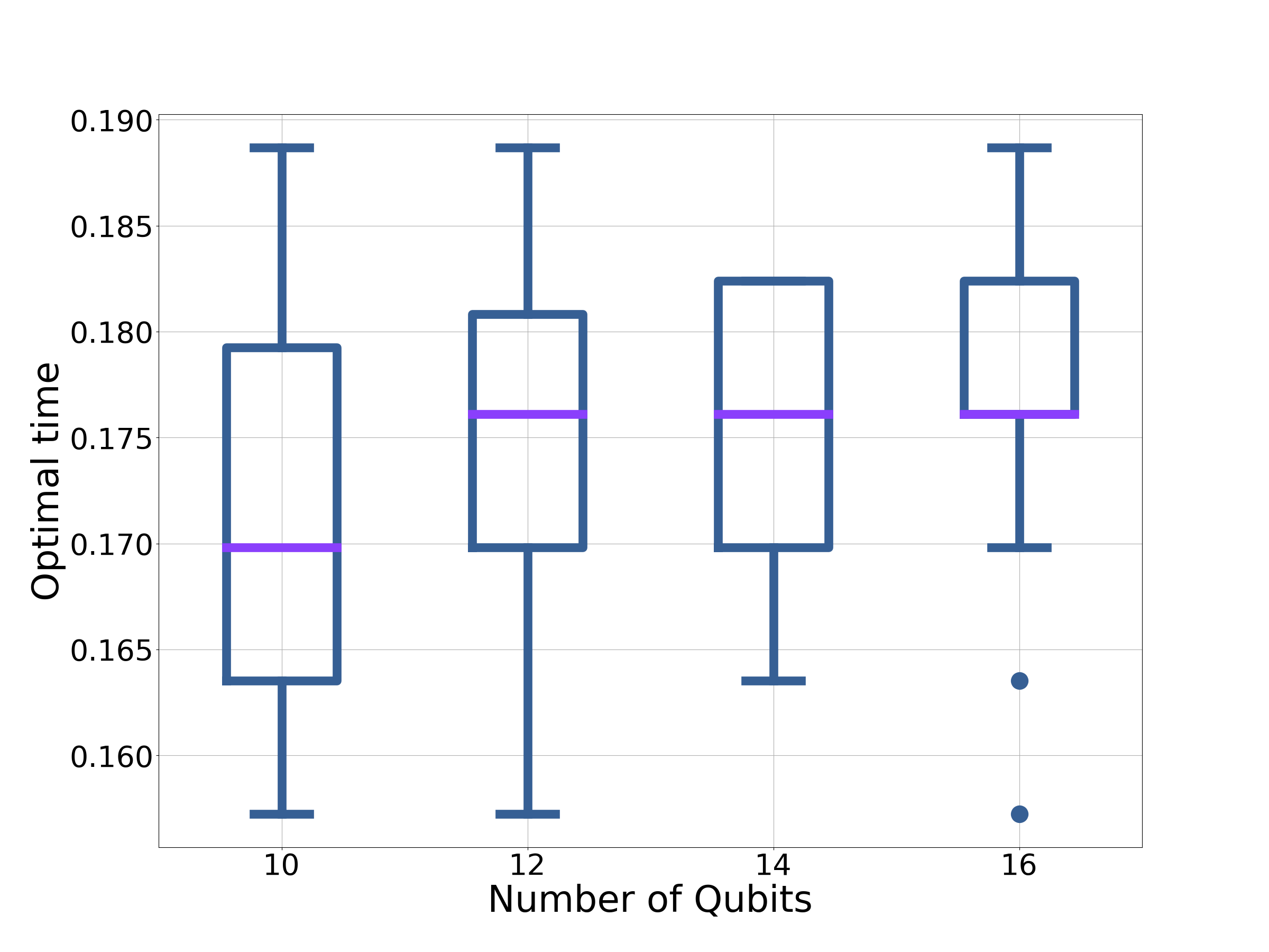
By exploiting locality in QA with short run-times, Braida et al. [61] were able to prove bounds on QA on MAX-CUT with three-regular graphs. Here we apply this approach to . For details of the method the reader is referred to [61] and for explicit details of this computation to Appendix H. We find that that finds at least times the best cut. Hence has a marginally better worst-case than QA (which is 0.5933 times the best cut [61]), when this method is applied. Both bounds are not necessarily (and unlikely to be) tight. Resorting to numerical simulation gives Fig. 4(a). Here we can see, for the random instances considered, that never does worse than the QAOA worst bound. Direct comparisons to QAOA can be found in Appendix I. Fig. 4(a) also shows that the approximation ratio of on three-regular graphs has little dependence on the problem size, again suggesting that it is optimising locally.
5.2.4 Numerical simulations on random instances of MAX-CUT
In the previous two sections we established the performance of on problems with a high degree of structure, allowing for more analytical investigation. In this section we explore the performance of numerically on MAX-CUT with random graphs. Consequently, we are restricted to exploring problem sizes that can be simulated classically. Further details about the numerics can be found in Appendix D.
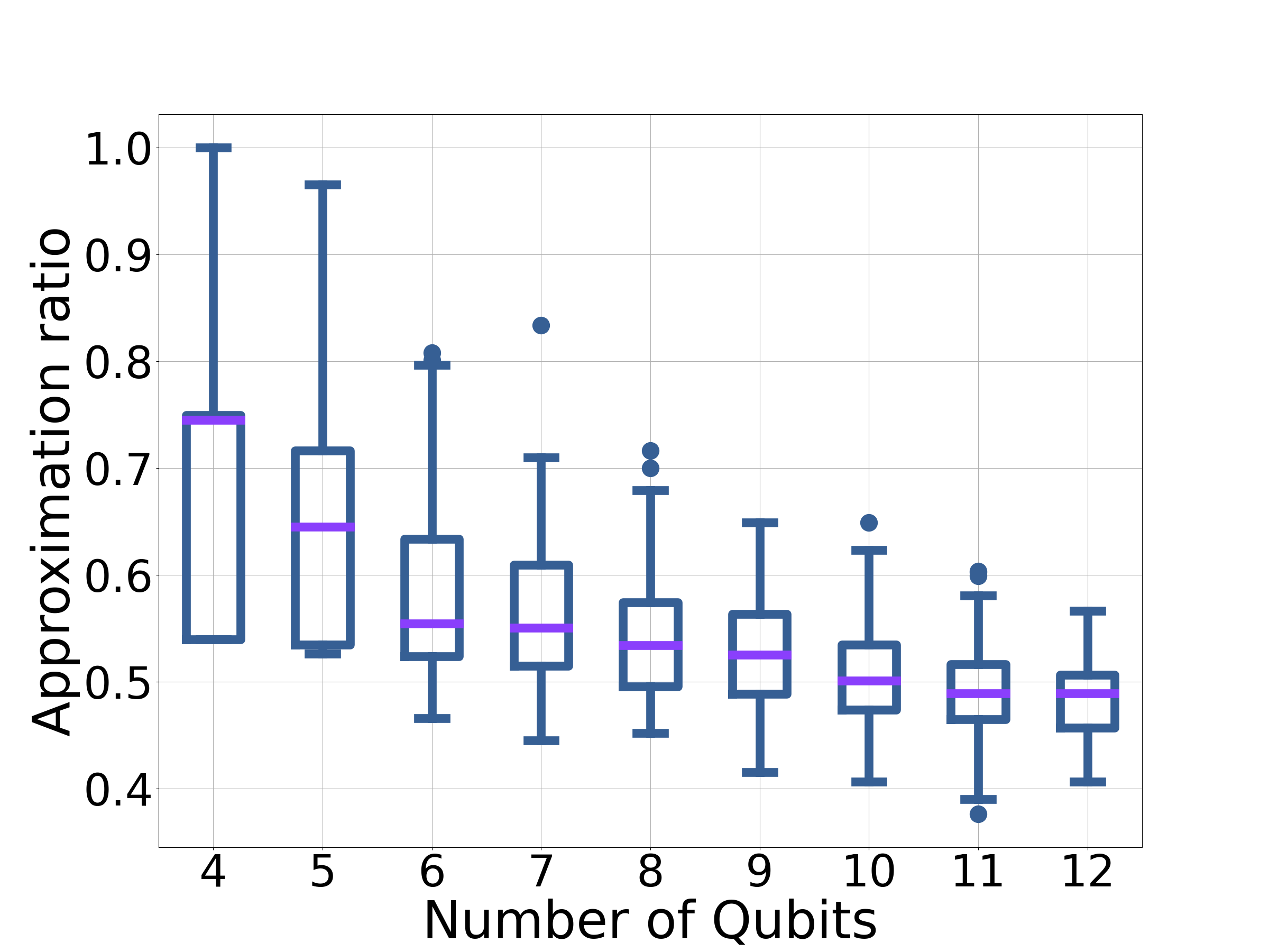
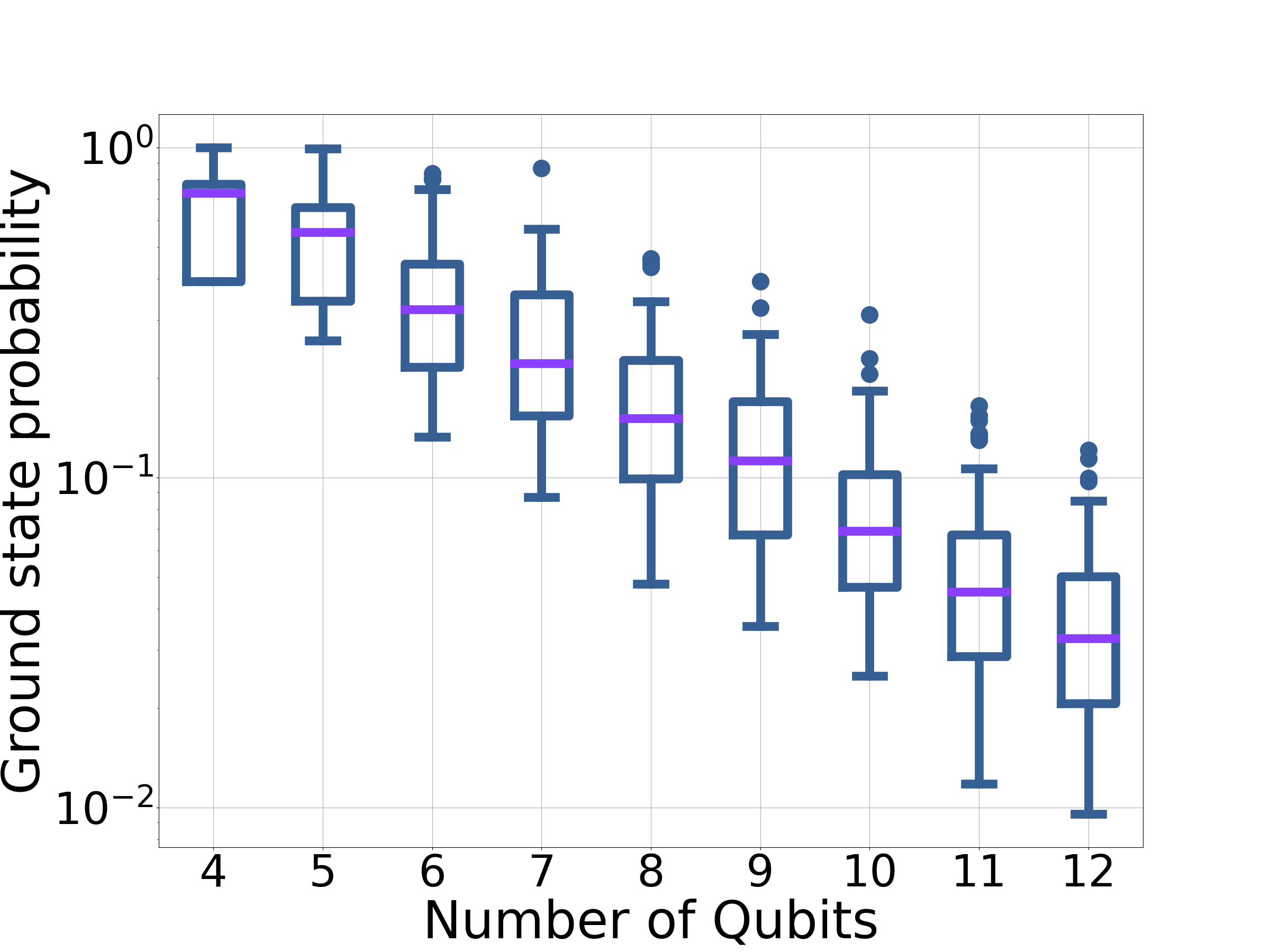
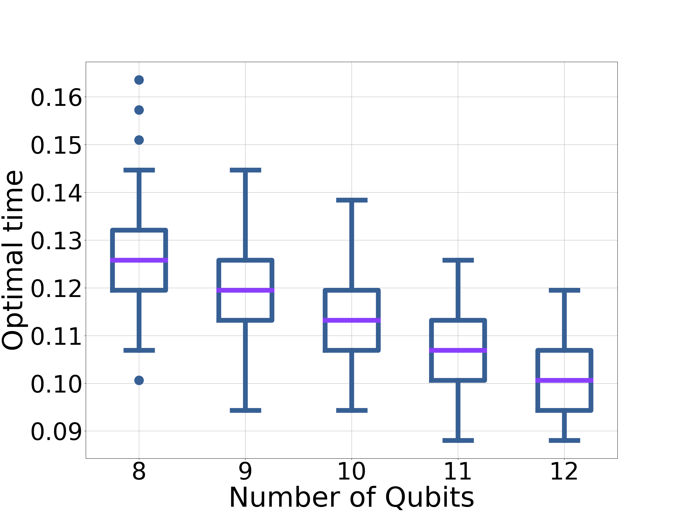
For each problem size we consider 100 randomly-generated instances. The results can be seen in Fig. 5. For each instance the time has been numerically optimised to maximise the approximation ratio within the interval . From Fig. 5 we draw some conclusions from the simulations, with the caveat that either much larger sizes need to be simulated and/or analytic work is required to fully substantiate the claims. On all the problems considered performed better than random guessing (which results in an approximation ratio of 0).
Focusing first on Fig. 5(a): there appears to be some evidence that the distribution of approximation ratios is becoming smaller as the problem size is increased. In addition the approximation ratio tends to a constant value, independent of the problem size. From analysing the regular graphs, it is reasonable to assume that is optimising locally. Therefore, we would expect the performance of to depend on the subgraphs in the problem. If the performance is limited by one, or a certain combination of subgraphs, then that would explain the constant approximation ratio. As the problem size is increased the chance of having an atypical combination of subgraphs is likely to decrease, resulting in a smaller distribution.
The ground-state probability shows a clear exponential dependence on problem size (Fig. 5(b)).
5.2.5 Estimating the optimal time
Presenting the application of as a variational approach begs the question of how to find good initial guesses for the time, , at which to measure the system. As previously noted the optimal time corresponds to the maximum approximation-ratio.
For our method we are not interested in finding the true maximum in approximation ratio. Sampling from a local maximum, close to is more achievable and reduces the time the system needs to be coherent. From Sec. 5.2.1 we expect the first turning point in approximation ratio after to be a local maximum. This is shown by Eq. 14, with all amplitudes flowing from higher energy states to lower energy states a Hamming distance of one away at . Further to this, throughout the work so far we have seen evidence of behaving locally. This local behaviour will allow us to motivate good initial guesses for . As is optimising locally, its performance does not depend on the graph as a whole, but only on subgraphs.
The optimal time for MAX-CUT on two-regular graphs was . Under the assumption that is behaving locally we can estimate the optimal times by considering a smaller subgraph. The subgraph in question is shown in Fig. 6(a). By numerically optimising for this subgraph with , we can find good estimates for the optimal . Optimising this subgraph, within the interval , gives . This estimate matches the optimal time well. Choosing a larger subgraph will give a better estimate on the time.
Fig. 4(b) shows the optimal time for the larger instances of three-regular graphs considered in Fig. 4(a). The range of optimal times varied very little between problem instances and problem sizes, centered around . As with the two-regular case we can examine subgraphs. In this case we consider the subgraph shown in Fig. 6(b). This is the subgraph that saturates the Lieb-Robinson bound (Appendix H). Numerically optimising for this subgraph with gives a time of . This again is a good estimate of the optimal time.
For problems with well understood local structure, such as regular graphs, we have shown that we can exploit this knowledge to provide reasonable estimates of the optimal times. These subgraphs are also of the same size used in finding the optimal time in QAOA [19].
For the MAX-CUT problems in Sec. 5.2.4, the optimal times can be found in Fig. 5(c). It appears that the optimal time tends to a constant value (or a small range of values), with . The optimal times are clustered together, suggesting good optimal times might be transferable between problem instances. This approach is common within the QAOA literature [62].
So far we have explored the performance of . We have demonstrated that can provide a better approximation ratio for MAX-CUT on two-regular graphs. The intuition gained by studying QAOA has been transferable to the understanding of . In the final part of this section we make some direct comparisons between QAOA and .
5.3 Direct numerical comparisons to QAOA p=1
We have established in the previous sections that operates in a local fashion. Calculating the optimal time for sub-graphs the same size as those involved in QAOA gave good estimates for the optimal time for larger problem sizes. Therefore it is reasonable to assume that sees a similar proportion of the graph as QAOA . Both approaches are variational with short run-times too. Since both approaches are using comparable resources, in this section we attempt to compare the two. Again we focus on the problems outlined in Sec. 4.
For two-regular graphs, the optimal time for QAOA is 2.4 times longer than the optimal time for for large problem sizes, despite providing a poorer approximation ratio.
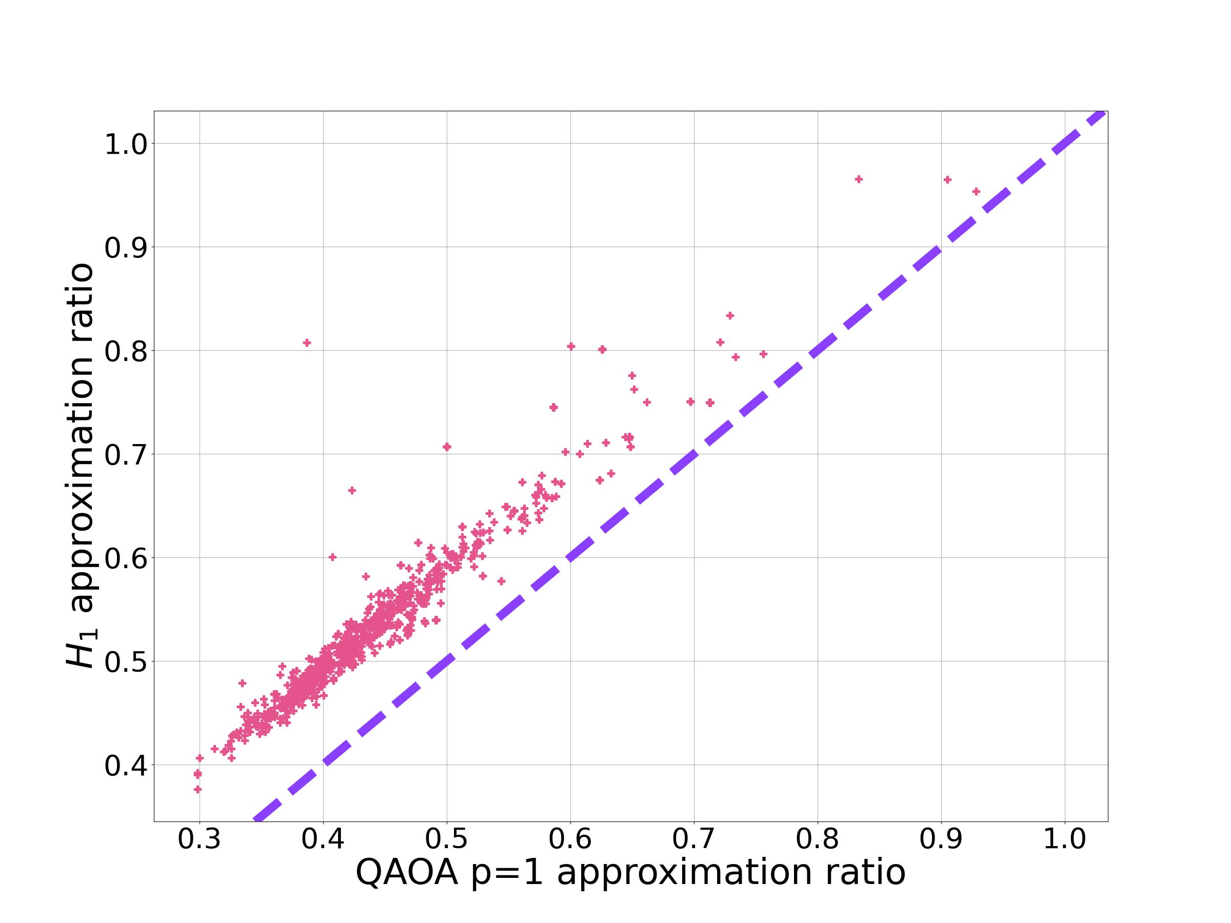

The results comparing and QAOA , for all the problem instances considered in Sec. 5.2.4, are shown in Fig. 7.
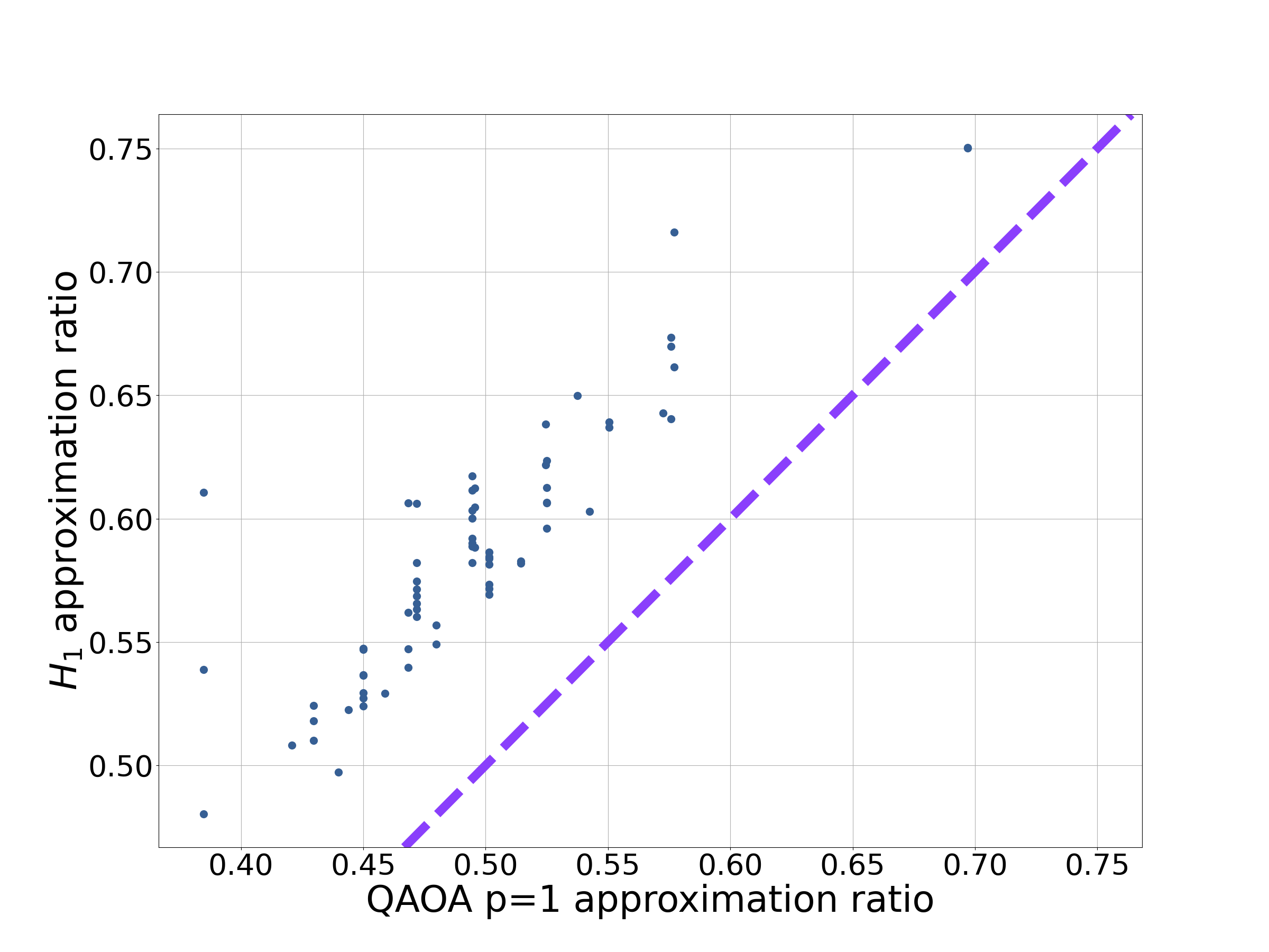
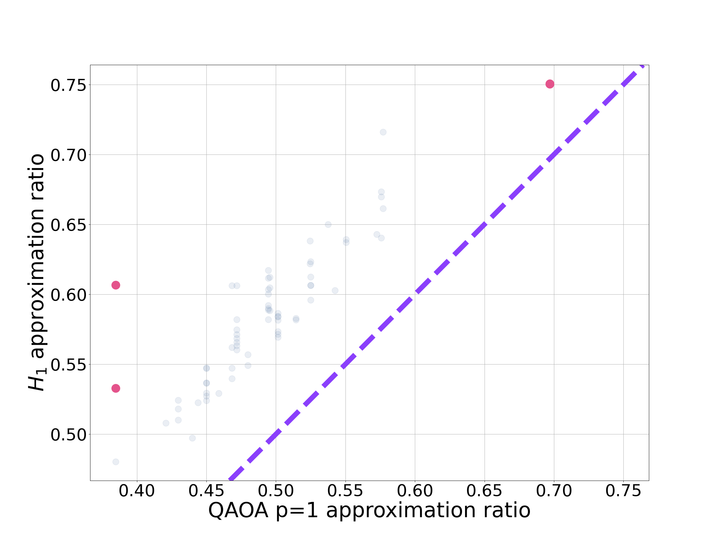
The approximation ratios for each approach are largely correlated, suggesting in general that harder problems for QAOA corresponded to harder problems for .For all instances considered, gave a greater than or equal to approximation ratio compared to QAOA (Fig. 7(a)).
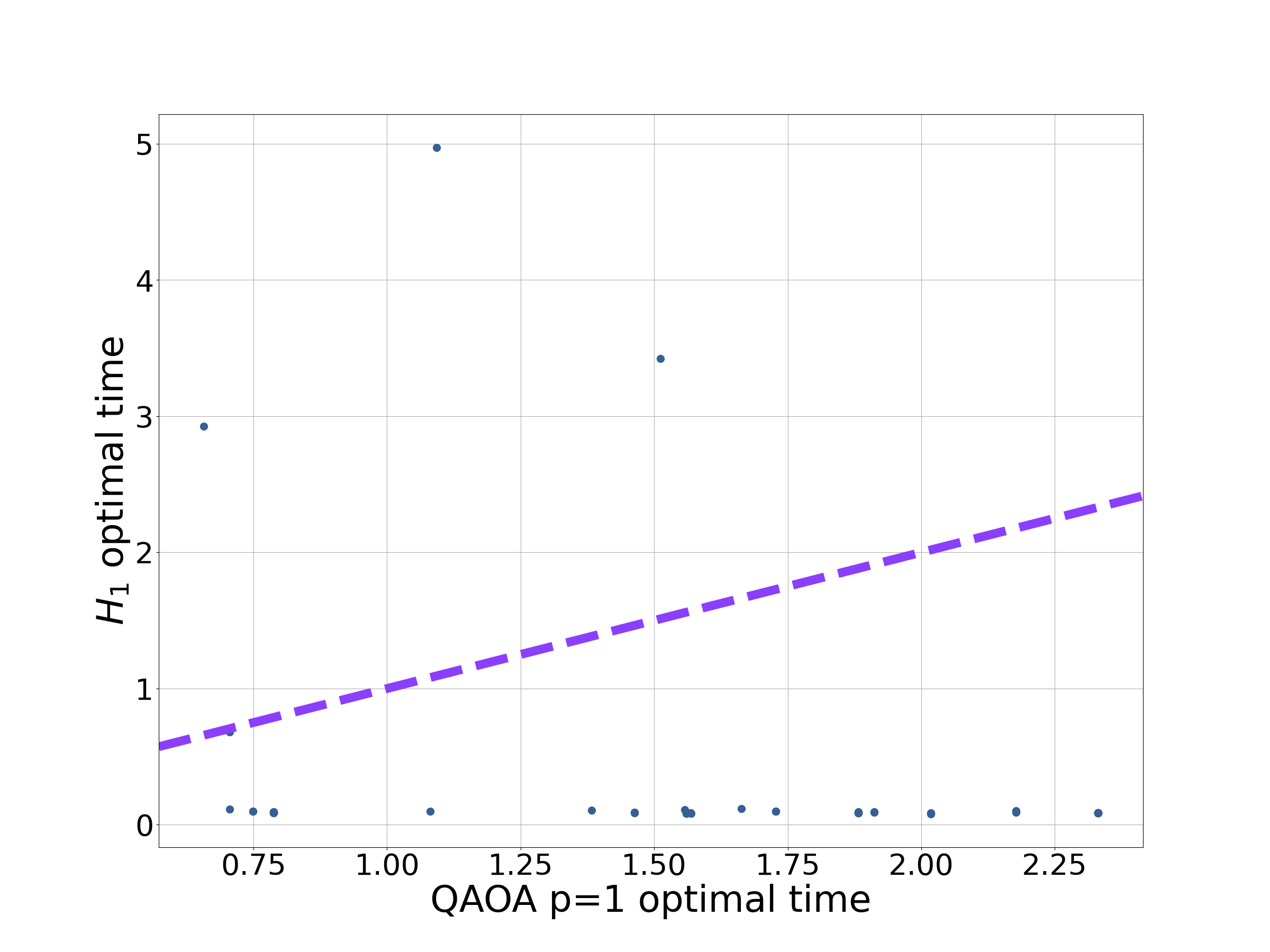
Turning now to the optimal time, had in the majority of cases the shorter optimal time (Fig. 7(b)). In Appendix J we elaborate further on the exceptions, that is the MAX-CUT problems that have longer run-times than QAOA p=1.
This section has numerically demonstrated that provides a better approximation ratio than QAOA in a significantly shorter time for the majority of instances considered, justifing our description of this this approach as rapid, which is crucial for NISQ implementation [28]. Given that, tends to provide a better approximation ratio, in a shorter time, with fewer variational parameters, it raises the question - does QAOA , the foundation of any QAOA circuit, make effective use of its afforded resources?
6 An improvement inspired by the Quantum Zermello problem
6.1 The approach
With QAOA it is clear how to get better approximation ratios, that is by increasing . It is less clear how to do this with . One suggestion might be to append this Hamiltonian to a QAOA circuit. However, the aim of this paper is to explore how Hamiltonians for optimal state-transfer can provide a guiding design principle. Therefore, in this section we explore adding another term, motivated by this new design principle, to to improve the approximation ratio.
In Sec. 3 we motivated from the optimal Hamiltonian by making the pragmatic substitutions and . Subsequently, we demonstrated that provides a reasonable performance. However, no longer closely followed the evolution under the optimal Hamiltonian. To partially correct for this error we add another term to the Hamiltonian:
| (19) |
Again, we make use of Hamiltonians for optimal state-transfer to motivate the form of . Finding the optimal Hamiltonian in the presence of an uncontrollable term in the Hamiltonian is known as the quantum Zermello (QZ) problem [55, 56, 57, 58].
In the rest of this section we expand on the details of the QZ problem. From the exact form of the optimal correction, , we then apply a series of approximations so that is time-independent and does not rely on knowledge of . This final Hamiltonian will be in Eq. 19.
The QZ problem, like the quantum brachistochrone problem, asks what is the Hamiltonian that transfers the system from to the final state in the shortest possible time. Unlike the quantum brachistochrone problem, part of the Hamiltonian is uncontrollable. In the case of a constant uncontrollable term, the total Hamiltonian can be written as:
| (20) |
where is the constant ‘quantum wind’ that cannot be changed and is the Hamiltonian we are free to vary. Typically, is understood as a noise term [63, 64]. Instead, here we will take to be to provide a favourable quantum wind that can provide an improvement on.
The optimal form of is (up to some factor) [56]:
| (21) |
where is the time and is the final time. The motivation for this equation can be found in Fig. 8. This Hamiltonian requires knowledge of the final state, so we introduce a series of approximations to make more amenable for implementation.
Since we know that the optimum evolution under tends to be short, we make the assumption that the total time is small. Therefore, we approximate the optimal correction with with
| (22) |
Introducing the commutator structure (Sec. 3) with the same pragmatic substitutions as before for gives:
| (23) |
where we have introduced the subscript to distinguish this Hamiltonian from prior to the substitutions. Expanding this expression in gives:
| (24) |
From the QZ problem we have motivated the form of the correction in Eq. 19. In spite of this we have no guarantee on its performance - to this end we carry out numerical simulations.
In both its philosophy and structure is reminiscent of shortcuts to adiabaticity (STA) [65]. In STA the aim is to modify the Hamiltonian in Eq. 1 to reach the adiabatic result in a shorter time, typically by appending to the standard QA Hamiltonian. The approach here is distinctly different for three key reasons, besides the initial starting point of Hamiltonian.
-
1.
The aim here is to do something distinctly different from , not to recover its behaviour in a shorter time.
-
2.
In the QZ-inspired approach we make use of the excited states, with the aim of finding approximate solutions, as opposed to exact solutions.
-
3.
Here we only consider time-independent Hamiltonians.
A clear downside to is the increased complexity, compared to say QAOA. However, if is decomposed into a QAOA-style circuit, the single free parameter in might translate to fewer free parameters in the QAOA circuit, allowing for easier optimisation.
6.2 Numerical simulations
6.2.1 MAX-CUT on two-regular graphs

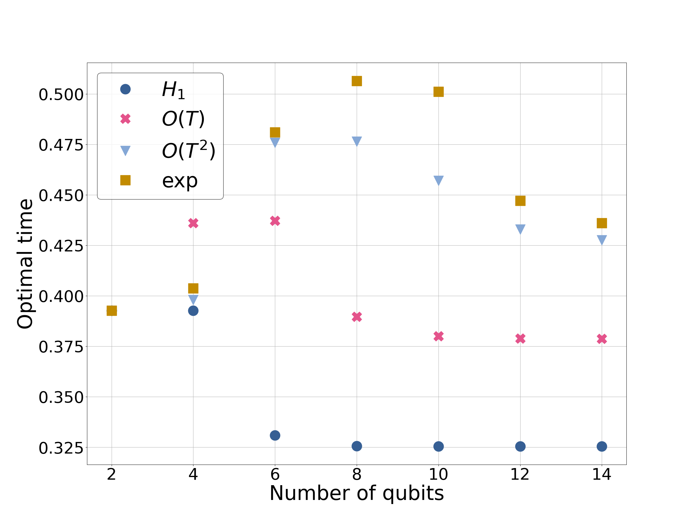
Here we focus on applying Eq. 24 up to various orders in to MAX-CUT on two-regular graphs with an even number of qubits. We focus on this problem as it is trivial to scale and the performance of QAOA and on this problem is well understood.
The results for MAX-CUT with two-regular graphs can be seen in Fig. 9(a). Increasing the expansion in appears to improve the approximation ratio. But the improvement is capped, shown by the data labelled ‘exp’. Notably, this approach with a single variational parameter at order is performing better than QAOA (with 6 variational parameters) for 10 qubits.
The optimal for the QZ-inspired Hamiltonians can be seen in Fig. 9(b). Again, the optimal time for each order in appears to be tending to a constant value, suggesting this approach is still acting in a local fashion. This is consistent with the approximation ratio plateauing. As we can see the QZ-inspired approach is still operating in a rapid fashion.
6.2.2 MAX-CUT on random graphs
To complete this section we examine the performance of the QZ-inspired approach (Eq. 24) to the randomly generated instances of MAX-CUT, detailed in Sec. 4.
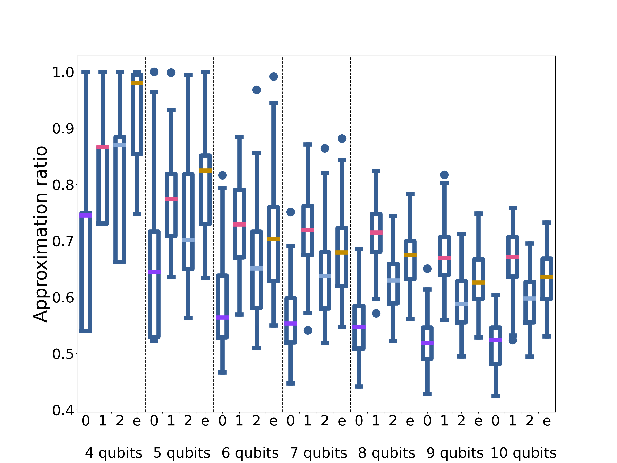
The results for different orders in for the approximation ratio can be seen in Fig. 10(a). All the QZ-inspired approaches provide an improvement on the original Hamiltonian, indexed by 0 in the figures. However, the performance is not monotonically increasing with the order of the expansion. This is not unusual for a Taylor series of an oscillatory function. Consequently, achieving better approximation ratios is not as simple as increasing the order of . At the same time, this means that it is not necessary to go to high orders in , with very non-local terms, to achieve a significant gain in performance. For example, in going to first order achieves a substantial improvement.
The optimal times for the QZ-inspired approach can be found in Fig. 10(b). For clarity we only show the optimal times for the larger problem instances. As with the optimal times are clustered for a given order. The lack of dependence on problem size for optimal times and approximation ratios suggests that the QZ-inspired approach is still optimising locally. Compared to the case, the operators have a larger support. Despite optimising locally, they are optimising less locally than , hence the increased performance.
Here we have numerically demonstrated that the QZ-inspired approach can provide an improvement over , suggesting how this new design philosophy might be extended. The numerics also suggest that going to first order may provide the best possible advantage.

7 Using knowledge of the initial state
As introduced in Sec. 3, in this section we exploit our knowledge of the initial state and evaluate the performance of
| (25) |
within the QA-framework. We take to be a real function such that:
| (26) |
where and are the eigenvectors and associated eigenvalues of .
Evolution under can be calculated analytically - the details can be found in Appendix K. By evolving the state:
| (27) |
can be reached. Indeed will generate linear superpositions of and only.
Assuming that the state is prepared, then the probability of finding the ground-state is
| (28) |
where is the ground-state degeneracy and the associated energy. If is the identity, then scales approximately as and might scale with . Hence the ground state probability will scale as . Indeed if , where is some positive integer, then the ground state probability might scale as . This is an improvement over random guessing, but still with exponential scaling. This may be of some practical benefit, depending on the computational cost of calculating . If is the projector onto the ground-state then (as expected).
Calculating the expectation of for gives:
| (29) |
Here we can see that will be dominated by states for which is large. If is the identify this most likely means low energy states and high energy states. Hence, we do not expect a good approximation ratio. This provides some insight into Sec. 5.2.2 where the observed peak in ground-state probability did not coincide with the optimal approximation ratio.
This approach has the potential to provide a modest practical speed-up with a polynomial prefactor on the hardest problems. However, the success of this approach depends on the (unlikely) feasibility of implementing and . It does however provide further evidence of the power of commutators for designing algorithms to tackle optimisation problems.
8 Discussion and Conclusion
Designing quantum algorithms to tackle combinatorial optimisation problems, especially within the NISQ framework, remains a challenge. Many algorithms have used AQO in their inspiration, such as in the choice of Hamiltonians. In this paper we have explored using optimal Hamiltonians as a guiding design principle.
With , the commutator between and , we demonstrated that we can outperform QAOA p=1, with fewer resources. The short run-times which do not appear to scale with problem size suggest that this approach is acting locally. An effective Lieb-Robinson bound prevents the information about the problem propagating instantaneously [66, 67]. This helps provide some insights into the performance of :
-
•
In the local regime, the effective local Hilbert space is smaller than the global Hilbert space, consequently will be a better approximation of the optimal Hamiltonian. This accounts for why we might expect to work better on short run-times.
-
•
A local algorithm is unlikely to be able to solve an optimisation problem, as it cannot see the whole graph. It follows that such an approach would have poor scaling of the ground-state probability.
Due to the local nature of we were able to utilise some analytical tricks to assist the numerical assessment of its performance, allowing for some guarantee of the performance of the approach on large problem sizes. The techniques used had already been developed or deployed by the continuous-time quantum computing community in the context of QA/QAOA, indicative of the wide applicability of the tools being developed to assess these algorithms.
Local approaches have clear advantages in NISQ-era computations. The short run-times put fewer demands on the coherence times of the device. The local nature can also help mitigate some errors. If, for example, there is a control misspecification in one part of the Hamiltonian this is unlikely to propagate through the whole system and affect the entire computation.
Buoyed by the relative success of utilizing Hamiltonians for optimal state-transfer we turned to the quantum Zermello problem to help find improvements. These Hamiltonians compromised a single variational parameter and short run-times, for increased complexity in the Hamiltonian. Again, the saturation of the optimal time suggest these approaches are still operating locally.
The success of this approach, within the NISQ era, will depend on the feasibility of implementing these Hamiltonians. This might be achieved through decomposition into a product formula [68] for gate based approaches, resulting in a QAOA like circuit. Alternatively, one could attempt to explicitly engineer the interactions involved. Indeed, for exponentially scaling problems, implementing these Hamiltonians for short times could be less challenging then maintaining coherence for exponentially increasing times.
Although the results of this paper are not fully conclusive, it has shown that by considering Hamiltonians for optimal state-transfer we can develop promising new algorithms. We hope the results presented in this paper will encourage further work into the success of these Hamiltonians. There is scope for taking this work further. This could include changing the choice of , exploiting our observation that any stoquastic Hamiltonian can lead to an increase in ground state probability. For we have only explored problems with trivial Ising encodings. There is scope to explore new encodings such as LHZ [69] or Domain-wall [70] encodings. Such encodings will result in different and presumably distinct dynamics.
Acknowledgments
We gratefully acknowledge Filip Wudarski, Glen Mbeng, Henry Chew, Natasha Feinstein, and Sougato Bose for inspiring discussion and helpful comments. This work was supported by the Engineering and Physical Sciences Research Council through the Centre for Doctoral Training in Delivering Quantum Tech- nologies [grant number EP/S021582/1] and the ESPRC Hub in Quantum Computing and Simulation [grant number EP/T001062/1]. For the purpose of open access, the author has applied a Creative Commons Attribution (CC BY) licence to any Author Accepted Manuscript version arising.
References
- [1] Christos H. Papadimitriou and Kenneth Steiglitz. “Combinatorial optimization: Algorithms and complexity”. Dover Publications. (1981).
- [2] M. H. S. Amin. “Consistency of the adiabatic theorem”. Phys. Rev. Lett. 102, 220401 (2009).
- [3] Ben W. Reichardt. “The quantum adiabatic optimization algorithm and local minima”. In Proceedings of the Thirty-Sixth Annual ACM Symposium on Theory of Computing. Page 502–510. STOC ’04New York, NY, USA (2004). Association for Computing Machinery.
- [4] B. Apolloni, C. Carvalho, and D. de Falco. “Quantum stochastic optimization”. Stochastic Processes and their Applications 33, 233–244 (1989).
- [5] Edward Farhi, Jeffrey Goldstone, Sam Gutmann, and Michael Sipser. “Quantum computation by adiabatic evolution” (2000). arXiv:0001106.
- [6] Tadashi Kadowaki and Hidetoshi Nishimori. “Quantum annealing in the transverse ising model”. Phys. Rev. E 58, 5355–5363 (1998).
- [7] A.B. Finnila, M.A. Gomez, C. Sebenik, C. Stenson, and J.D. Doll. “Quantum annealing: A new method for minimizing multidimensional functions”. Chemical Physics Letters 219, 343–348 (1994).
- [8] Tameem Albash and Daniel A. Lidar. “Adiabatic quantum computation”. Reviews of Modern Physics90 (2018).
- [9] N. G. Dickson, M. W. Johnson, M. H. Amin, R. Harris, F. Altomare, A. J. Berkley, P. Bunyk, J. Cai, E. M. Chapple, P. Chavez, F. Cioata, T. Cirip, P. deBuen, M. Drew-Brook, C. Enderud, S. Gildert, F. Hamze, J. P. Hilton, E. Hoskinson, K. Karimi, E. Ladizinsky, N. Ladizinsky, T. Lanting, T. Mahon, R. Neufeld, T. Oh, I. Perminov, C. Petroff, A. Przybysz, C. Rich, P. Spear, A. Tcaciuc, M. C. Thom, E. Tolkacheva, S. Uchaikin, J. Wang, A. B. Wilson, Z. Merali, and G. Rose. “Thermally assisted quantum annealing of a 16-qubit problem”. Nature Communications 4, 1903 (2013).
- [10] E. J. Crosson and D. A. Lidar. “Prospects for quantum enhancement with diabatic quantum annealing”. Nature Reviews Physics 3, 466–489 (2021).
- [11] Louis Fry-Bouriaux, Daniel T. O’Connor, Natasha Feinstein, and Paul A. Warburton. “Locally suppressed transverse-field protocol for diabatic quantum annealing”. Phys. Rev. A 104, 052616 (2021).
- [12] Rolando D. Somma, Daniel Nagaj, and Mária Kieferová. “Quantum speedup by quantum annealing”. Phys. Rev. Lett. 109, 050501 (2012).
- [13] Edward Farhi, Jeffrey Goldston, David Gosset, Sam Gutmann, Harvey B. Meyer, and Peter Shor. “Quantum adiabatic algorithms, small gaps, and different paths”. Quantum Info. Comput. 11, 181–214 (2011).
- [14] Lishan Zeng, Jun Zhang, and Mohan Sarovar. “Schedule path optimization for adiabatic quantum computing and optimization”. Journal of Physics A: Mathematical and Theoretical 49, 165305 (2016).
- [15] Edward Farhi, Jeffrey Goldstone, and Sam Gutmann. “Quantum adiabatic evolution algorithms with different paths” (2002). arXiv:quant-ph/0208135.
- [16] Natasha Feinstein, Louis Fry-Bouriaux, Sougato Bose, and P. A. Warburton. “Effects of xx-catalysts on quantum annealing spectra with perturbative crossings” (2022). arXiv:2203.06779.
- [17] Elizabeth Crosson, Edward Farhi, Cedric Yen-Yu Lin, Han-Hsuan Lin, and Peter Shor. “Different strategies for optimization using the quantum adiabatic algorithm” (2014). arXiv:1401.7320.
- [18] Vicky Choi. “Essentiality of the non-stoquastic hamiltonians and driver graph design in quantum optimization annealing” (2021). arXiv:2105.02110.
- [19] Edward Farhi, Jeffrey Goldstone, and Sam Gutmann. “A quantum approximate optimization algorithm” (2014). arXiv:1411.4028.
- [20] Adam Callison, Nicholas Chancellor, Florian Mintert, and Viv Kendon. “Finding spin glass ground states using quantum walks”. New Journal of Physics 21, 123022 (2019).
- [21] Viv Kendon. “How to compute using quantum walks”. Electronic Proceedings in Theoretical Computer Science 315, 1–17 (2020).
- [22] Adam Callison, Max Festenstein, Jie Chen, Laurentiu Nita, Viv Kendon, and Nicholas Chancellor. “Energetic perspective on rapid quenches in quantum annealing”. PRX Quantum 2, 010338 (2021).
- [23] James G. Morley, Nicholas Chancellor, Sougato Bose, and Viv Kendon. “Quantum search with hybrid adiabatic–quantum-walk algorithms and realistic noise”. Physical Review A99 (2019).
- [24] Dorje C Brody and Daniel W Hook. “On optimum hamiltonians for state transformations”. Journal of Physics A: Mathematical and General 39, L167–L170 (2006).
- [25] J.R. Johansson, P.D. Nation, and Franco Nori. “Qutip: An open-source python framework for the dynamics of open quantum systems”. Computer Physics Communications 183, 1760–1772 (2012).
- [26] J.R. Johansson, P.D. Nation, and Franco Nori. “Qutip 2: A python framework for the dynamics of open quantum systems”. Computer Physics Communications 184, 1234–1240 (2013).
- [27] MD Sajid Anis, Abby-Mitchell, Héctor Abraham, and AduOffei et al. “Qiskit: An open-source framework for quantum computing” (2021).
- [28] John Preskill. “Quantum computing in the NISQ era and beyond”. Quantum 2, 79 (2018).
- [29] Philipp Hauke, Helmut G Katzgraber, Wolfgang Lechner, Hidetoshi Nishimori, and William D Oliver. “Perspectives of quantum annealing: methods and implementations”. Reports on Progress in Physics 83, 054401 (2020).
- [30] Leo Zhou, Sheng-Tao Wang, Soonwon Choi, Hannes Pichler, and Mikhail D. Lukin. “Quantum approximate optimization algorithm: Performance, mechanism, and implementation on near-term devices”. Phys. Rev. X 10, 021067 (2020).
- [31] Stuart Hadfield, Zhihui Wang, Bryan O'Gorman, Eleanor Rieffel, Davide Venturelli, and Rupak Biswas. “From the quantum approximate optimization algorithm to a quantum alternating operator ansatz”. Algorithms 12, 34 (2019).
- [32] Matthew P. Harrigan, Kevin J. Sung, Matthew Neeley, and Kevin J. Satzinger et al. “Quantum approximate optimization of non-planar graph problems on a planar superconducting processor”. Nature Physics 17, 332–336 (2021).
- [33] T. M. Graham, Y. Song, J. Scott, C. Poole, L. Phuttitarn, K. Jooya, P. Eichler, X. Jiang, A. Marra, B. Grinkemeyer, M. Kwon, M. Ebert, J. Cherek, M. T. Lichtman, M. Gillette, J. Gilbert, D. Bowman, T. Ballance, C. Campbell, E. D. Dahl, O. Crawford, N. S. Blunt, B. Rogers, T. Noel, and M. Saffman. “Multi-qubit entanglement and algorithms on a neutral-atom quantum computer”. Nature 604, 457–462 (2022).
- [34] J. S. Otterbach, R. Manenti, N. Alidoust, A. Bestwick, M. Block, B. Bloom, S. Caldwell, N. Didier, E. Schuyler Fried, S. Hong, P. Karalekas, C. B. Osborn, A. Papageorge, E. C. Peterson, G. Prawiroatmodjo, N. Rubin, Colm A. Ryan, D. Scarabelli, M. Scheer, E. A. Sete, P. Sivarajah, Robert S. Smith, A. Staley, N. Tezak, W. J. Zeng, A. Hudson, Blake R. Johnson, M. Reagor, M. P. da Silva, and C. Rigetti. “Unsupervised machine learning on a hybrid quantum computer” (2017). arXiv:1712.05771.
- [35] Lucas T. Brady, Christopher L. Baldwin, Aniruddha Bapat, Yaroslav Kharkov, and Alexey V. Gorshkov. “Optimal protocols in quantum annealing and quantum approximate optimization algorithm problems”. Phys. Rev. Lett. 126, 070505 (2021).
- [36] Lucas T. Brady, Lucas Kocia, Przemyslaw Bienias, Aniruddha Bapat, Yaroslav Kharkov, and Alexey V. Gorshkov. “Behavior of analog quantum algorithms” (2021). arXiv:2107.01218.
- [37] Xinyu Fei, Lucas T. Brady, Jeffrey Larson, Sven Leyffer, and Siqian Shen. “Binary control pulse optimization for quantum systems”. Quantum 7, 892 (2023).
- [38] Lorenzo Campos Venuti, Domenico D’Alessandro, and Daniel A. Lidar. “Optimal control for quantum optimization of closed and open systems”. Physical Review Applied16 (2021).
- [39] M.A. Nielsen. “A geometric approach to quantum circuit lower bounds”. Quantum Information and Computation 6, 213–262 (2006).
- [40] Michael A. Nielsen, Mark R. Dowling, Mile Gu, and Andrew C. Doherty. “Quantum computation as geometry”. Science 311, 1133–1135 (2006).
- [41] M.R. Dowling and M.A. Nielsen. “The geometry of quantum computation”. Quantum Information and Computation 8, 861–899 (2008).
- [42] Alberto Carlini, Akio Hosoya, Tatsuhiko Koike, and Yosuke Okudaira. “Time-optimal quantum evolution”. Phys. Rev. Lett. 96, 060503 (2006).
- [43] Alberto Carlini, Akio Hosoya, Tatsuhiko Koike, and Yosuke Okudaira. “Time-optimal unitary operations”. Physical Review A75 (2007).
- [44] A. T. Rezakhani, W.-J. Kuo, A. Hamma, D. A. Lidar, and P. Zanardi. “Quantum adiabatic brachistochrone”. Physical Review Letters103 (2009).
- [45] Xiaoting Wang, Michele Allegra, Kurt Jacobs, Seth Lloyd, Cosmo Lupo, and Masoud Mohseni. “Quantum brachistochrone curves as geodesics: Obtaining accurate minimum-time protocols for the control of quantum systems”. Phys. Rev. Lett. 114, 170501 (2015).
- [46] Hiroaki Wakamura and Tatsuhiko Koike. “A general formulation of time-optimal quantum control and optimality of singular protocols”. New Journal of Physics 22, 073010 (2020).
- [47] Ding Wang, Haowei Shi, and Yueheng Lan. “Quantum brachistochrone for multiple qubits”. New Journal of Physics 23, 083043 (2021).
- [48] Alan C. Santos, C. J. Villas-Boas, and R. Bachelard. “Quantum adiabatic brachistochrone for open systems”. Phys. Rev. A 103, 012206 (2021).
- [49] Jing Yang and Adolfo del Campo. “Minimum-time quantum control and the quantum brachistochrone equation” (2022). arXiv:2204.12792.
- [50] J. Anandan and Y. Aharonov. “Geometry of quantum evolution”. Phys. Rev. Lett. 65, 1697–1700 (1990).
- [51] Alberto Peruzzo, Jarrod McClean, Peter Shadbolt, Man-Hong Yung, Xiao-Qi Zhou, Peter J. Love, Alán Aspuru-Guzik, and Jeremy L. O’Brien. “A variational eigenvalue solver on a photonic quantum processor”. Nature Communications 5, 4213 (2014).
- [52] Dmitry A. Fedorov, Bo Peng, Niranjan Govind, and Yuri Alexeev. “VQE method: a short survey and recent developments”. Materials Theory6 (2022).
- [53] Li Li, Minjie Fan, Marc Coram, Patrick Riley, and Stefan Leichenauer. “Quantum optimization with a novel gibbs objective function and ansatz architecture search”. Phys. Rev. Research 2, 023074 (2020).
- [54] Panagiotis Kl. Barkoutsos, Giacomo Nannicini, Anton Robert, Ivano Tavernelli, and Stefan Woerner. “Improving variational quantum optimization using CVaR”. Quantum 4, 256 (2020).
- [55] Dorje C. Brody and David M. Meier. “Solution to the quantum zermelo navigation problem”. Phys. Rev. Lett. 114, 100502 (2015).
- [56] Dorje C Brody, Gary W Gibbons, and David M Meier. “Time-optimal navigation through quantum wind”. New Journal of Physics 17, 033048 (2015).
- [57] Benjamin Russell and Susan Stepney. “Zermelo navigation and a speed limit to quantum information processing”. Phys. Rev. A 90, 012303 (2014).
- [58] Benjamin Russell and Susan Stepney. “Zermelo navigation in the quantum brachistochrone”. Journal of Physics A: Mathematical and Theoretical 48, 115303 (2015).
- [59] Sergey Bravyi and Barbara Terhal. “Complexity of stoquastic frustration-free hamiltonians”. SIAM Journal on Computing 39, 1462–1485 (2010).
- [60] Glen Bigan Mbeng, Rosario Fazio, and Giuseppe Santoro. “Quantum annealing: a journey through digitalization, control, and hybrid quantum variational schemes” (2019). arXiv:1906.08948.
- [61] Arthur Braida, Simon Martiel, and Ioan Todinca. “On constant-time quantum annealing and guaranteed approximations for graph optimization problems”. Quantum Science and Technology 7, 045030 (2022).
- [62] Alexey Galda, Xiaoyuan Liu, Danylo Lykov, Yuri Alexeev, and Ilya Safro. “Transferability of optimal qaoa parameters between random graphs”. In 2021 IEEE International Conference on Quantum Computing and Engineering (QCE). Pages 171–180. (2021).
- [63] M. Lapert, Y. Zhang, M. Braun, S. J. Glaser, and D. Sugny. “Singular extremals for the time-optimal control of dissipative spin particles”. Phys. Rev. Lett. 104, 083001 (2010).
- [64] Victor Mukherjee, Alberto Carlini, Andrea Mari, Tommaso Caneva, Simone Montangero, Tommaso Calarco, Rosario Fazio, and Vittorio Giovannetti. “Speeding up and slowing down the relaxation of a qubit by optimal control”. Phys. Rev. A 88, 062326 (2013).
- [65] D. Guéry-Odelin, A. Ruschhaupt, A. Kiely, E. Torrontegui, S. Martínez-Garaot, and J. G. Muga. “Shortcuts to adiabaticity: Concepts, methods, and applications”. Rev. Mod. Phys. 91, 045001 (2019).
- [66] Elliott H. Lieb and Derek W. Robinson. “The finite group velocity of quantum spin systems”. Communications in Mathematical Physics 28, 251–257 (1972).
- [67] Zhiyuan Wang and Kaden R.A. Hazzard. “Tightening the lieb-robinson bound in locally interacting systems”. PRX Quantum 1, 010303 (2020).
- [68] Andrew M. Childs and Nathan Wiebe. “Product formulas for exponentials of commutators”. Journal of Mathematical Physics 54, 062202 (2013).
- [69] Wolfgang Lechner, Philipp Hauke, and Peter Zoller. “A quantum annealing architecture with all-to-all connectivity from local interactions”. Science Advances1 (2015).
- [70] Nicholas Chancellor. “Domain wall encoding of discrete variables for quantum annealing and QAOA”. Quantum Science and Technology 4, 045004 (2019).
- [71] Helmut G. Katzgraber, Firas Hamze, Zheng Zhu, Andrew J. Ochoa, and H. Munoz-Bauza. “Seeking quantum speedup through spin glasses: The good, the bad, and the ugly”. Physical Review X5 (2015).
- [72] M.R. Garey, D.S. Johnson, and L. Stockmeyer. “Some simplified np-complete graph problems”. Theoretical Computer Science 1, 237–267 (1976).
- [73] Christos H. Papadimitriou and Mihalis Yannakakis. “Optimization, approximation, and complexity classes”. Journal of Computer and System Sciences 43, 425–440 (1991).
- [74] Zhihui Wang, Stuart Hadfield, Zhang Jiang, and Eleanor G. Rieffel. “Quantum approximate optimization algorithm for MaxCut: A fermionic view”. Physical Review A97 (2018).
- [75] Glen Bigan Mbeng, Angelo Russomanno, and Giuseppe E. Santoro. “The quantum ising chain for beginners” (2020). arXiv:2009.09208.
- [76] David Gamarnik and Quan Li. “On the max-cut of sparse random graphs”. Random Structures & Algorithms 52, 219–262 (2018).
- [77] Don Coppersmith, David Gamarnik, MohammadTaghi Hajiaghayi, and Gregory B. Sorkin. “Random max sat, random max cut, and their phase transitions”. Random Structures & Algorithms 24, 502–545 (2004).
- [78] Anthony Polloreno and Graeme Smith. “The qaoa with slow measurements” (2022). arXiv:2205.06845.
- [79] David Sherrington and Scott Kirkpatrick. “Solvable model of a spin-glass”. Phys. Rev. Lett. 35, 1792–1796 (1975).
- [80] Tadashi Kadowaki and Hidetoshi Nishimori. “Greedy parameter optimization for diabatic quantum annealing”. Philosophical Transactions of the Royal Society A: Mathematical, Physical and Engineering Sciences381 (2022).
- [81] J. D. Hunter. “Matplotlib: A 2d graphics environment”. Computing in Science & Engineering 9, 90–95 (2007).
- [82] Frederik Michel Dekking, Cornelis Kraaikamp, Hendrik Paul Lopuhaä, and Ludolf Erwin Meester. “A modern introduction to probability and statistics”. Springer London. (2005).
- [83] K. F. Riley, Marcella Paola Hobson, and Stephen Bence. “Mathematical methods for physics and engineering - 3rd edition”. Cambridge University Press. (2006).
Appendix A Optimal Hamiltonians for the QA-framework
In Sec. 3 we saw that the Hamiltonian (up to some constant factor):
| (30) |
transfers the system from to in the shortest possible time.
In standard QA, the time-varying Hamiltonian interpolates between and an Ising Hamiltonian . Consider the overlap of with Eq. 30:
where is the ground-state energy of . The final line follows since in QA, typically , where is the degeneracy of the ground-state. We also choose and to have a real overlap in deriving Eq. 30. Similarly,
Eq. 30 has no overlap with any of the Hamiltonians typically used in QA. More generally, if is any operator whose eigenstates include or , then
This means Eq. 30 has no overlap with other Hamiltonians besides and , including terms.
As a final example, consider the optimal Hamiltonian for MAX-CUT on a two-regular graph with four qubits. The Hamiltonian (up to some scaling factor):
| (31) |
solves the problem in the shortest possible time. This Hamiltonian has a huge number of terms, yet none of them are the ones typically used in QA. Note every term involves a Pauli.
Although Eq. 31 is clearly not implementable, it raises the question of whether QA uses the correct terms in the Hamiltonian to achieve practical speed-up, especially in NISQ devices. This suggests terms like , (unless used in a targeted way) might not be the most successful choice of Hamiltonians for fast NISQ algorithms.
Appendix B Background on the problems considered
The Hamiltonians proposed in Sec. 3 need to be applied to optimisation problems to assess their performance. Algorithms are unlikely to work uniformly well on all problems; for instance QA is believed to work better on problems with tall, thin barriers in the energy landscape [71]. Consequently the apparent performance of a heuristic algorithm will, in general, be dependent on the optimisation problem considered as well as the algorithm. With this caveat in mind this paper makes focuses on the canonical optimisation problems MAX-CUT. To further substantiate the claims made we provide a further numerical study on the Sherrington-Kirkpatrick-inspired problem in Appendix E. This section briefly outlines these problems.
B.1 MAX-CUT
MAX-CUT seeks to find the maximum cut of a graph, . A cut separates the nodes of the graph into two disjoint sets. The value of the cut is equal to the number of edges between the two disjoint sets. In general, MAX-CUT is an NP-hard problem [72]. Indeed, finding very good approximations for MAX-CUT is a computationally hard problem [73].
The corresponding Ising formulation of this problem is:
| (32) |
up to a constant offset (i.e. a term proportional to the identity) and multiplicative factor. In this paper we explore MAX-CUT on a range of graphs.
B.1.1 Two-regular graphs
MAX-CUT on two-regular graphs (also known as the Ring of Disagrees or the anti-ferromagnetic ring) is a well studied problem in the context of QA and QAOA [5, 74, 60, 19]. The problem Hamiltonian
| (33) |
with , consists of nearest-neighbour terms only. The performance of QA and QAOA on this problem has been understood by applying the Jordan-Wigner transformation to map the problem onto free fermions [5, 74]. In Sec. 5.2.2 we follow the approach laid out by [74] to apply this technique to . A further useful tutorial for tackling the Ising chain with the Jordan-Wigner transformations can be found in [75].
Alternatively, provided is sufficiently small, the performance of QAOA can be understood in terms of locality [19]. Due to the structure of the ansatz in QAOA (i.e. Eq. 10), to find the expectation of a term in , such as , it is only necessary to consider a subgraph. This subgraph consists of all nodes connected by no more than edges to a node in the support of the expectation value being calculated. For two regular graphs this is a chain consisting of nodes. Provided this subgraph is smaller than the problem graph (i.e. the two-regular graph has more than nodes), then QAOA is operating locally.
For a given , all the subgraphs are identical for a two-regular graph. Hence, the performance of QAOA for this problem depends only on its performance on this subgraph. As a direct consequence of the locality, the approximation ratio of QAOA will not change as the size of the two-regular graph is scaled. By optimising over this subgraph with a classical resource, it is therefore possible to find the optimal time and approximation ratio of QAOA for this problem.
B.1.2 Three-regular graphs
MAX-CUT on three-regular graphs was considered in the original QAOA paper by Farhi et al. [19]. The local-nature of QAOA allowed them to calculate explicit bounds on the performance of their algorithm. To this end, the graph was broken down into subgraphs to measure local expectation values (i.e., ). For QAOA , there are three distinct subgraphs. By simulating QAOA for the subgraphs and bounding the proportion of subgraphs in the problem, they calculated a lower bound on the performance. The small number of relevant subgraphs for three-regular graphs, makes this approach particularly amenable. They found that QAOA will produce a distribution whose average will correspond to at least times the best-cut. This lower-bound is saturated by triangle-free graphs. These graphs consist of a single subgraph. Therefore, the performance of QAOA is largely dependent of the proportion of edges in this problem that belong to this subgraph. We refer to the performance of a local approach being limited by its performance on one subgraph (or possibly a small handful of subgraphs) as being dominated by this subgraph.
This method was later extended by Braida et al. [61] who applied it to QA by using an approach inspired by Lieb-Robinson bounds. By operating QA on short times it can be treated as a local algorithm. By then simulating local sub-graphs (as in the QAOA case) and calculating the bounds outlined in the paper, the worst-case performance for each sub-graph can be calculated. This approach does not necessarily find a tight bound, but it is nonetheless impressive, with bounds in continuous-time quantum computation a rarity. They show that QA finds at least times the best cut. The authors conjecture that times the best cut might be a tighter bound on the performance but are unable to rigorously show that this is the case.
In Sec. 5.2.3 we make use of the approach formulated by Braida et al. to prove a lower bound for for this problem.
B.1.3 Random graph instances
To generalise the MAX-CUT instances discussed above, we also consider MAX-CUT on randomly generated graphs. These graphs do not have fixed degree. The graphs are generated by selecting an edge between any two nodes with probability . MAX-CUT undergoes a computational phase change for random graphs at (harder problems appear for ) [76, 77, 78]. We set for this paper (note that this is no guarantee of hardness for the problem instances considered).
B.2 Sherrington-Kirkpatrick inspired model
In a MAX-CUT problem all the couplers in the graph are set to the same value. Here we introduce a second problem, the Sherrington-Kirkpatrick model (SKM), where this is not the case. The problem is to find the ground-state of
| (34) |
where the ’s are randomly selected from a normal distribution with mean 0 and variance 1 [79]. Each qubit is coupled to every other qubit.
To further distinguish the SKM from the MAX-CUT problems we introduce bias terms to the Hamiltonian,
| (35) |
where the ’s are also randomly selected from a normal distribution with mean 0 and variance 1. We use the SKM in Appendix E to give an indicative idea of the performance of the proposed Hamiltonians on a wider range of problem instances, rather than just MAX-CUT.
Appendix C Details on the choice of metrics
Once a problem and algorithm have been determined it remains to decide on the metric (or metrics) by which to assess the performance. A common choice is the ground-state probability, . This is a reasonable measure for an exact solver. It fails to capture the performance of an approximate solver (a solver that finds good enough solutions). A common measure for approximate solvers, such as QAOA, is the approximation ratio. The approximation ratio is a measure on the final distribution produced by the approach. Here we define the approximation ratio to be where is the energy of the ground-state solution and the expectation is with respect to the final state. If the approach finds the ground-state exactly, then . Random guessing (for all the problem Hamiltonians considered in Sec. 4 ) has an approximation ratio of . This is distinct from other papers that include terms proportional to the identity in the Hamiltonian. For example, in [19] they use terms proportional to the identity meaning random guessing achieves a non-zero approximation-ratio. We make this choice to achieve consistency across different problems. If an algorithm for a specific problem is cited to have a approximation ratio with no explicit reference to time, this refers to an optimised approximation ratio.
In Appendix E, we consider the width of the final energy distribution. Wider distributions may mean the algorithm is harder to optimise in practice. We use
to measure the width of the distribution.
Appendix D Details on numerical work and presentation
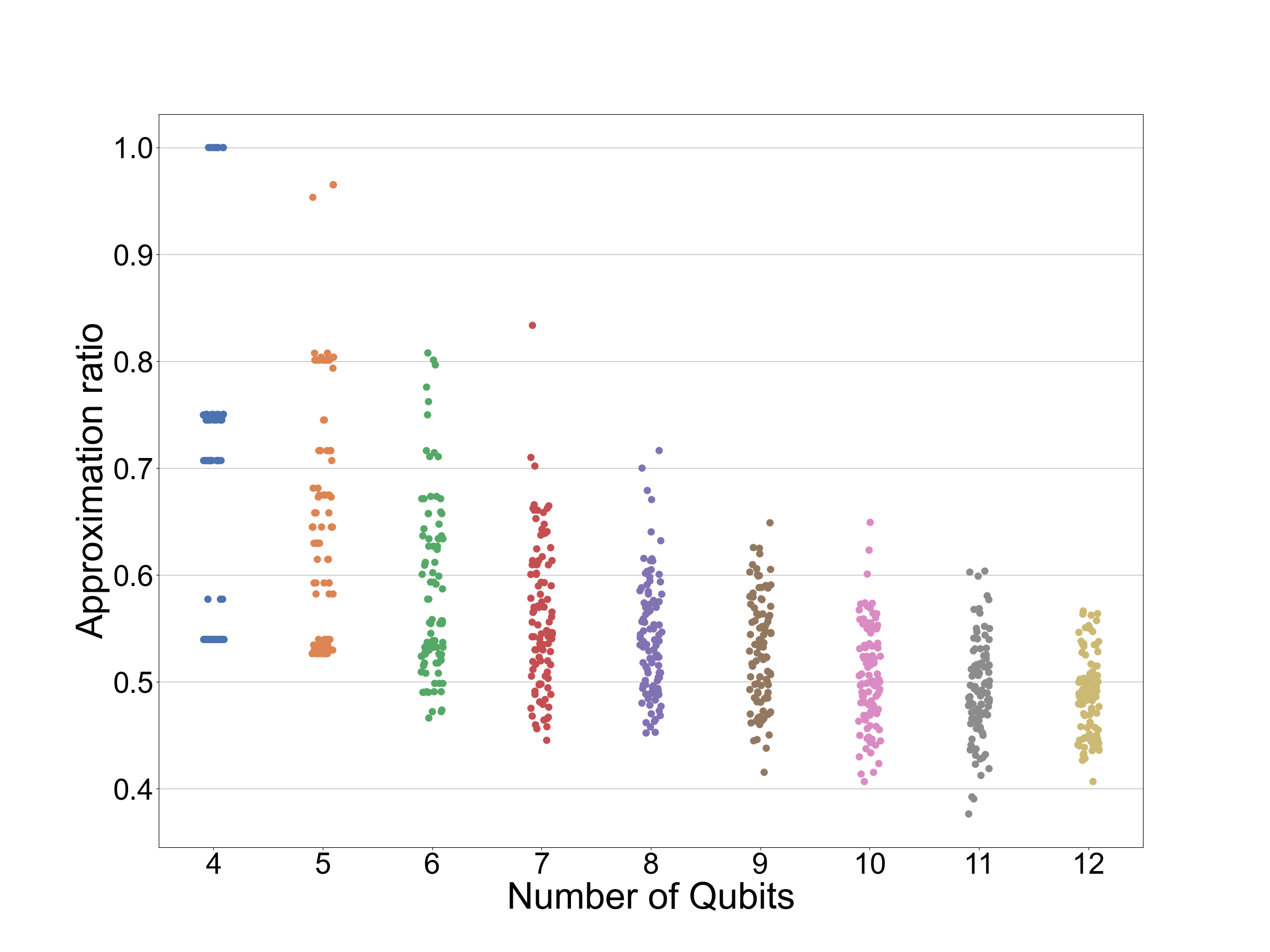
This work makes use of numerical experiments to establish the performance of new approaches. The results are often presented as a box-plot [81, 82]. The central line shows the median. The top and bottom line of the central box shows the lower and upper inter-quartile. Outliers are determined if they are more than 1.5 times more than the inter-quartile range away from the median and denoted by circles. The two caps at the end of the plot show the maximum and minimum data points, excluding outliers. Fig. 11 shows Fig. 5(a) in terms of the raw-data. The box-plot makes no assumption about the underlying distribution and provides a reasonable representation of the distribution for easy comparison.
As part of the numerics, we need to find the optimum time. For the new methods, this is found by a brute force grid search, dividing the optimal time into 1000 in the time-interval . For QAOA p=1, the grid was 100 by 100 in the interval and . By using brute force search we minimise the effect of the classical optimiser on the quantum algorithm.
Appendix E A further numerical study on a Sherrington-Kirkpatrick inspired model
To provide further evidence of the applicability of our approach in this section we repeat the numerical experiments performed on MAX-CUT on a Sherrington-Kirkpatrick inspired model (SKM). The details of the model can be found in Appendix B.
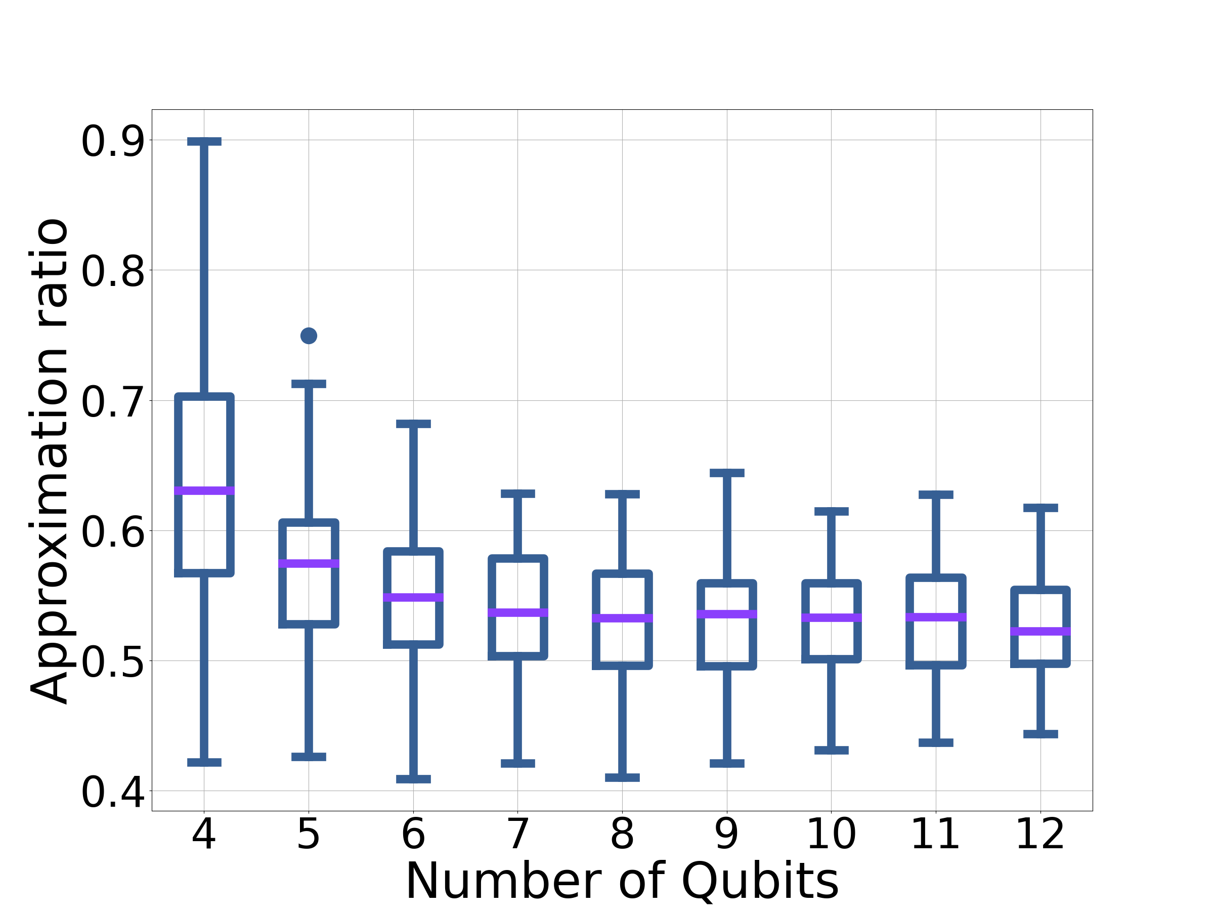
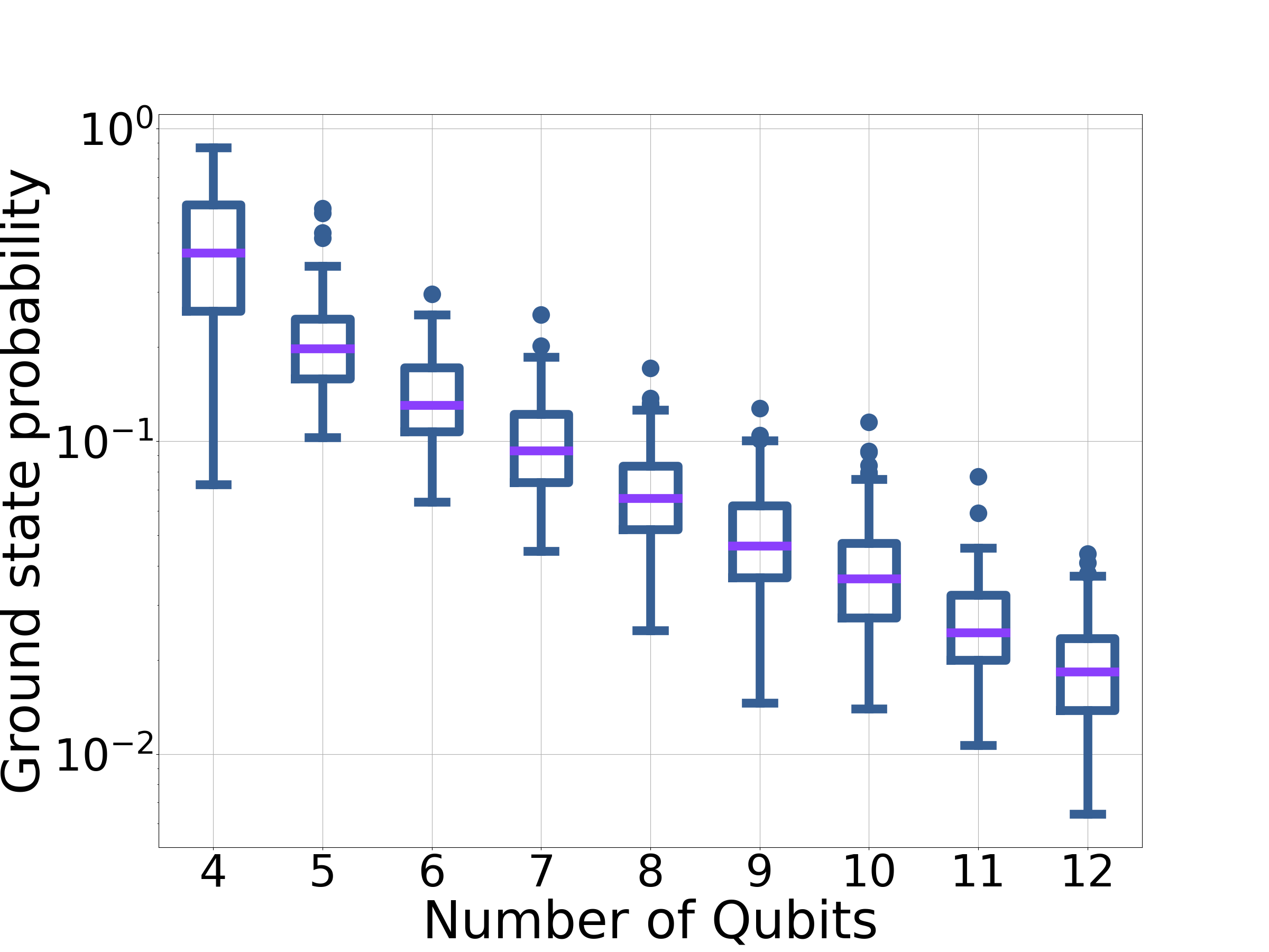
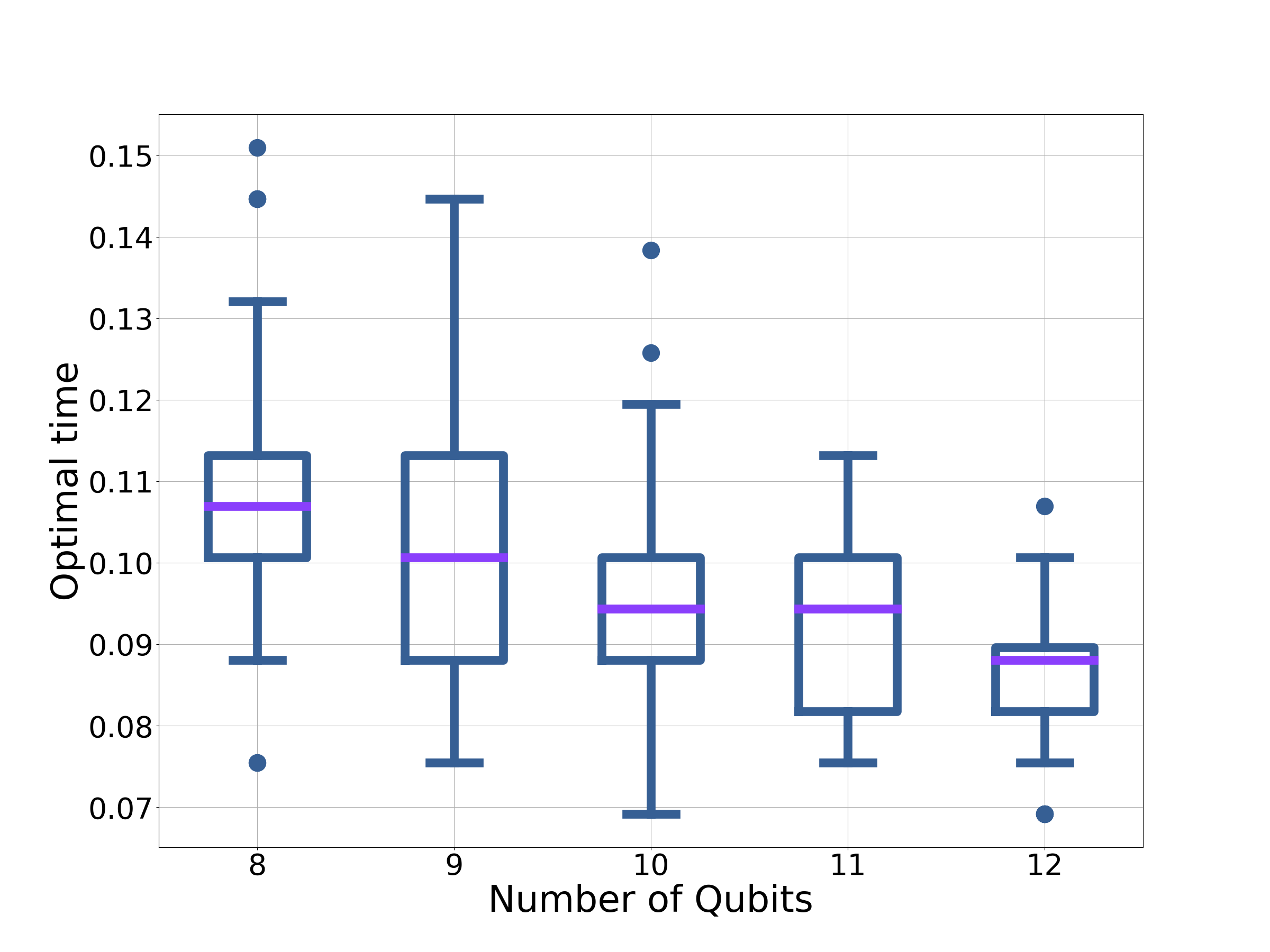
Starting with assessing the performance of , Fig. 12 shows the performance of on 100 randomly generated instances of the SKM. The approximation ratio appears to have little dependence on the problem size for more than 7 qubits, an indicator that the dynamics under is approximately local for these times. The ground-state probability also appears to decline exponentially (Fig. 12(b)). The optimal times can be found in Fig. 12(c). It appears that the optimal time tends to a constant value (or a small range of values), with .
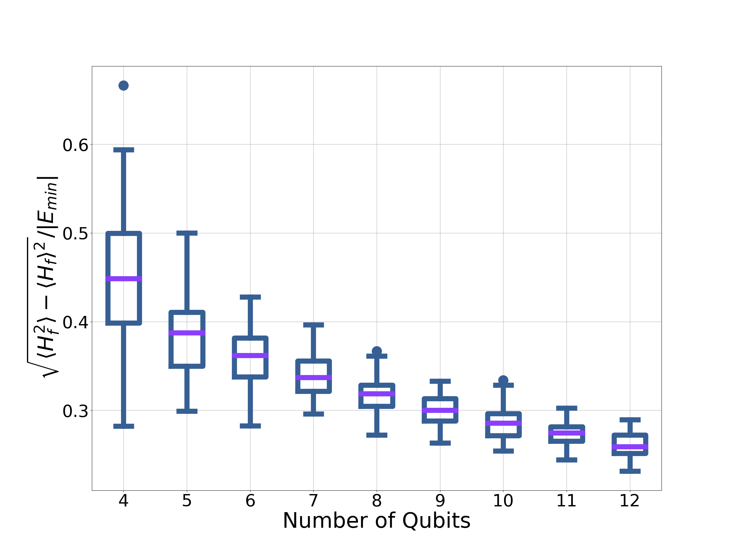
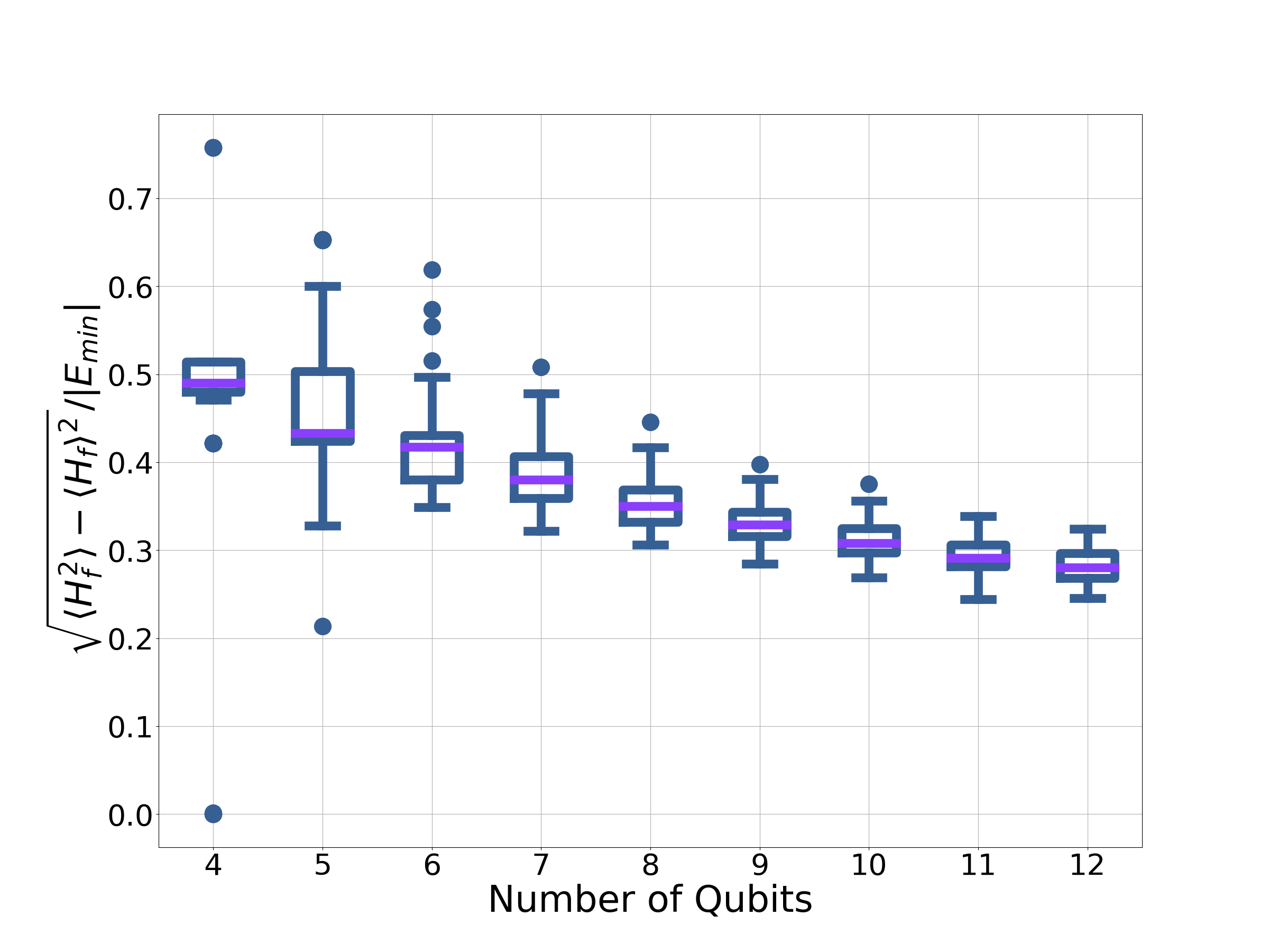
As mentioned in Appendix C, knowing the width of the distribution associated with the approximation ratio can also be useful. This is shown for SKM as well as the MAX-CUT instances on randomly generated graphs in Fig. 13. The width, is non-zero, suggesting the final state is not a computational basis state.
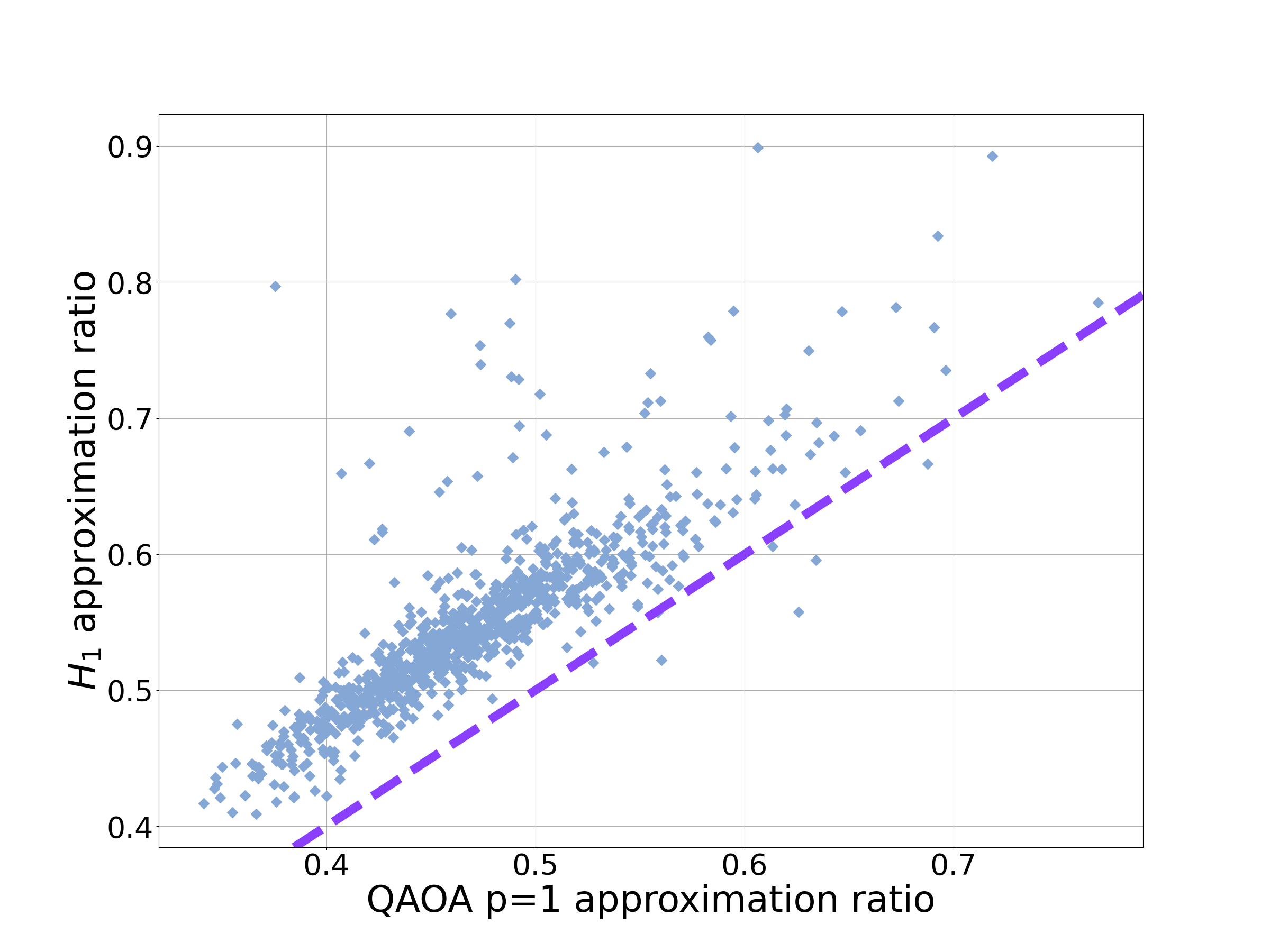
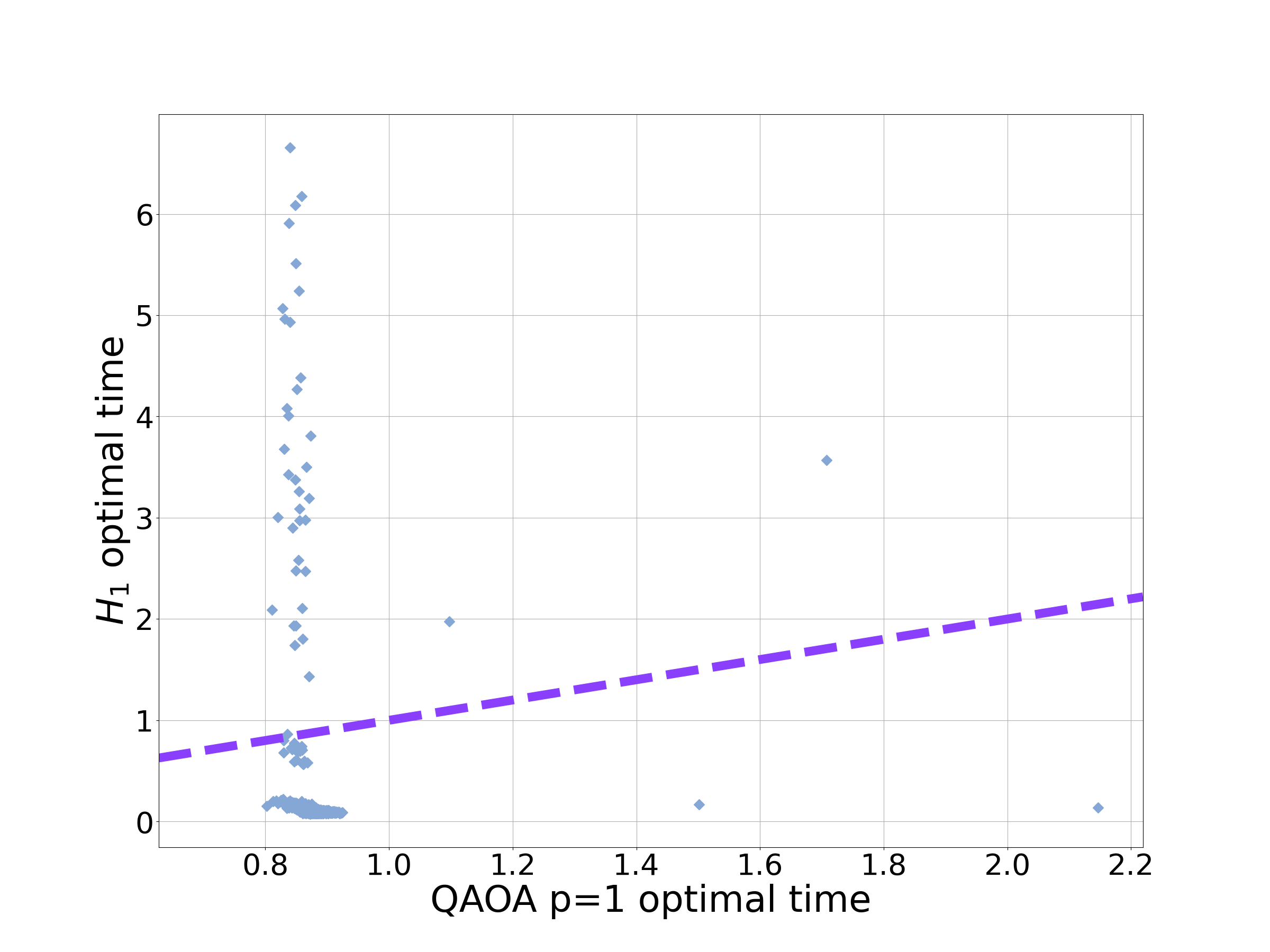
In Fig. 14 the performance of is directly compared to QAOA p=1 on 100 instances. For a handful of problems with the SKM, QAOA outperformed , but for the vast majority of problems instances performed better for both approximation ratio and optimal time. In Appendix J we elaborate further on the exceptions.
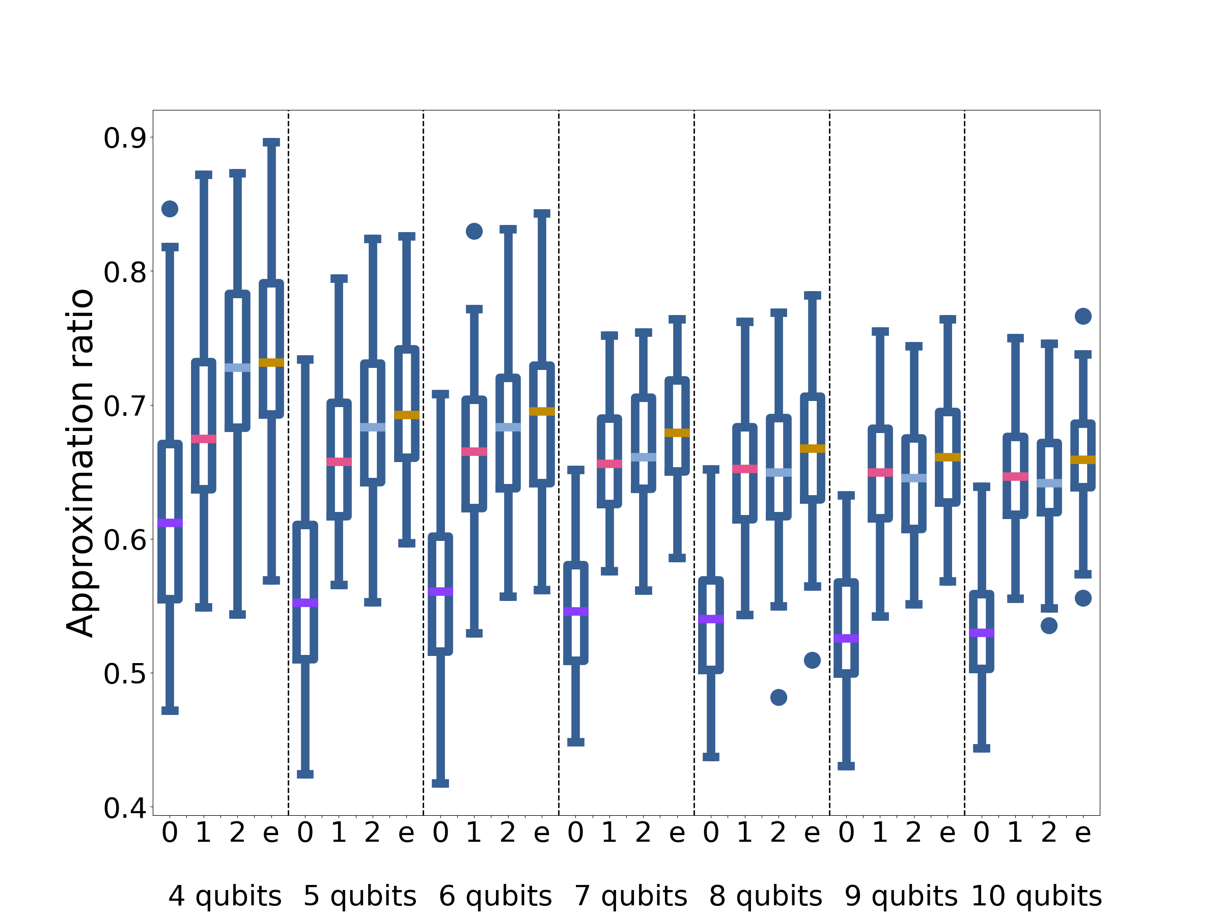
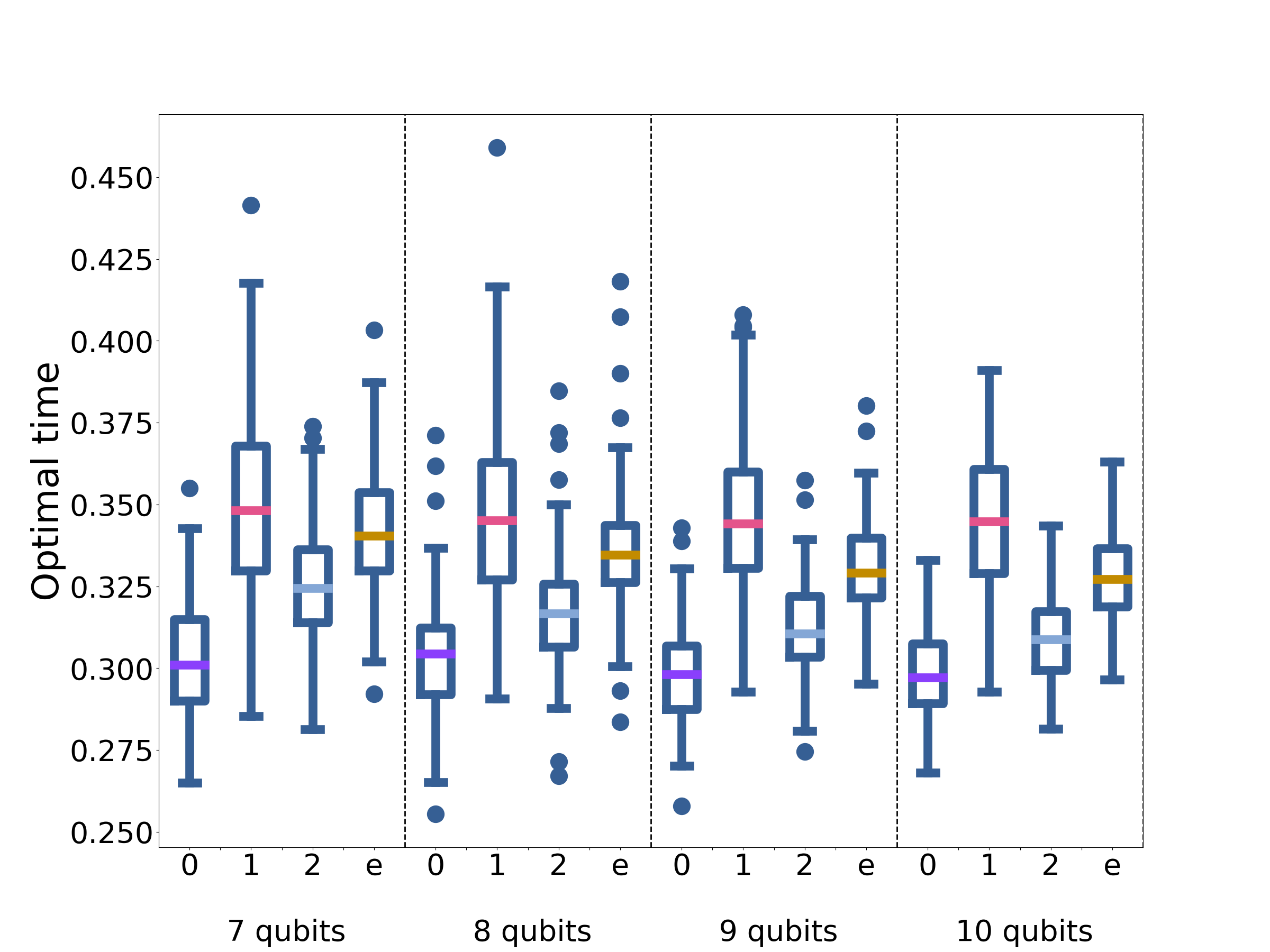
Finally, in Fig. 15 we assess the performance of the Quantum-Zermello inspired approach for 100 SKM instances. Again, all the QZ-inspired approaches provide an improvement on the original Hamiltonian, indexed by 0 in the figures. Going to first order achieves a substantial improvement as with the MAX-CUT instances. The optimal times for the QZ-inspired approach can be found in Fig. 15(b) for the SKM.
In this section we have demonstrated that the approaches inspired by Hamiltonians for optimal state-transfer operate qualitatively similar on SKM as they do on MAX-CUT.
Appendix F Optimal state-transfer for a single qubit
This appendix outlines the explicit details for calculating the Hamiltonian for optimal state-transfer for a single qubit. To simplify the calculations, we make use of index notation and the Einstein summation notation convention. For this reason, in this appendix the Pauli matrix is denoted by , with being the identity.
The first step is to construct traceless Hamiltonians with a trace-norm of one.
| (36) |
and
| (37) |
The Hamiltonians, and , have both the same eigenvectors, and ordering in terms of energy, as and . Expanding and in terms of Pauli matrices gives: and , where and, and are real vectors with Euclidean norm of one.
The eigenvectors of and correspond to and in the Bloch sphere representation. Ignoring the trivial case, when and are parallel, the two vectors define a plane. The vector is perpendicular to the plane an, generates rotations in the , plane. Note that:
where is the Levi-Civita tensor [83].
It is clear that generates a rotation in the plane spanned by and . This result also follows trivially from Eq. 2 for the single qubit case. The second step is to calculate the angle, , between the respective ground states (which is the same as the angle between the excited states). This can be deduced from the overlap between and :
Relating this angle to a time can be done by using the Anandan-Aharonov relation:
| (38) |
where . The Hamiltonian being considered is constant in time. Thus can be calculated using the initial state (i.e., ). Hence, we can deduce the time of evolution as:
| (39) |
Finally, the Hamiltonians, and , can be replaced by the original Hamiltonians. The time-optimal Hamiltonian for a single-qubit is:
| (40) |
The corresponding time is:
| (41) |
where is the uncertainty in energy corresponding to , and , are as defined earlier in this appendix.
It remains an open question as to how much of this geometric intuition in three dimensions can be mapped onto higher dimensional problems. Promisingly, the final operations (commutator, trace) are well defined outside of three dimensions.
Appendix G Mapping the evolution to free fermions for MAX-CUT on two-regular graphs
In this appendix we outline how to utilize the Jordan-Wigner transformation to analyse the performance of for MAX-CUT on two-regular graphs with qubits. The end goal is to map , , and onto fermionic operators. Applying a Fourier Transform then decouples the Hamiltonians into pseudo-spins that can be easily studied. The notation and method closely follows the calculation presented in [74].
The first step is to introduce spin-raising and -lowering operators:
| (42) | |||
| (43) |
In terms of these new operators:
| (44) | ||||
| (45) | ||||
| (46) |
The Jordan-Wigner transformation can now be applied to map these spin operators onto fermionic operators, and , where:
| (47) | ||||
| (48) |
and . The fermionic operators obey the standard anti-commutation relationship for fermionic operators (i.e., ). In terms of the fermionic operators the Hamiltonians are:
| (49) |
| (50) |
and
| (51) |
where . For even , (anti-periodic boundary conditions - ABC) and for odd , (periodic boundary conditions - PBC).
Apply a Fourier Transform with appropriate , such that for PBC and for ABC, such that,
| (52) |
The Hamiltonians in this new basis are:
| (53) |
| (54) |
and
| (55) |
where for odd :
and for even :
These Hamiltonians couple the vacuum state, , with doubly-excited states with opposite momentum, e.g., . Therefore, we can express the Hamiltonians as pseudo-spins,
| (56) |
with and:
| (57) | ||||
| (58) | ||||
| (59) |
with the exception of for , for odd n, which is half of the above expressions. The observation that generates rotations in the plane spanned by the eigenvectors of and provides further evidence that is capturing some of .
The initial state for each pseudo-spin is the ground-state of . Calculating the evolution for each pseudo-spin gives:
| (60) |
with for odd n, otherwise:
| (61) |
The ground state probability is given by:
| (62) |
again for odd n, otherwise:
| (63) |
This completes the analytical work used to analyse the performance of for MAX-CUT on two-regular graphs. It remains to find the optimal time to minimise - this was done numerically. Here we include the plots for an odd number of qubits (Fig. 16(a) and Fig. 16(b)).

Appendix H Lieb-Robinson inspired bound
In this section we outline how the Lieb-Robinson inspired bound (LRB) from [61] was applied to analysing the performance of on three-regular graphs.
First, we demonstrate how the bound was derived in [61]. The goal of this approach is to estimate the expectation value of a local observable by simulating part of the system. For this to be a useful estimate it is necessary to quantify the error in doing do, that is to calculate:
| (64) |
where is the initial state of the system, is the global unitary evolution of the system and the local unitary we wish to simulate. The error is bounded by
| (65) |
where is the matrix-norm. Adapting the proof from [61] for the case of evolution under a global time-independent Hamiltonian and local time-independent Hamiltonian gives:
Substitute in the Schrödinger equation for the time derivatives to get:
where . Tidying this up with gives:
| (66) |
Using the triangle-inequality,
This is essentially the expression (and proof) given in [61]. For Hamiltonians constant in time this can further be tidied up to:
| (67) |
The right-hand-side term in the commutator is a local operator depending only on the local system which we wish to simulate, while only includes terms in but not . Therefore, in the context of simulating qubits, the only terms in that do not commute through are the ones that couple qubits from the local system to qubits outside the system being simulated.
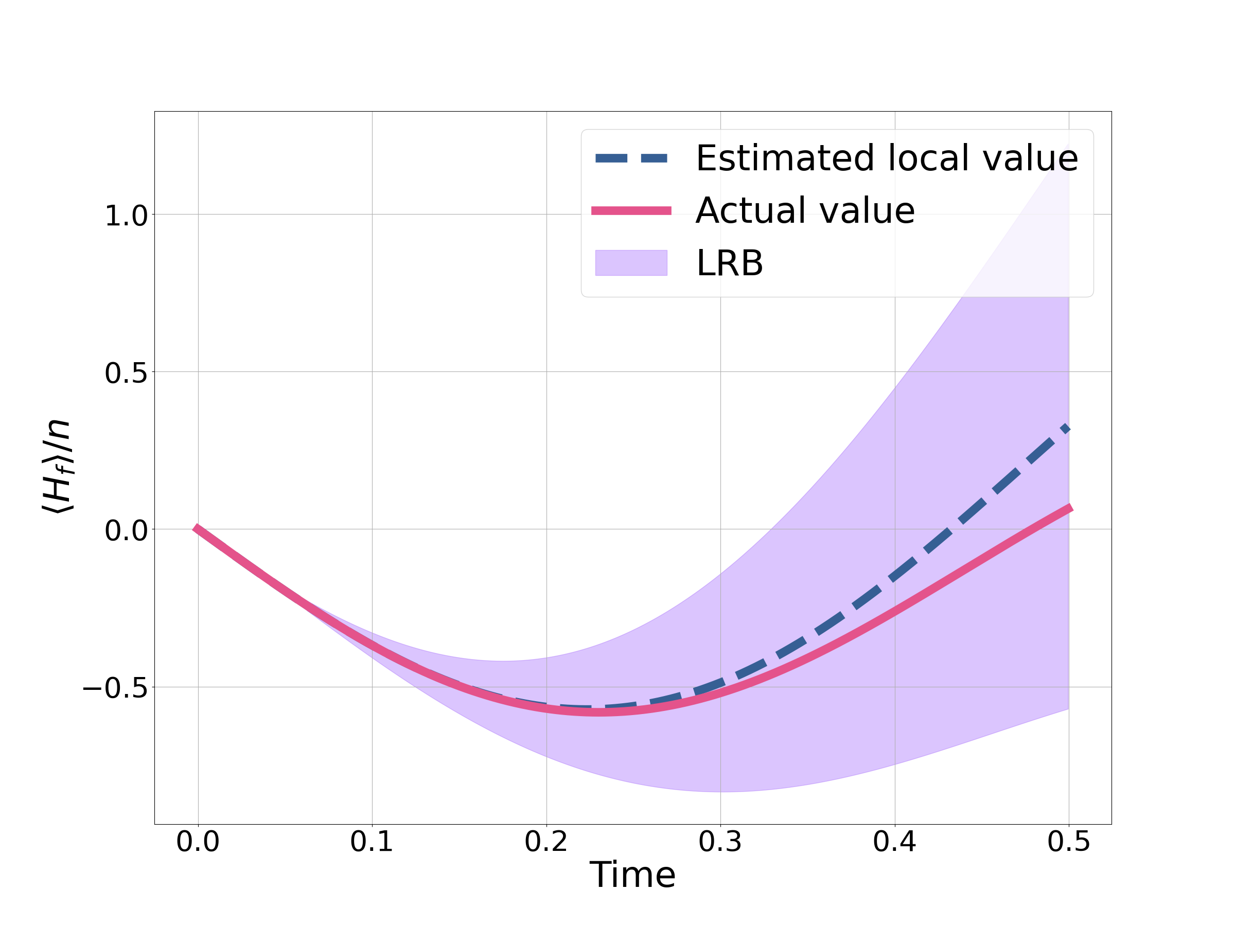
At this point it is useful to examine a simple system. Take MAX-CUT on two-regular graphs with . We wish to estimate , so we estimate the value by simulating the evolution under for the interactions between the pink qubits shown in Fig. 17. Choosing a larger subgraph should make the computation more accurate but will also result in a more difficult computation. Then using Eq. 67 we can calculate a bound on the error. Here corresponds to the interactions between the pink qubits and the blue qubits. Calculating the local estimate with LRB gives Fig. 18. The figure also shows the result for the MAX-CUT for a two-regular graph with 400 qubits.
The simulation shows that the bound is not very tight and, except at very short times, is not meaningful. It also demonstrates that behaves in a local fashion, with the full simulation (through the Jordan-Wigner transformation) closely matching the estimate from the local simulation. The LRB would be the lowest upper-bound shown in Fig. 18
Having established the idea behind the LRB, we now apply it to find the performance of on three-regular graphs. To do this we use
| (68) |
for the graph (or subgraph) being considered. The minimum value of is then mapped onto the length of the cut for easier comparison with QAOA and QA.
The performance of was determined by looking at the three local sub-graphs that can be found in [19, 61]. The error was calculated, taking the worst-case scenario, where each sub-graph has the maximum number of interactions exiting the sub-graph. Using the relative ratios of the sub-graphs [19], a worst case performance can be calculated. The numerical details can be found in Tab. 1.
| Subgraph 1 | Subgraph 2 | Subgraph 3 | |
|---|---|---|---|
| Local estimate of | -0.2056 | -0.2676 | -0.3377 |
| Upper estimate from LRB | -0.1333 | -0.1652 | -0.2007 |
| Cut value | 0.5666 | 0.5826 | 0.6003 |
Similarly to QAOA and QA [61], the LRB approach suggests that struggles the most with triangle-free graphs. The LRB, with local estimate, for the triangle-free subgraph can be seen in Fig. 19.
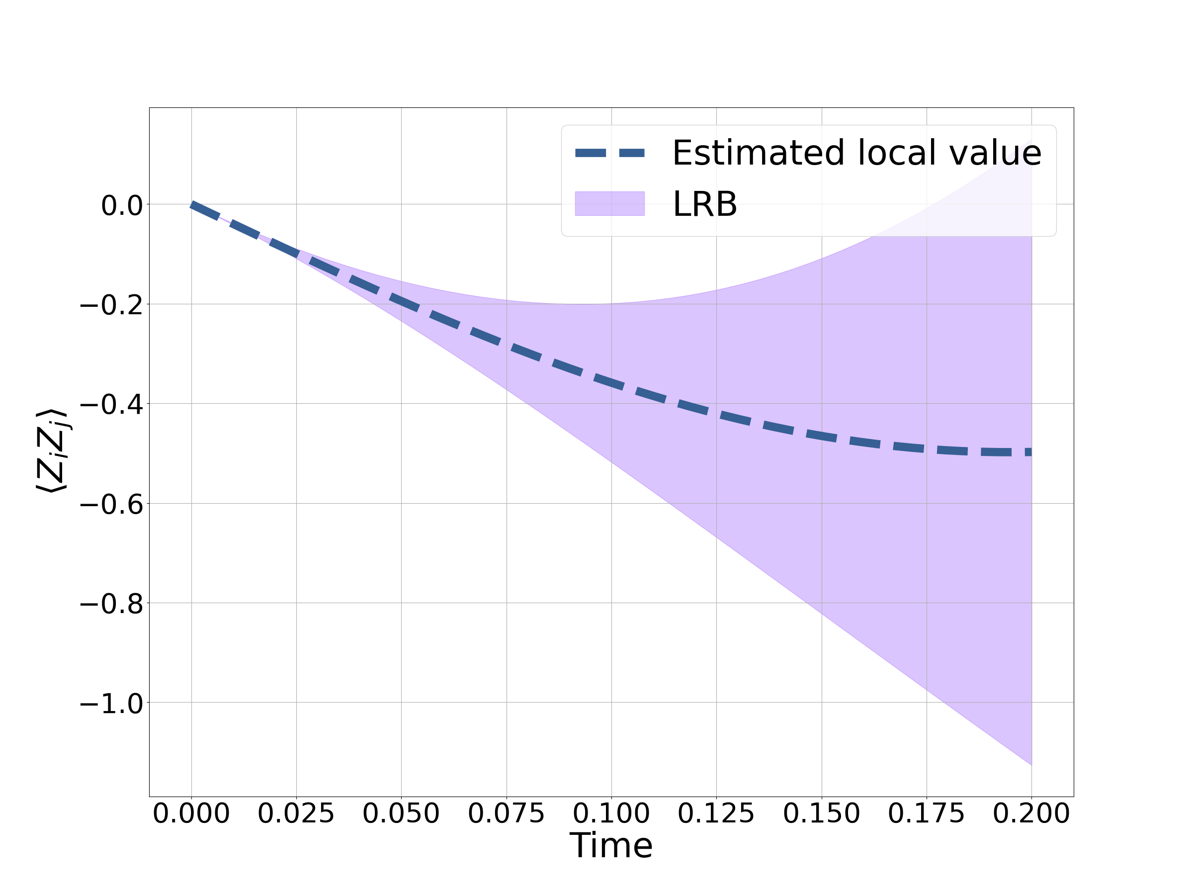
The LRB is taken at a time of 0.093, while the minimum for the local estimate occurs at around 0.2. Hence the LRB is sampling far from what is optimal for the local graph. Since we know the bound is not very tight, it is reasonable to assume that the worst-case performance of is actually better than the LRB and occurs at a later time (around ).
Appendix I Direct comparison of QAOA p=1 with three-regular graph
Appendix J Instances for which QAOA p=1 outperforms
| Graph 1 | Graph 2 | Graph 3 | Graph 4 |
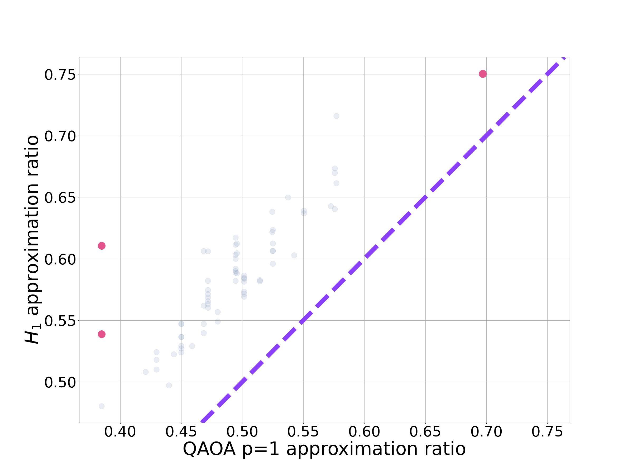
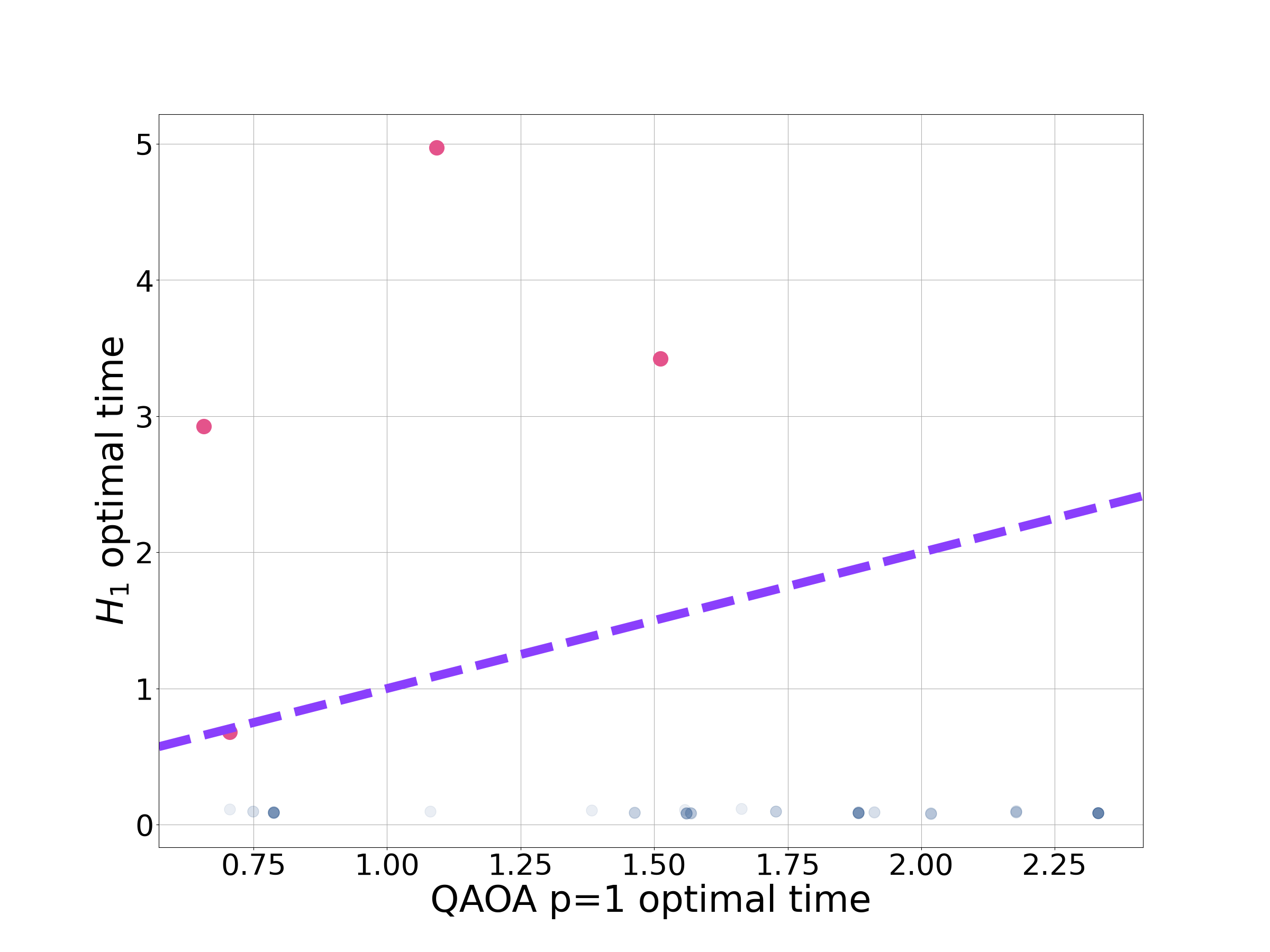
The aim of this section is to explore the instances where QAOA p=1 has a shorter run-time than and/or provides a better approximation ratio, as shown in Fig. 5. The first thing to note is that these tend to be the exception, rather than the rule.
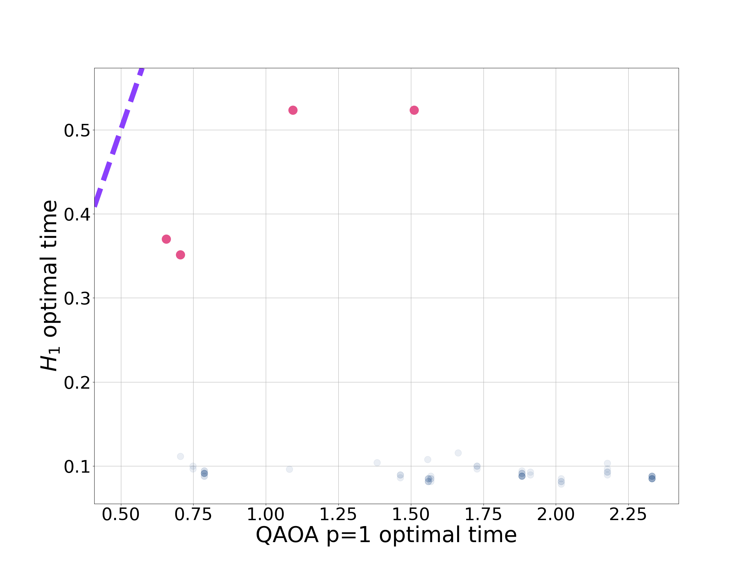
Looking first at the MAX-CUT instances for three-regular graphs, always provided a better approximation ratio than QAOA p=1, typically in a much shorter time. There are four instances (two with the same approximation ratio) where QAOA has a similar or shorter run-time as highlighted in Fig. 21. The corresponding graphs are shown in Tab. 2. The first thing to note is that these problems are small, the largest being 8 qubits, despite problem sizes up to 12 qubits being considered. Graph 1 is a complete graph with four nodes and Graph 4 is two copies of this graph. Both Graph 2 and 3 (a cube) consist of a large number of small loops. Due to the relatively high degree of connectivity in these problems, it is likely is no longer operating in the local regime as with the rest of the three-regular problems. In Fig. 22 we investigate operating suboptimally, optimising only over run-times shorter than QAOA p=1 for these four problems. The result is a negligible decrease in performance. Hence, even for these instances for which has atypical optimal times, it is possible for to provide a better approximation ratio in a shorter time than QAOA p=1.
As with the three-regular graphs, always gave a better approximation ratio than QAOA p=1 on MAX-CUT with the randomly generated graphs (highlighted in Fig. 23). Similarly, we can look at the instances with atypical optimal times for . The story is similar to before, with only 116 out of 900 instances having run-times longer than QAOA. None of these problem instances consisted of more than 7 qubits (despite simulations going up to 12 qubits). Again we conclude that these atypical optimal times are likely a small problem-setting phenomenon. We can also look for run-times of that provide a better approximation ratio in a shorter time than QAOA p=1 for these problems. The results are shown in Fig. 24 which shows the performance and new run-times of compared to QAOA p=1. For all problem instances it is possible to operate with a shorter run-time than QAOA p=1 and provide a better approximation ratio. Unlike the previous discussion with three-regular graphs, the change in approximation ratio with these new run-times is not negligible for some of the problem instances.
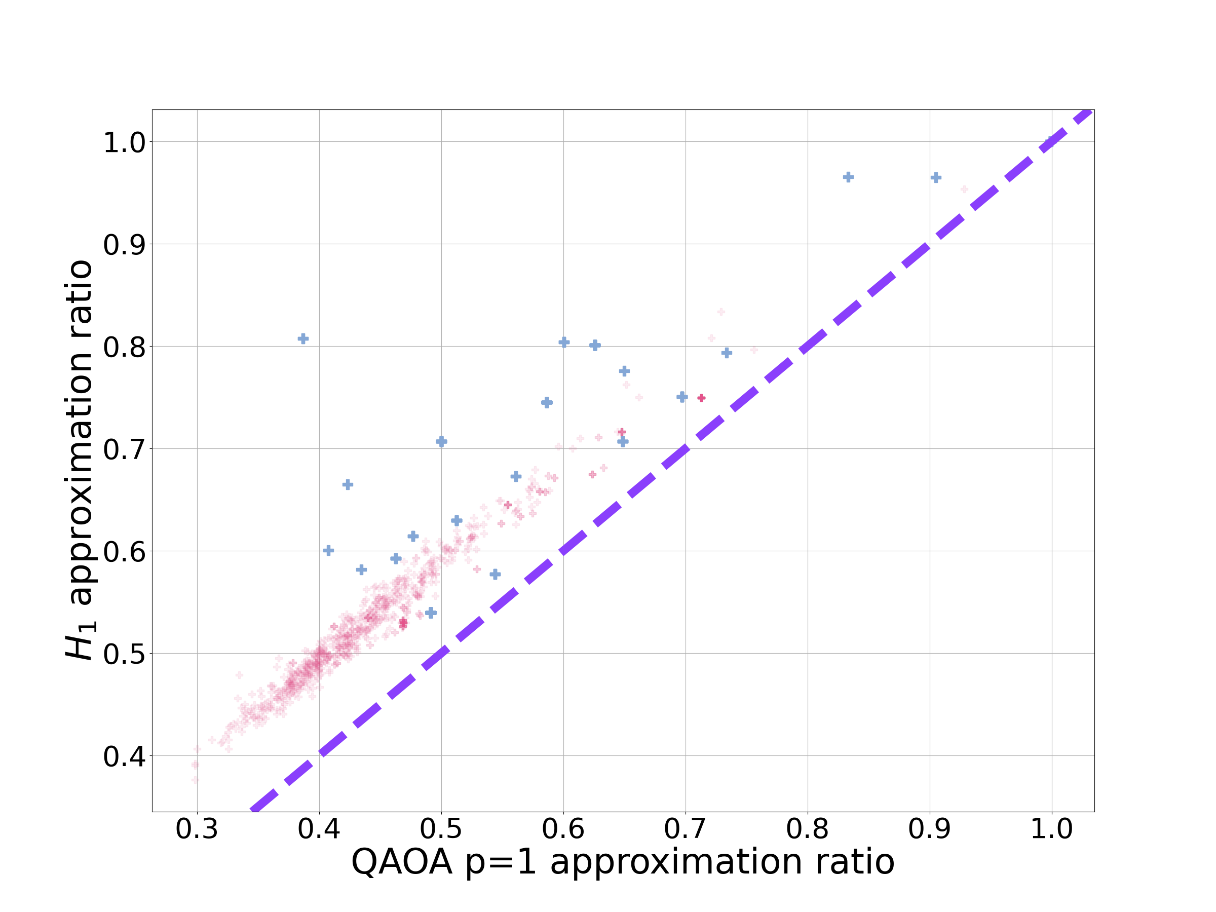
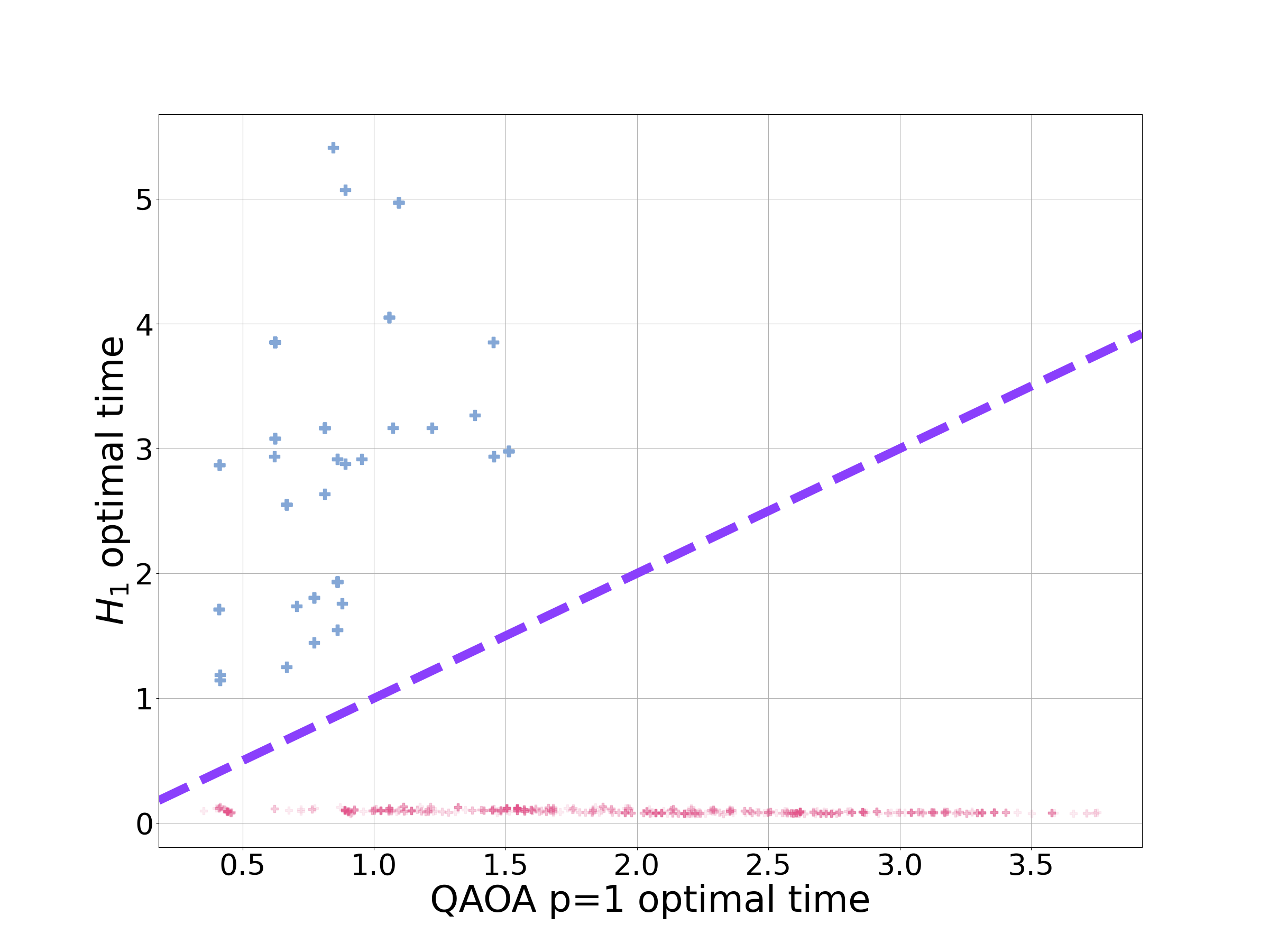

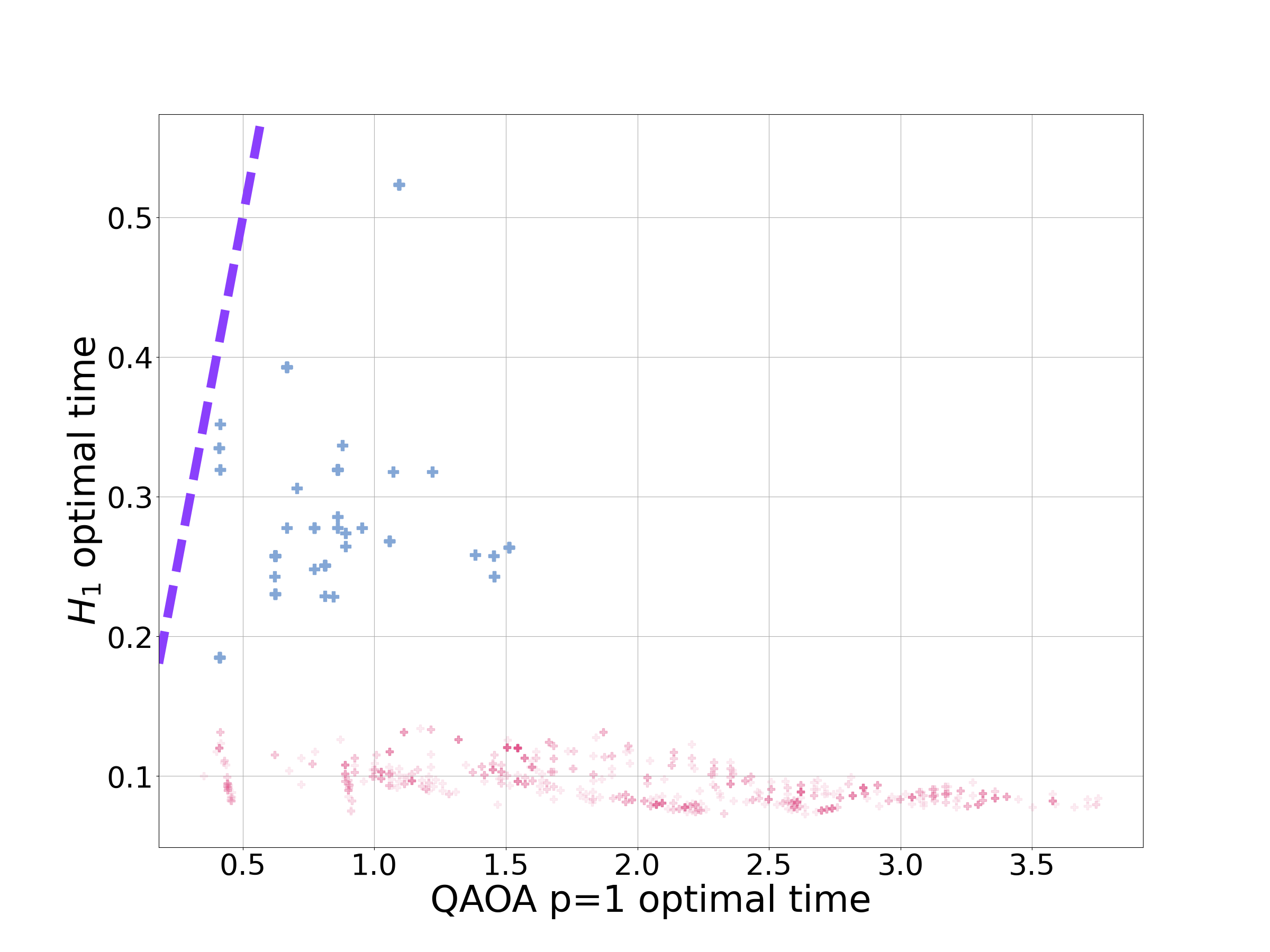
Finally, we turn to the SKM instances where QAOA p=1 was able to provide a better approximation ratio than for 7 problem instances (out of 900). Five of these instances are 4-qubit problems, the remaining two are 5-qubit problems. In Fig. 25 we have plotted the SKM data, including only those instances with problem sizes between 6 and 12 qubits. As we can see by ignoring small problem sizes from the data set, the behaviour is more predictable, with both the approximation ratio and the optimal time more clustered, largely independent of problem size.
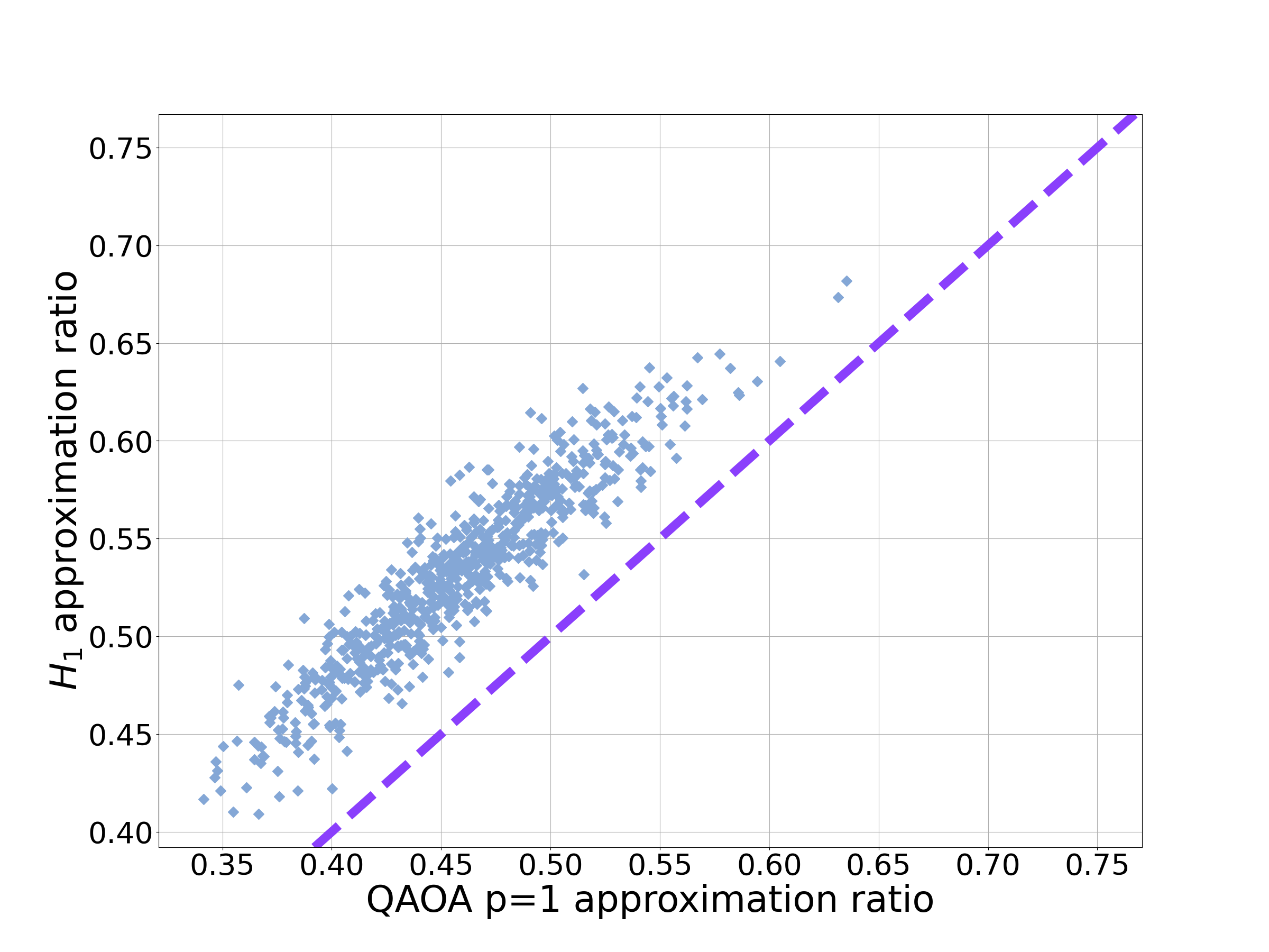
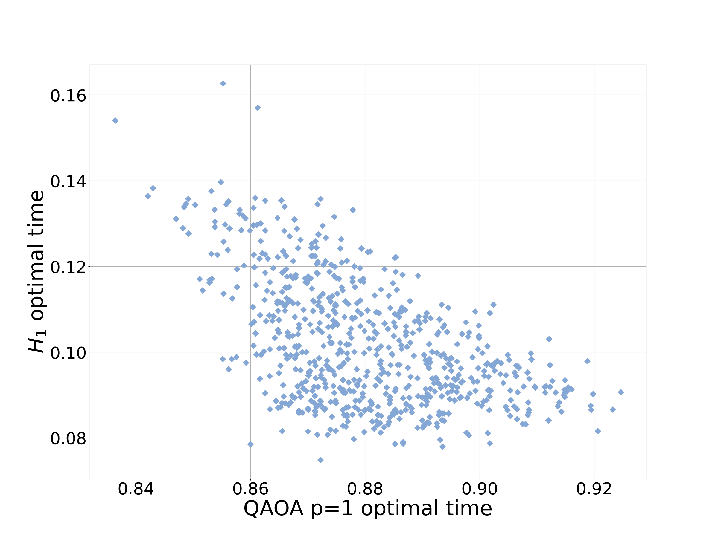
In summary, we have demonstrated numerically that QAOA p=1 might have some advantages over on small, highly connected problems. In general these problems are unlikely to be of any practical interest. Indeed for the MAX-CUT instances it was possible to operate suboptimally so that it still outperformed QAOA p=1 with a shorter run-time.
Appendix K Details for using knowledge of the initial state
In this appendix we provide the details for . First rewriting in terms of the eigenstates of , s with associated eigenenergies :
Let
| (69) |
Apply the Gram-Schmidt procedure to generate an orthonormal basis , spanning the same space as .
Rearranging for gives:
| (70) |
substituting this into gives:
| (71) |
where
| (72) |
Using the freedom in the global-phase of the wave-function, choose to be real, giving:
| (73) |
From Eq. 73 it is clear that evolves to linear superpositions of and . Again by using the Anandan-Aharonov relation, we can determine the time to generate and . Calculating :
The distance between and is
The distance between and is
The time then to evolve to is and the time to evolve to is .
We can explicitly verify this by exponentiating . Focusing on , then
This is a projector. Calculating gives:
Let be a Hamiltonian, where , being a projector. Then substituting into the power-series for the exponential gives:
Therefore,
| (74) |
and ,
| (75) |
Checking the times from the Anandan-Aharonov relationship gives:
and
Up to now we have kept the conversation in this section fairly general. Now we apply to the QA-framework with and s corresponding to computational basis states, so . Simplifying gives:
and the overlap with the initial state is:
To summarise, the Hamiltonian evolves to
| (76) |
in a time
| (77) |
where
| (78) |
