- PCI-E
- Peripheral Component Interconnect Express
- BMC
- Baseboard Management Controller
- I2C
- Inter-Integrated Circuit
- VRM
- Voltage Regulator Module
- PMBus
- Power Management Bus
- SMBus
- System Management Bus
- SVID
- Serial Voltage Identification
- KCS
- Keyboard Controller Style
- IPMI
- Intelligent Platform Management Interface
- 3DES
- Triple DES
- AES
- Advanced Encryption Standard
- ANF
- Algebraic Normal Form
- APB
- Advanced Peripheral Bus
- API
- Application Programming Interface
- ARX
- Addition, Rotate, XOR
- ASIC
- Application Specific Integrated Circuit
- ASK
- Amplitude-Shift Keying
- AXI
- Advanced Extensible Interface
- BCM
- Body Control Module
- BL
- Bootloader Enable
- BOR
- Brown-Out Reset
- BPSK
- Binary Phase Shift Keying
- CAN
- Controller Area Network
- CBC
- Cipher Block Chaining
- CBS
- Critical Bootloader Section
- CFG
- Control Flow Graph
- CGM
- Continuous Glucose Monitoring System
- CMOS
- Complementary Metal Oxide Semiconductor
- CMT
- Compare and Match Timer
- COPACOBANA
- Cost-Optimized Parallel Code Breaker and Analyzer
- CPA
- Correlation Power Analysis
- CPU
- Central Processing Unit
- CRC
- Cyclic Redundancy Check
- CRP
- Code Readout Protection
- CSTF
- CoreSight Trace Funnel
- CTR
- Counter (mode of operation)
- DC
- Direct Current
- DDS
- Digital Direct Synthesis
- DES
- Data Encryption Standard
- DFA
- Differential Fault Analysis
- DFT
- Discrete Fourier Transform
- DMA
- Direct Memory Access
- DoS
- Denial-of-Service
- DPA
- Differential Power Analysis
- DRAM
- Dynamic Random-Access Memory
- DRM
- Digital Rights Management
- DSO
- Digital Storage Oscilloscope
- DSP
- Digital Signal Processing
- DST
- Digital Signature Transponder
- DUT
- Device Under Test
- ECB
- Electronic Code Book
- ECC
- Elliptic Curve Cryptography
- ECU
- Electronic Control Unit
- EDE
- Encrypt-Decrypt-Encrypt (mode of operation)
- EEPROM
- Electrically Erasable Programmable Read-Only Memory
- ELF
- Executable and Linkable Format
- EM
- Electro-Magnetic
- ETF
- Embedded Trace Funnel
- ETR
- Embedded Trace Router
- FCC
- Federal Communications Commission
- FD
- Feedback Disassembly
- FFT
- Fast Fourier Transform
- FIR
- Finite Impulse Response
- FIVR
- Fully Integrated Voltage Regulator
- FPGA
- Field Programmable Gate Array
- FSK
- Frequency Shift Keying
- GCM
- Gateway Control Module
- GIAnT
- Generic Implementation ANalysis Toolkit
- GMSK
- Gaussian Minimum Shift Keying
- GPIO
- General Purpose I/O
- GPR
- General Purpose Register
- GPT
- General Purpose Timer
- HAL
- Hardware Abstraction Layer
- HDL
- Hardware Description Language
- HD
- Hamming Distance
- HF
- High Frequency
- HMAC
- Hash-based Message Authentication Code
- HW
- Hamming Weight
- I2C
- Inter-Integrated Circuit
- IC
- Instrument Cluster
- IC
- Integrated Circuit
- ID
- Identifier
- IIR
- Infinite Impulse Response
- IL
- Intermediate Language
- IoT
- Internet of Things
- IP
- Intellectual Property
- IRQ
- Interrupt Request
- IR
- Intermediate Representation
- ISA
- Instruction Set Architecture
- ISM
- Industrial, Scientific, and Medical (frequencies)
- ISR
- Interrupt Service Routine
- IV
- Initialization Vector
- JTAG
- Joint Test Action Group
- LCP
- Longest Common Prefix
- LFSR
- Linear Feedback Shift Register
- LF
- Low Frequency
- LQI
- Link Quality Indicator
- LSByte
- Least Significant Byte
- LSB
- Least Significant Bit
- LTE
- Long Term Evolution
- LUT
- Look-Up Table
- MAC
- Message Authentication Code
- MCU
- Microcontroller Unit
- MF
- Medium Frequency
- MITM
- Man-In-The-Middle
- MMIO
- Memory-mapped I/O
- MMU
- Memory Management Unit
- MSByte
- Most Significant Byte
- MSB
- Most Significant Bit
- MSK
- Minimum Shift Keying
- MSR
- Model Specific Register
- Microcontroller
- muC
- Microcontroller
- NAS
- Non-Access Stratum
- NFC
- Near Field Communication
- NLFSR
- Non-Linear Feedback Shift Register
- NLF
- Non-Linear Function
- NRZ
- Non-Return-to-Zero (encoding)
- NVM
- Non-Volatile Memory
- OCD
- On-Chip Debug
- OOK
- On-Off-Keying
- OP
- Operational Amplifier
- OS
- Operating System
- OTP
- One-Time Password
- PCB
- Printed Circuit Board
- PC
- Personal Computer
- PhD
- Patiently hoping for a Degree
- PKES
- Passive Keyless Entry and Start
- PKE
- Passive Keyless Entry
- PKI
- Public Key Infrastructure
- PMBus
- Power Management Bus
- PoC
- Proof-of-Concept
- POR
- Power-On Reset
- PPC
- Pulse Pause Coding
- PRNG
- Pseudo-Random Number Generator
- PSK
- Phase Shift Keying
- PTM
- Program Trace Module
- PWM
- Pulse Width Modulation
- RAPL
- Running Average Power Limit
- RDP
- Read-out Protection
- RE
- Reverse Engineering
- RFID
- Radio Frequency IDentification
- RF
- Radio Frequency
- RKE
- Remote Keyless Entry
- RNG
- Random Number Generator
- ROM
- Read Only Memory
- ROP
- Return-Oriented Programming
- RRC
- Radio Resource Control
- RSA
- Rivest Shamir and Adleman
- RSSI
- Received Signal Strength Indicator
- RTL
- Register Transfer Language
- RTOS
- Real-Time Operating System
- SCA
- Side-Channel Analysis
- SDR
- Software Defined Radio
- SDR
- Software-Defined Radio
- SGX
- Software Guard Extensions
- SHA-1
- Secure Hash Algorithm 1
- SHA-256
- Secure Hash Algorithm 2 (256-bit version)
- SHA
- Secure Hash Algorithm
- SHF
- Superhigh Frequency
- SMA
- SubMiniature version A (connector)
- SMBus
- System Management Bus
- SMT
- Satisfiability Modulo Theories
- SNR
- Signal to Noise Ratio
- SoC
- System on Chip
- SoC
- System-on-Chip
- SEV
- Secure Encrypted Virtualization
- SP
- Secure Processor (AMD)
- SPA
- Simple Power Analysis
- SPI
- Serial Peripheral Interface
- SPOF
- Single Point of Failure
- SUT
- System Under Test
- SVID
- Serial Voltage Identification
- SWD
- Serial Wire Debug
- TCB
- Trusted Computing Base
- TCU
- Telematics Control Unit
- TEE
- Trusted Execution Environment
- TMDTO
- Time-Memory-Data Tradeoff
- TMTO
- Time-Memory Tradeoff
- TPIU
- Trace Port Interface Unit
- TrustZone
- TrustZone
- UART
- Universal Asynchronous Receiver Transmitter
- UCODE
- Microcode
- UDS
- Unified Diagnostic Services
- UHF
- Ultra High Frequency
- UID
- Unique Identifier
- USB
- Universal Serial Bus
- USRP2
- Universal Software Radio Peripheral (version 2)
- USRP
- Universal Software Radio Peripheral
- VHDL
- VHSIC (Very High Speed Integrated Circuit) Hardware Description Language
- VHF
- Very High Frequency
- VLE
- variable length encoded
- VLF
- Very Low Frequency
- VR
- Voltage Regulator
- VXE
- Virtual Execution Environment
- WLAN
- Wireless Local Area Network
- XOR
- Exclusive OR
- VID
- Voltage Identifier
- OCP
- Over Current Protection
- Intel ME
- Intel Management Engine
PMFault: Faulting and Bricking Server CPUs through Management Interfaces
Abstract
Apart from the actual CPU, modern server motherboards contain other auxiliary components, for example voltage regulators for power management. Those are connected to the CPU and the separate Baseboard Management Controller (BMC) via the I2C-based PMBus. In this paper, using the case study of the widely used Supermicro X11SSL motherboard, we show how remotely exploitable software weaknesses in the BMC (or other processors with PMBus access) can be used to access the PMBus and then perform hardware-based fault injection attacks on the main CPU. The underlying weaknesses include insecure firmware encryption and signing mechanisms, a lack of authentication for the firmware upgrade process and the IPMI KCS control interface, as well as the motherboard design (with the PMBus connected to the BMC and SMBus by default). First, we show that undervolting through the PMBus allows breaking the integrity guarantees of SGX enclaves, bypassing Intel’s countermeasures against previous undervolting attacks like Plundervolt/V0ltPwn. Second, we experimentally show that overvolting outside the specified range has the potential of permanently damaging Intel Xeon CPUs, rendering the server inoperable. We assess the impact of our findings on other server motherboards made by Supermicro and ASRock. Our attacks, dubbed PMFault, can be carried out by a privileged software adversary and do not require physical access to the server motherboard or knowledge of the BMC login credentials. We responsibly disclosed the issues reported in this paper to Supermicro and discuss possible countermeasures at different levels. To the best of our knowledge, the 12th generation of Supermicro motherboards, which was designed before we reported PMFault to Supermicro, is not vulnerable.
keywords:
fault injection and software-based faults and Intel SGX and under/overvolting1 Introduction
In recent years, the security implications of software-exposed power and clock management features have received substantial attention by the research community. Several attacks including CLKSCREW [TSS17], Plundervolt [MOG+20], V0ltPwn [KFG+20], and VoltJockey [QWLQ19] showed that undervolting or overclocking from software can be used to inject faults (e.g., bitflips) into computations and break Trusted Execution Environments like Intel Software Guard Extensions (SGX) and ARM TrustZone. Subsequent attacks like VoltPillager [CVM+21] and the work by Buhren et al. [BJKS21] showed that similar attacks can be mounted with direct access to the computer hardware, physically connecting to the control interface of the Voltage Regulator (VR).
In particular, Chen et al.targeted the Serial Voltage Identification (SVID) interface used by Intel CPUs to set the desired supply voltage. However, apart from SVID, many systems, in particular servers, support a second interface, the so-called Power Management Bus (PMBus), to control the Voltage Regulator Module (VRM). PMBus is an open standard for digital power management [pmb] and has been adopted by more than 40 companies. It is based on the Inter-Integrated Circuit (I2C) bus and offers monitoring features apart from voltage and current control.
Another component usually presents on server motherboards is the Baseboard Management Controller (BMC). This chip, intended to remotely manage the server even if e.g., the main CPU has crashed or is powered down, has connections to several buses and chips on the motherboard, including the I2C bus on which the VRM resides.
Previous research on x86 platforms has focused on the software-hardware interface provided by the Central Processing Unit (CPU) itself and on the security within the perimeter of each individual component, e.g., the BMC [PGC18] or Intel Management Engine (Intel ME) [TW09, MIT17, GE17]. There is a lack of board-level security analysis that reviews the system and motherboard design and interactions between the different components: even if an individual part of the system is secure within its individual threat model, the combination of it with other parts can cause security risks. In our PMFault attacks, the privileged position of the BMC, combined with its large attack surface, makes it interesting from an adversary’s perspective to exploit vulnerabilities of the system via power management features.
1.1 Our Contribution
Our main contributions in this paper are:
PMBus-based under/overvolting against server platforms: We first analyse the VRM management interface at the hardware level. We discovered that the semi-standardised PMBus can be used to control the CPU voltage. Using the case study of a widely-used server motherboard, the Supermicro X11SSL-CF, we explore this attack surface and show that software vulnerabilities in the BMC (or another programmable chip connected to the PMBus) can have severe consequences for the security and safety of the server platform. To determine if the vulnerabilities can affect other server motherboards, we also investigated the PMBus connections and usage on an ASRock E3C246D4I-2T and a Supermicro X12DPi-NT6.
PMBus access through BMC exploits: We then study the BMC firmware and—based on prior work in [Ecl18, Rak15, Nie20]—found that it can indeed be exploited to send arbitrary PMBus commands to control the voltage of the CPU. More precisely, several software vulnerabilities in the BMC, including incorrect firmware encryption and signing mechanisms, a lack of authentication for firmware upgrades and control interfaces, an attacker can manipulate the CPU voltage remotely because the PMBus is connected to the BMC and the System Management Bus (SMBus) by default.
PMBus-based undervolting against SGX enclaves: With this, we observed the same faults as with Plundervolt/V0ltPwn (CVE-2019-11157), including for code running inside an SGX enclave. As the BMC has an independent, external flash chip for its firmware, SGX attestation currently does not have the ability to verify its status. Crucially, because the software voltage-control interface in Model Specific Register (MSR) 0x150 is not used, Intel’s fix for CVE-2019-11157 does not address this attack.
Permanent denial-of-service through overvolting: We also discovered a novel overvolting attack: by sending a certain sequence of PMBus commands, we can set the CPU voltage outside the specification (as high as 2.84 V) and permanently brick the Xeon CPU used in our experiments.
Countermeasures and mitigations: Finally, we develop the PMBusDetect tool for detecting if the VRM is connected to the PMBus, and then discuss countermeasures and challenges in securing server platforms. Importantly, we point out that TEEs like SGX must not only rely on the security of the CPU itself, but also of that of management components the hardware design of the platform.
The details of our experiments and source code can be found at: https://github.com/zt-chen/PMFault. CVE number CVE-2022-43309 has been reserved for PMFault.
1.2 Adversary Model
In this paper, we assume a privileged software attacker, i.e., who has obtained root on the host CPU. This is the standard adversary model in the case of TEEs like SGX, and is also realistic in the case of overvolting to permanently destroy the CPU, which could be e.g., exploited by ransomware with root rights. Notably, our attacks do not require physical access (for additional hardware to be added to the system) and can thus be conducted remotely e.g., over SSH.
1.3 Responsible Disclosure
We have responsibly disclosed our findings to Intel and Supermicro in April 2022. We discussed the details of our methods in several calls with Supermicro, and they acknowledge the existence of the issue and are looking into deploying fixes for their 11th generation products like the Supermicro X11SSL-CF. Supermicro highlighted that the attacks do not replicate on their 12th generation, which e.g., include secure boot and update for the BMC and filtering on PMBus commands. Both of these features break the attack chains described in the paper. Intel considered the issue in the context of their own server motherboards and did not find them vulnerable. Intel did not comment on the impact on SGX.
1.4 Related Work
Since Boneh et al.’s seminal work on fault injection [BDL97], the research community has devoted substantial efforts to investigating fault attacks and developing according countermeasures (cf. e.g., [BECN+06] for an overview).
Software-based Fault Injection
Often, fault injection was considered a technique limited to attacks with physical access to the target. However, with the discovery of the Rowhammer effect [KDK+14], it was shown that faults can also be injected from software (through specific memory access patterns in the case of Rowhammer). Then, in 2017, Tang et al.showed that the clock management features of ARM processors can be exploited to inject faults into computations shielded inside a TEE like ARM TrustZone [TSS17]. Similarly, Plundervolt, V0ltPwn, and VoltJockey [MOG+20, KFG+20, QWLQ19] (all tracked via CVE-2019-11157) use the software-exposed voltage control MSR in Intel processors to break the integrity guarantees of SGX enclaves. In response, Intel deployed a microcode update that disables the undervolting interface in MSR 0x150 and allows remote parties to verify correct configuration through SGX’s remote attestation. Thus, purely software-based undervolting attacks against Intel processors were considered no longer possible.
Hardware-based Fault Injection on TEEs
The second generation of undervolting attacks on TEEs like SGX and AMD Secure Encrypted Virtualization (SEV) require physical access to the target motherboard. In the case of VoltPillager [CVM+21], the adversary attaches two wires to the data and clock lines of the SVID bus and can then control the VRM external to the CPU, enabling undervolting even if Intel’s microcode fixes for CVE-2019-11157 are installed. For AMD SEV, the adversary does not glitch the actual CPU, but the separate security co-processor, the AMD Secure Processor (SP) [BJKS21]. The adversary then proceeds to upload custom firmware to the SP to leak memory encryption keys and also endorsement secrets, which ultimately enable attacks without permanent physical access.
Security of servers and BMCs
Independent of hardware-based attacks, the security of server platforms has received attention in the research community and wider society. In 2018, Bloomberg published a—since widely disproven—article that incorrectly claimed the inclusion of small backdoor chips on Supermicro motherboards [RR18]. However, at the same time, researchers at Eclypsium showed that it is indeed possible to maliciously manipulate the BMC firmware of Supermicro motherboards from 8th to 11th generation [Ecl18], without the need to add a hardware implant. They also demonstrated how flashing corrupted BMC firmware can “brick” the server system by preventing it to boot.
Niewöhner [Nie20] subsequently published a tool to exploit the (weak) firmware encryption of Supermicro BMCs. Other work, for example by Waisman et al. [WS18] and Périgaud et al. [PGC18], has shown that software weaknesses in BMCs are not limited to Supermicro motherboards, but also applied to Dell, HP, and Lenovo systems.
1.5 Paper Outline
The remainder of this paper is structured as follows: in Section 2, we review the PMBus protocol and analyse its specific implementation and usage on Supermicro motherboards. Then, in Section 3, we describe Supermicro’s BMC implementation and methods to modify the firmware. In Section 4, we experimentally investigate how a compromised BMC can interact with the VRM through the PMBus. We then use this to develop over/undervolting attacks in Section 5, before concluding in Section 7.
2 Analysis of Power Management Bus
We started our work by analysing how the PMBus is used on practical server motherboards. PMBus is an interface that is used to control the VRM, supplying the power to the CPU. The most recent public available specification is version 1.3 [pmb]. This specification standardises the physical interface, packet structure, and command set of the PMBus. However, some commands are left as “manufacturer specified”, so that each VRM manufacturer can have a slightly different implementation of the command set. This matches what we found during our investigation of the MP2955 VRM on the Supermicro X11SSL-CF platform described in the following.
2.1 Experimental Setup
We carried out initial experiments with an Intel Xeon E3-1220 v6 (CPU family: 6, model: 158, microcode version: 0xea) on a Supermicro X11SSL-CF Rev 1.01 motherboard (BMC microcontroller ASPEED AST2400, firmware revision 01.63, BIOS version: 2.4).We used 64-bit Ubuntu 18.04.3 LTS with a stock 5.4.0-107-generic kernel, Intel SGX driver V2.11.0, and Intel SGX-SDK V2.15.100.3. We refer to this system as E3-1220V6-X11SSL-CF throughout the paper. An overview of the server motherboard representative for Supermicro’s 11th generation products is shown in Figure 1. The target of the PMFault attack is an Intel CPU with SGX technology. As mentioned, our actual attacks do not require additional hardware or physical access to the system, though we soldered some wires to the motherboard during the analysis phase.
On Intel platforms, the voltage of the CPU is controlled by an external VRM Integrated Circuit (IC). The CPU connects to the VRM via the SVID bus to control the voltage supplied by it. This interface for CPU voltage control is present on all desktop and server motherboards.
However, server VRMs—including the Supermicro X11SSL-CF—often have an additional I2C-based communication interface called PMBus. This interface allows e.g., overclocking or fine-tuning of the CPU voltage. One of the crucial steps in the PMFault is to get access to this interface and understand the communication protocol, so that we gain full control of the CPU voltage.
One of the design issues we found on our server motherboard is that the PMBus can be directly connected to the more general SMBus. There are various components on the system on that bus, including the CPU, BMC, and other I2C devices. A compromise of any of these components leads to the takeover of PMBus and thus control of the CPU voltage.
In this paper, we use the BMC as the starting point of the attack, as it commonly exists on server platforms. In order to analyse the attack surface of the BMC, we further investigated its connection and hardware design on the Supermicro X11SSL-CF. First, we found that its firmware is stored in a Serial Peripheral Interface (SPI) flash chip, separate from the BIOS flash. We also found there are two Ethernet ports on the system for communication with the BMC: one is called “Management Ethernet” and is dedicated for server management. The other port can be shared between CPU and BMC so that devices on this Ethernet port can communicate with both CPU and BMC. Finally, the BMC also has a Keyboard Controller Style (KCS) interface that enables direct access from the Operating System (OS) running on the CPU. These management interfaces open a large attack surface on the BMC, and make remote attacks possible.
2.2 Protocol Structure
To be able to eavesdrop and forge PMBus commands, knowledge of the protocol structure shown in Figure 2 is necessary. The PMBus is an I2C-based protocol (with clock speed of 100 kHz–1 MHz and an open-drain data pin) and uses a master-slave communication mechanism. The master device can query or change the setting of the slave device. Each slave device is assigned a unique 7-bit device address.
The master device first sends a starting bit to initiate a transmission. During transmission, every group of 9 bits forms a segment, with the 9th bit indicating ACK (0) or NACK (1) for every 8 bits received. The starting bit and the (N)ACK mechanism are handled at hardware level and do not need to be handled manually.
The first segment is always sent by the master. The first 7 bits are the address of the target slave, and the 8th bit indicates whether this transmission is a read (1) or write (0). The second segment is the register address to operate on. In the PMBus specification, this segment is called the PMBus command. The segments after the second one contain the data read from or written to the register.
Interaction between PMBus and SVID
Although the functionality of the PMBus protocol is similar to SVID, they have different specifications for the digital signal interface and command sets. A VRM can have both SVID and PMBus interfaces, with the SVID interface directly connected to the CPU and the PMBus interface connected to the SMBus. Both interfaces can be used to control the voltage of the CPU, and some implementations of the PMBus specification also have commands to override the voltages set through the SVID interface.
2.3 PMBus Commands
For an adversary to communicate with the VRM and e.g., configure voltage levels, they also need to know the specific PMBus commands. As mentioned, the PMBus specification allows manufacturers to have custom implementations of PMBus commands. The E3-1220V6-X11SSL-CF motherboard features an Monolithic Power MP2955 voltage regulator. To understand the PMBus implementation of this VRM, we first started looking for its datasheet, but unfortunately, found that it is not publicly available. However, on the Monolithic Power website111https://www.monolithicpower.com/, we found the datasheet of an alternative VRM (MP2965) [Mon]. As both chips are manufactured by the same company, we used this datasheet as a reference and starting point to discover the available PMBus commands by analysing the PMBus traffic on the Supermicro X11SSL-CF.
We found the relevant PMBus commands by reading and analysing the response (ACK or NACK) of the registers, and validating found commands according to the PMBus specification and the MP2965 datasheet : Table 1 gives the command name, command code, and description of each commands. The first three commands in the table are implemented according to the PMBus 1.3 specification [pmb], while the rest are manufacturer-specific.
| Command name | Command code | Usage |
|---|---|---|
| CMD_PAGE | 0x00 | Switch between different voltage rails |
| CMD_OPERATION | 0x01 | PMBus override |
| VOUT_COMMAND | 0x21 | Output voltage settings |
| READ_VOUT | 0x8B | Voltage reading from sensor |
| MFR_VR_CONFIG | 0xE4 | Enable overclock mode |
| MFR_OCP_TOTAL_SET | 0xEE | Over-current protection configuration |
With CMD_OPERATION, we can configure the operation mode of the VRM. By setting bit 1 of this register, we can enable the PMBus override mode. In this mode, the voltage configured in the VOUT_COMMAND register will override the voltage configuration from the SVID bus. Another command that is useful for PMFault is READ_VOUT, as it allows us to read the current voltage of the CPU and establish a baseline for undervolting. The MFR_VR_CONFIG register is manufacturer-specific. By setting bit 3 or bit 10 and configuring CMD_OPERATION, we could enable the tracking or fixed voltage overclocking mode, respectively. Bit 8 VID_STEP_SEL of MFR_VR_CONFIG also allow us to use an alternative mode of SVID. In this mode, the VRM uses 10 mV Voltage Identifier (VID) steps instead of the default of 5 mV. This makes overvolting up to 3 V possible, which is well beyond the operating voltage range of the E3-1220 V6 Intel CPU, with a maximum voltage of 1.52 V [Cor18]. We also discovered that the VRM has an Over Current Protection (OCP) circuit, which can be configured or disabled by another manufacturer-specific register (MFR_OCP_TOTAL_SET). Some VRM also support multiple voltage output rails. CMD_PAGE command is used to select the target rail to send the commands to.
With these discovered commands, we can now control the CPU voltage through the PMBus. In Section 4.1, we detail how this interface is used as part of attack chains for undervolting and overvolting attacks.
2.4 Jumper Settings
On the Supermicro X11SSL-CF motherboard, there are several jumpers that control different functionalities, including the connection of the VRM to other parts of the system. We kept all jumpers in the default status as delivered by the vendor. To avoid confusion, we still list the jumper settings in Table 2. During inspection of the jumper settings, we discovered that the SMBDAT_VRM and SMBCLK_VRM jumpers are neither mentioned in the user manual [Supb] nor in the quick reference guide [Supa]. Using an oscilloscope while sending PMBus commands, we found that these two jumpers can be used for (dis)connecting the VRM from/to the PMBus. The experiments and attacks described in this paper are conducted under the “connected” setting of both jumpers, which according to Supermicro is the default.
We also found server motherboard without such jumpers, e.g., Supermicro X11SPG-TF and ASRock E3C246D4I-2T. For those, the VRM is always connected to the BMC. We detail our finding on other motherboards in Section 6. It is worth mentioning that to the best of our knowledge, SGX attestation does not have the functionality to include the configuration of these (external) jumpers.
3 Supermicro’s BMC and Server Management Interface
Having understood the basic PMBus protocol and commands, we next look at different ways to gain access to the PMBus and send commands to the VRM. To achieve that, an attacker needs access to the SMBus. As described in Section 2.1, on E3-1220V6-X11SSL-CF, one of the devices on the SMBus is the ASPEED AST2400 BMC controller. In this section, we introduce the functionalities and vulnerabilities in these management interfaces that allow us to achieve our main goal—to take control of the SMBus.
During the initial investigation of the BMC, we found there are mainly three services available: there is a web service running on port 80 (HTTP) and 443 (HTTPS), an Intelligent Platform Management Interface (IPMI) over LAN service on port 623, and the SSH service on port 22. Besides, we also found that the IPMI service can be accessed through the KCS interface from the CPU.
Some of these interfaces require authentication: to use HTTP, HTTPS, SSH, and IPMI -over-LAN, all exposed through Ethernet, one has to authenticate to the BMC. The used credentials in this authentication process are individual for each Supermicro motherboard. However, the IPMI-over-KCS interface does not require any authentication to the BMC. Instead, having root privileges on the host OS running on the CPU is sufficient to access this interface. One can also use the IPMI-over-KCS interface to add/remove/modify BMC credentials to subsequently login to the Ethernet-exposed interfaces.
3.1 SSH Shell
Since SSH is one of the most common interfaces that allows us to get a shell and possibly take over the system, we first started our investigation with it. However, the SSH service on E3-1220V6-X11SSL-CF provides a custom shell called “ATEN SMASH-CLP System Management Shell”. It only provides limited commands that enable server monitoring and basic management. Previously, a vulnerability was reported in [Vaz13]: the command shell sh allows gaining root access from this shell, however, this command was not available on our system-under-investigation.
3.2 BMC Firmware Analysis
To further investigate the services running on the BMC and check if it is possible to enable an SSH root shell, we dumped the firmware of the BMC with a CH341A SPI flash programmer as shown in Figure 3. This procedure is only used once to assist our analysis, and is not necessary to execute the actual attack.
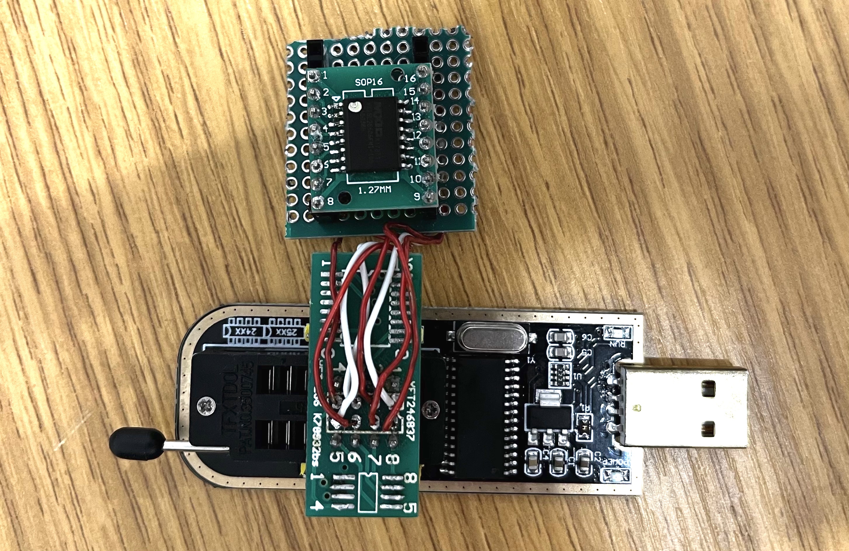
We found that the firmware stored in the SPI flash is neither encrypted nor signed. There are five partitions in the firmware, where the second one contains a Linux operating system. The SMASH shell is provided by /SMASH/msh and it is possible to change it to a different shell by replacing this file.
The Linux operating system also has an I2C kernel module installed, which provides an interface to communicate with the SMBus. However, during our testing in Section 4.1, we found that the API provided by this kernel module is not compatible with the commonly used libi2c in i2c-tool222https://git.kernel.org/pub/scm/utils/i2c-tools/i2c-tools.git/. As the result, in Section 4.1, we opted to write a custom library to use the I2C interface of the BMC and communicate with the VRM.
3.3 Firmware Upgrade
After analysing the firmware, we conclude that it is possible to enable an SSH shell by modifying the firmware. We then started to look for software methods to re-flash the BMC SPI flash chip. We found that the firmware upgrade functionality of the BMC provides a way to do this. There are two interfaces for firmware upgrade: one is through the web interface, the other through the KCS interface.
Through Web Interface
The web interface has a firmware upgrade page that can switch the BMC into upgrade mode and allows the user to upload a BMC firmware update package. To prevents unauthorised user from upgrading the firmware, there is a login portal. The user is authenticated by the BMC. As the BMC is a system independent from the OS running on the CPU, users do not need to have privileged access to the OS to be able to use this method. Besides, this web interface can be accessed remotely through Ethernet. The remote BMC firmware upgrade attack chain described in Section 4.3 uses this method to upgrade the firmware.
Through IPMI-over-KCS Interface
Firmware Upgrade Package
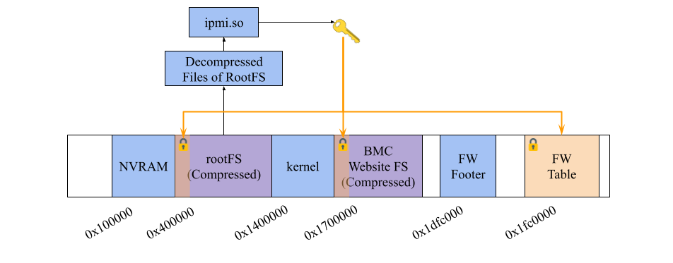
After finding the firmware upgrade interface, the next step is to produce an upgrade package that can be uploaded to the BMC. We started with the analysis of the structure of the upgrade package. Figure 4 shows the layout of a firmware upgrade package. Previous work by [Ecl18] founds that in the firmware upgrade package, there is a region that contains a magic value (ATENs_FW), a half-length CRC checksum, and the length of each section. We call this part the firmware footer. There is also a region containing metadata of the firmware image, including the name of each region and their length and CRC, starting with “[img]”. We refer to this region as firmware table. In the X11 series, the firmware table, the file system header of the root file system and the website files system header are AES-CBC encrypted. However, the files in these regions are not encrypted, but only LZMA compressed. As a result, the key of the AES-CBC encryption can be recovered from the ipmi.so file on the root file system.
With this information, we can modify the firmware and construct a valid firmware upgrade package for the web interface. We discuss firmware repacking in detail in Section 4.2.
3.4 IPMI I2C functionality
When exploring the functionalities of IPMI, we also found that the interface also allows direct sending I2C packets with the ipmitool i2c command. This can be used either through the Ethernet or KCS IPMI channel. The authentication requirement for using IPMI-controlled I2C is the same as those described in Section 3.3. As shown in Section 4.3, we can use this functionality for direct access to the SMBus/PMBus without modifying BMC firmware.
4 Practical Experiments
Finally, using the results from the previous sections, we explain how to construct practical Proof-of-Concept (PoC) attacks for PMFault. Some of our experiments require physical access to the system to understand the hardware configuration (with an overview shown in Figure 5). Note however that physical access is not required when performing PMFault attacks on a real-world system, as the hardware components and connections are identical for a given motherboard model.
4.1 PMBus-based Voltage Control
To understand the configuration and capabilities of using the PMBus to control the CPU voltage, we conducted two experiments. Firstly, we used the “probe and verify” method to find the I2C address of the VRM. Then we tried different ways of sending commands to VRM to change the voltage.
Discovering the VRM Address
Finding the I2C address of the VRM is the first step of PMFault. The easiest way to explore the I2C buses is to use the interface provided by the OS. There are two I2C buses that can be used from the OS running on the CPU: i2c-0 is shown by default, while i2c-1 requires the i2c_i801 kernel module to be loaded. To find all available devices on both I2C buses, we ran the i2cdetect tool on them. We found that there are 12 devices in total connected to the I2C bus. The full list of device addresses can be found in Appendix A.
To then determine which device is a VRM, we use the result of the standard PMBus command, READ_VOUT, as an indicator. The Plundervolt [MOG+20] attack showed that the normal operating voltage of the CPU should be greater than 0.55 V, thus, if the voltage read by READ_VOUT is within this range, it may be a VRM. Of the 12 devices detected, only one device with address 0x20 on I2C bus 1 responded with a value in this voltage range. We hence suspect this device is the VRM. To verify the result, we also used MFR_ADDR_PMBUS (0xE1) command found in the MP2965 datasheet [Mon] to read the PMBus address of the device. The result is 0x20, which confirms our finding.
Changing CPU Voltage with PMBus Commands
Having identified the VRM, one can next attempt to send commands to change the CPU voltage.
In the datasheet of the MP2965 [Mon], we found an “overclocking” procedure that can be used for this purpose. There are two overclocking modes, tracking mode and fix mode. In PMFault, we mainly use the fix mode to set a defined voltage.
In the fix overclocking mode, the VRM uses the VID configured with the PMBus command VOUT_COMMAND and ignores the configuration from the SVID bus. Figure 6 shows the steps of using this mode to change voltage. First, we need to configure two registers: The first one is VOUT_OPERATION; by setting the first bit of this register, we enable PMBus override mode. We also have to set bit 3 of MFR_VR_CONFIG to make the VRM act on these changes. After this, the voltage supplied to the CPU will be changed according to the configuration in VOUT_COMMAND. To send this PMBus command sequence and change the CPU voltage, we wrote a PoC with the libi2c. This PoC can be compiled and run under Linux.
“Stalls” caused by PMBus Commands
The experiments in Section 4.1 also show that the VRM responds to the PMBus commands sent from the CPU. One may thus assume that it would then be straightforward to directly send PMBus commands to change the CPU voltage with this method. However, we found that the CPU stalls after sending the MFR_VR_CONFIG command to actually configure the VRM to use the new voltage. This will make the CPU voltage being kept at the changed value with no way to change it back. This phenomenon raised two questions: Is the CPU stall caused by a crash or a recoverable halt? If it is caused by a recoverable halt, will this protect against targeted undervolting fault injection?
To answer this, we connected a Raspberry Pi to the PMBus to directly control the VRM. The I2C interface to the VRM is exposed with two pins, SDA and SCL. As shown in Figure 5, we connected the I2C interface of the Raspberry Pi to these pins.
In the first experiment, we sent a command to disable overclocking after the stall happens. It appears that with the VRM reconfigured to normal mode, the CPU recovers from the stall situation if the undervolting value is not too low. This shows that the stall is caused by a recoverable halt and not a crash. The second experiment is used to find out if the halt will prevent the fault from happening. In this experiment, we used the CRT-RSA PoC of the Plundervolt attack. With the CPU running this PoC, we used Raspberry Pi to send PMBus commands to produce voltage glitches. We found that with glitches with gradually lower voltage, an exploitable fault happens with the CRT-RSA calculation.
Voltage Control with BMC
Because our attempt of voltage glitching failed with the PoC running on the CPU, we started to look into the BMC-VRM I2C interface. In the BMC firmware dumped in Section 3.1, we found the i2c.ko kernel module, which provides a driver for the I2C interface. However, this module does not implement a standard ioctl() for I2C devices, which is required for using libi2c. This means that the above PoC, which uses this standard I2C library, cannot be used to communicate with this kernel module.
As the kernel module in the firmware did not implement the standard I2C API, we had to find another way to utilize the BMC’s I2C interface. With the help of the I2C driver in the latest Linux kernel [astb, asta], we found that there are 14 I2C interfaces on the AST2400 BMC controller. Each has a set of memory-mapped registers to control the interface. We also found the setup and message sending/receiving sequence of the I2C interface. We then created a small library to directly write these registers and send I2C bus commands from the BMC CPU to the address of the VRM. By monitoring the I2C activity with an oscilloscope (this was only required for debugging and during development), we found that the I2C bus 2 (counted from bus 0) of the BMC has the VRM connected.
4.2 Enabling SSH Access and Firmware Repacking
Modification of the firmware can be used to obtain a root shell on the BMC. With the “Supermicro BMC firmware image decryptor” [Nie20] and a modified version of the “ipmi firmware tool” [Rak15] with added support for X11 images, we were able to extract the firmware encryption key and decrypt the file system header. With these, we can unpack and modify the full root file system.
As described in Section 3.2, /SMASH/msh provides the shell for SSH service. To enable full root shell access, we replaced this file with a shell script with a single line to execute /bin/sh. Besides, as the SSH service is running with root privileges, with the shell redirected to sh, we could obtain a root shell once connected to the SSH.
To repack the image, we modified the “Supermicro BMC firmware image decryptor” tool to add firmware encryption support and constructed a firmware package with a valid footer and firmware table. We successfully tested and installed this modified firmware package both with the web firmware upgrade interface and the IPMI firmware upgrade interface via the AlUpdate tool.
4.3 Attack Chains for PMBus Access
In this section, we discuss three possible attack chains to take over the PMBus with the techniques shown in the previous sections. The attacker can use any of these attack chains and change the CPU voltage to perform PMFault attacks, i.e., to over/undervolt the CPU.
Remote BMC Firmware Upgrade
The first attack chain assumes a malicious insider threat model. This attack chain makes use of the web or IPMI interface through the BMC Ethernet connection. To use this interface, the attacker needs to have access to the BMC management Ethernet port or the shared management Ethernet port eth0 on the system. Besides, the attacker needs to obtain valid credentials to login to the BMC.
In detail, the attacker can first use the method described in Section 4.2 to repack the SMT_X11_163 firmware upgrade package from [bmc] to enable SSH root access to the BMC. Then, they can upload the firmware with the web management interface or the IPMI management interface over Ethernet. With the SSH interface enabled, the attacker can cross-compile the voltage-changing PoC described in Section 4.1 for the BMC, and then upload and execute it to send PMBus commands. We used base64 -d > /tmp/i2c-pmbus-send to upload our exploit code due to the unavailability of the SCP service on the BMC OS.
Local BMC Firmware Upgrade
Similar to the first, this attack chain also involves a firmware upgrade for code execution on the BMC. However, we use the KCS interface discussed in Section 3.3 to upgrade the firmware. The attacker does not require access to the management Ethernet plane, instead, only root privileges on the OS running on the CPU is required. This is e.g., relevant for data centers that host bare metal machines for customers or for malware/ransomware that has obtained root through other exploits.
IPMI Interface
The third attack chain uses the IPMI I2C functionality. An attacker with root access on the CPU OS or access to the management port of the BMC can use this interface to send commands to any I2C device that is connected to the BMC. The command used for sending the raw I2C packets is shown in LABEL:lst:ipmi_cmd. The I2C mapping of this interface is the same as found during the initial investigation in Section 4.1. The VRM is at address 0x20 on bus 2. However, since the last bit of the first packet of I2C indicates the type of operation (read or write), we need to shift the device address left by one bit and set the last bit accordingly when using this interface to control PMBus.
5 Undervolting and Overvolting Attacks
In this section, we show how under/overvolting through the PMBus leads to attacks on SGX and also permanent physical damage to the CPU. The attack requires any flaw that gives a software attacker access to the PMBus. As mentioned in Section 4.3, this can e.g., be a malicious firmware upgrade or the use of the IPMI-to-I2C functionality. The attack is generic in the sense that various flaws can lead to the same outcome: remote fault injection attacks on SGX and bricking the CPU. Figure 7 shows an overview of the attacks.
5.1 Undervolting Attack against Intel SGX
Adversary Model
As mentioned in Section 1.2, we assume a threat model where an attacker (including a malicious insider) has full software access to the system but no (or limited) physical access. More precisely, the attacker has root access to the OS and software access to the BMC via the KCS interface or Ethernet. All attack chains described in Section 4.3 can generally be used under this threat model. It is worth mentioning that the attack that uses ipmitool through the KCS interface does not require knowledge of the BMC credentials. A privileged local user on a compromised host CPU can thus use ipmitool to inject fault into SGX purely from software.
Proof of Concept
We used the same PoC code as Plundervolt/VoltPillager [MOG+20]. Before injecting the voltage glitch, we use the attack chain described in Section 4.3 to gain control of the PMBus.
To start with, we used the multiply operation as the first target, as it is a simple target to fault. By gradually lowering the CPU voltage with the PMBus commands sent by the BMC while running the Plundervolt/VoltPillager PoC on the CPU, we successfully injected faults into the multiply operation (in our experiments at voltage 0.845 V with the CPU running at 2 GHz.
To verify the fault injection also works for encryption operations running in SGX, we ran the CRT-RSA signature PoC from Plundervolt/VoltPillager, with an RSA signature computed inside an enclave using the Intel Integrated Performance Primitives (Intel IPP) cryptography library functions [Cor]. Again, we could obtain faulty signatures as shown in Listing LABEL:lst:faults. Furthermore, we confirmed that these faulty values could be used to factor the RSA modulus and recover the private RSA key using the Lenstra attack [BDL97].
Reproducibility of CRT-RSA Fault Injection
To further evaluate the reproducibility of the attack, we setup an automated testing environment by connecting a Raspberry Pi to an Ethernet port (eth0) and the power button of the motherboard. We ran a Python script to repeat the following steps numerous times:
-
1.
Upload the exploit for controlling the CPU voltage to BMC via an SSH connection.
- 2.
- 3.
-
4.
Stop lowering the CPU voltage when a fault occurs.
-
5.
Record the result and cleanup.
-
6.
If no faulty result is output, the system may have crashed due to too low voltage. In this case, we use the connection to the motherboard power button to reboot the system and wait to allow the system to boot into a stable status.
In total, we conducted 253 tests within 545 min. Of those, faults occurred in 194 tests. 66 of these faulty results could be used to successfully recover the correct RSA private key using the Lenstra attack, which translates to a success rate of 26%. On average, a useful fault could be obtained within 9 minutes.
5.2 Overvolting to Permanently Brick a CPU
Apart from the undervolting attack to extract keys from an SGX enclave, we also discovered another attack, which is an overvolting attack that can permanently destroy the CPU.
Adversary Model
In this attack, as described in Section 1.2, we assume an attacker who has root privilege on the host CPU. For example, this could be in the case that an attacker has placed ransomware on a system and threatens to damage the CPU unless a ransom is paid. Clearly, root should have full control of all software running on the CPU, but should not be able to cause any physical damage to the system. The attack chain described in Section 4.3 using ipmitool with KCS can be used within this threat model.
Proof of Concept
To overvolt the CPU, we firstly configure the MFR_VR_CONFIG register of the VRM to use the 10 mV SVID table. This allows changing the CPU voltage up to 3 V. We also disabled the over-current protection by reconfiguring the MFR_OCP_TOTAL_SET register. Then we used the voltage changing procedure to change the CPU voltage to a value much higher than the normal operating voltage.
We found that this procedure allows changing the CPU voltage up to 2.84 V for 1 ms, which is outside the typical operating range of Intel CPUs. By increasing the voltage beyond the specified operating voltage range (0.55 V–1.52 V) [Cor18] of a 7th Gen Intel E3-1220V6 CPU two times, we permanently destroyed the CPU and left the system in an unbootable state within a few seconds. We successfully repeated the experiment with a second, identical CPU. An example of overvolting is shown in Figure 8.
For environmental and financial reasons, we were satisfied after successfully destroying two CPUs and decided to not perform further experiments in that regard.

6 Evaluation of other Server Motherboards
As we found the PMBus to be a common interface present on server motherboard, we decided to investigate other manufacturers as well. To facilitate larger-scale testing of this, we wrote a tool called PMBusDetect. With this tool, we scan the system for a PMBus connection and try to detect the VRM address. We applied this tool to several other systems, including an ASRock rack motherboard (ASRock E3C246D4I-2T) and a Supermicro X12DPi-NT6 motherboard (kindly provided by Supermicro for testing). We then conducted further analysis of these systems to check if they are vulnerable to any PMBus-related attack.
PMBusDetect Tool for VRM Detection
Based on the VRM detection process mentioned in Section 4.1, we built the PMBusDetect tool to automatically scan all addresses of a specified I2C bus for VRMs. During testing, we found that the implementation of PMBus and usage of the VRM is different between motherboard, and the most stable command to identify a VRM is READ_TEMPERATURE (0x8d). We use the response to this command as an initial indicator to identify whether a VRM is present, and then use the VRM detection process from Section 4.1 to verify the result.
Moreover, as the capabilities and voltage changing sequence can differ between VRM vendor, we added an additional procedure to detect the vendor of the VRM. For this, we use the result of reading ISL_DEVICE_ID (0xad) as an indicator for Intersil VRMs and SVID_VENDOR_PRODUCT_ID (0xbf) for MPS, respectively. Detection based on ipmi i2c is also implemented for detecting the connection between VRM and the BMC as mentioned in Section 4.3. An example output of PMBusDetect with Supermicro X11SSL-CF is shown in Appendix B, while Table 3 shows a summary of the motherboard tested and the scan result for VRMs with PMBusDetect. We are aware that our testing—restricted by (lack of) access to server hardware— only gives a very limited picture of the use of PMBus and VRMs on server hardware. We hence decided to open-source PMBusDetect and build on community efforts in the future to obtain a better view of the PMBus landscape.
6.1 ASRock Power-Down Attack
The ASRock E3C246D4I-2T motherboard uses an Intel Xeon E-2124 CPU with an Intel C246 Chipset and ASPEED AST2500 BMC with login credentials defaulting to ADMIN:ADMIN. We used the PMBusDetect tool together with manual probing and found that the VRM of this motherboard is connected to both the BMC and I2C bus of the CPU. In the following attack, we assume that the attacker is a user on a baremetal server with root access in the OS.
The VRM used on this motherboard is an ISL69138. Because it is made by a different manufacture compared to the MP2955, the voltage changing PMBus command sequence used for the MP2955 does not work with this VRM. Due to lack of documentation of this procedure, we at the moment could not precisely overvolt or undervolt the CPU via the PMBus. Yet, we discovered a new attack to disable the VRM and force power-down the CPU, leaving the system in a (temporary) inoperable state.
PMBusDetect shows that the VRM is at address 0x60 on I2C bus 2 of the host CPU. Different to the findings for the Supermicro X11SSL-CF, this VRM uses PMBus registers on page 0x1 instead of the default 0x0. We then issue the ON_OFF_CONFIG (0x02) and OPERATION (0x01) commands: We configure the OPERATION to “Immediate Off” and set the “source of enable” only to ON_OFF_CONFIG. This results in a immediate power-off of the VRM and crashes the system.
During testing, we found the PMBus is only writable from the CPU with IPMI over KCS interface, but not from the BMC with ipmi i2c commands. As the result, it is not possible for the administrator of the system to remotely configure the VRM back to a normal state. Simply issuing the ipmi powercycle command with IPMI over LAN will leave the system in a infinite boot loop. To recover from this attack, the administrator has to physically power-cycle the system, which might increase downtime in a Denial-of-Service (DoS) scenario.
This shows that PMBus as an attack vector does not only affect Supermicro X11SSL-CF, but also can have impact on servers from other manufacturers. Besides we believe that it might also be possible to conduct CPU bricking attacks if the PMBus voltage changing sequence of Intersil VRM is known. We leave this for future work.
6.2 Other Supermicro X11 Motherboards
We also ran the PMBusDetect tool on X11SPG-TF and X11SSE-F Supermicro server motherboards—in both cases, the VRM was reachable in the default configuration. To test if they are vulnerable to PMFault, we sent PMBus commands through ipmi i2c commands and successfully undervolted them to crash the system. This shows that the attack chain through the IPMI interface is valid on these systems. As the systems were provided by a third party for remote testing, we were not able to attempt overvolting and similar, destructive experiments, but believe these motherboards to be equally affected.
6.3 Supermicro X12 Motherboards
We disclosed the vulnerability to Supermicro in May 2022. They confirmed the issue and also provided a X12 generation Server for further testing. This system, Supermicro X12DPi-NT6, features a dual Intel Xeon Gold 6330 CPU, Intel C621A Chipset, and AST2600 BMC. Our investigation shows that mitigations has already been implemented on this motherboard to break the attack chain of PMFault before we reported the attack to Supermicro. Firstly, the firmware upgrade package is properly signed with RSA and verified during the firmware upgrade process, which prevents malicious firmware uploads to the BMC via IPMI. This breaks the attack chain though firmware upgrade. Secondly, I2C packet filtering has been implemented in the BMC, which prevents IPMI commands to directly send packets to the PMBus. Moreover, our PMBusDetect tool shows that the VR is not connected to the CPU, which prevents an attack directly from the operating system. In conclusion, to the best of our knowledge, we believe that Supermicro X12DPi-NT6 is not directly vulnerable to the attacks described in this paper. However, we note that as-of-yet unknown vulnerabilities might remain in the firmware update process and the complex software stack running on the BMC, which warrants further investigation.
7 Conclusions and Countermeasures
In this paper, we demonstrated two remote attacks that use the PMBus interface to control the CPU voltage. An undervolting attack can be used to inject fault to the SGX enclave of the CPU and e.g., recover a secret key used in cryptography algorithms. The overvolting attack causes permanent damage to the CPU.
The attack affects, to our knowledge, all 11th generation Supermicro systems. It also impacts ASRock (tested with ASRock E3C246D4I-2T), though as described the VRM behaves differently to Supermicro. We suspect that the attack might also affect other vendors (given that BMCs are often similar), but could not further investigate this and thus leave it for future work.
7.1 Server Platform Security and Embedded System Security
We first discuss the security considerations for server platforms. Previous security research on computer platforms were mainly focused on the security of the software (either running on the CPU or the management controller). However, each subsystem on a server platform does not act in isolation. Instead, they may interact with each other via the physical connections on the motherboard. In our attacks, we show that the hardware design of the system with a correctly implemented ipmitool can lead to severe security issues and damage to the system.
Apart from the components on the motherboard, one should also take “plugin” devices into consideration when analysing the security of server platforms. During our investigation of the system, we found that when a Peripheral Component Interconnect Express (PCI-E) device is plugged onto the motherboard, it is also connected to the I2C bus of the motherboard. However, if the firmware of a PCI-E device is compromised, it can gain access to the PMBus to perform the same attacks described in this paper. On E3-1220V6-X11SSL-CF, this connection can be configured with a jumper named JI2C. Although this jumper is disconnected by default, the user may not be aware of the security implications of connecting this jumper.
In summary, the server platform is a system that has multiple components and microcontrollers. The security of the platforms is not only down to ensuring the security of the software running on it, but the overall design of the hardware and embedded systems on the motherboard should also go through a thorough security review. Securing such a system needs collaborative effort of both software developers and hardware engineers.
7.2 SGX Security
Our attack on SGX enclaves shows that a privileged local attacker can inject a fault to the enclave and recover secret information with the server management interface, effectively reviving Plundervolt-like software undervolting attacks on Supermicro X11 motherboards. We also demonstrate that a malicious service provider (e.g., cloud hoster) can use the attack chains described in the paper to break the security guarantee provided by SGX. Moreover, the vulnerability currently cannot be detected/mitigated by SGX attestation, because the BMC and its firmware are not within the scope of SGX attestation.
A supply chain attack is also possible: as the firmware is not securely verified, it is possible for a third party to implant malware into the BMC and later launch remote attacks on SGX and/or damage the CPU. Such a firmware modification is also conceivable while the device is being shipped to the end user. Detecting such attack would be hard, as the firmware of the BMC is stored in a separate flash chip. The software running on the BMC is thus usually out-of-scope of traditional malware detection methods.
7.3 Countermeasures
Overvolting Attack
According to our experiments, PMBus-based overvolting can lead to permanent damage to the CPU and thus permanent DoS of the system.
The fundamental issue that leads to this attack is the lack of a hardcoded voltage limit of the VRM. Simply adding signature verification of the BMC firmware or using secure boot to break the attack chain might not be sufficient to prevent overvolting, as other, future attacks might also yield PMBus access. Besides, configuring software-based PMBus read/write limitations of the VRM through the MFR_PWD_USER command is also insufficient to stop the attack. This is because this features only sets a 16-bit passcode, which is prone to brute force attack. We suggest the following mitigations be implemented for this attack to break the attack chain:
-
1.
In the short term, the user manual of the relevant system(s) should be updated to describe the usage and suggested configuration of the SMBDAT_VRM and SMBCLK_VRM jumpers, if they are present on a specific model.
- 2.
-
3.
Another mitigation would be implementing an I2C filter to detect and block malicious PMBus packets. MFR_VR_CONFIG, which can be used to set a 10 mV VID table, is one of the main commands that need to be blocked. Optionally, other commands that involved in the overclocking procedure could be blocked, however, this may affect users who actually want to use this feature. Such a filter could be implemented in a small microcontroller that listens to the I2C bus and “jams” malicious commands by actively pulling the bus low once the command has been detected but before its transmission has been completed.
PMBus-based SGX Undervolting
To the best of our knowledge, PMFault represents the first attack that directly breaches integrity guarantees in the Intel SGX security architecture through the PMBus interface. We believe that the fix currently deployed by Intel against Plundervolt/V0ltPwn (CVE-2019-11157)—disabling the SVID undervolting interface—is insufficient when a remote attacker can get access to the PMBus through the BMC or I2C interface of the CPU, as is the case for Supermicro X11 motherboards. We note that there might be many other devices connected to the bus, including PCI-E devices like graphic cards. It is thus also possible for a compromised PCI-E device to send malicious commands to control the CPU voltage.
Given the potential impact of our findings regarding fault injection into SGX enclaves, in the short term, we recommend inserting software-based fault injection countermeasures into cryptographic computations in enclaves (e.g., the quoting enclave). However, we note that such fixes can only serve as mitigations, but not fully eliminate this attack vector.
We would like to highlight that in our opinion, this attack surface cannot be easily addressed by jumpers to disconnect the VRM from the SMBus or adding signature verification of the BMC firmware, as we believe that SGX attestation cannot independently verify the relevant system configurations:
- 1.
- 2.
- 3.
This will make it impossible to give SGX assurance of the trust status of the system. We believe that in the long term, appropriate hardware countermeasures inside the CPU package is required: this could on the one hand include continuous monitoring of the received supply voltage, as recently presented by Intel for critical parts of their systems [NT22], and on the other the use of fully-integrated voltage regulators.
Acknowledgements
This research is partially funded by the Engineering and Physical Sciences Research Council (EPSRC) under grants EP/R012598/1, EP/R008000/1, and EP/V000454/1. The results feed into DsbDtech. We would also like to thank Supermicro for providing a X12DPi-NT6 server for further investigation of the issue.
Appendix A i2cdetect Result for Supermicro X11SSL-CF
Appendix B PMBusDetect Result for Supermicro X11SSL-CF
References
- [asta] Aspeed 24XX/25XX I2C Controller Linux Kernel 5.16 Driver. https://elixir.bootlin.com/linux/latest/source/drivers/i2c/busses/i2c-aspeed.c. visited on 2022-09-16.
- [astb] Linux device tree file: aspeed-g4.dtsi. https://github.com/torvalds/linux/blob/133d9c53c9dcbb1b8f317e402e79c44d9eb725c9/arch/arm/boot/dts/aspeed-g4.dtsi#L438. visited on 2022-09-16.
- [BDL97] Dan Boneh, Richard A. Demillo, and Richard J. Lipton. On the Importance of Checking Computations. In Proceedings of Eurocrypt’97, pages 37 – 51, 1997.
- [BECN+06] Hagai Bar-El, Hamid Choukri, David Naccache, Michael Tunstall, and Claire Whelan. The sorcerer’s apprentice guide to fault attacks. Proceedings of the IEEE, 94(2):370–382, 2006.
- [BJKS21] Robert Buhren, Hans-Niklas Jacob, Thilo Krachenfels, and Jean-Pierre Seifert. One Glitch to Rule Them All: Fault Injection Attacks Against AMD’s Secure Encrypted Virtualization. In Proceedings of the 2021 ACM SIGSAC Conference on Computer and Communications Security, CCS ’21, page 2875–2889, New York, NY, USA, 2021. Association for Computing Machinery.
- [bmc] https://drunkencat.net/misc/SupermicroBIOS.html. visited on 2022-11-18.
- [Cor] Intel Corporation. Cryptography for Intel Integrated Performance Primitives Developer Reference—RSA Primitives. https://www.intel.com/content/www/us/en/develop/documentation/ipp-crypto-reference/top/public-key-cryptography-functions/rsa-algorithm-functions/rsa-primitives.html. visited on 2023-01-05.
- [Cor18] Intel Corporation. Intel Xeon Processor E3-1200 v6 Product Family for S Platforms, 01 2018. https://www.intel.co.uk/content/dam/www/public/us/en/documents/datasheets/xeon-e3-1200v6-vol-1-datasheet.pdf. visited on 2022-09-16.
- [CVM+21] Zitai Chen, Georgios Vasilakis, Kit Murdock, Edward Dean, David Oswald, and Flavio D. Garcia. VoltPillager: Hardware-based fault injection attacks against intel SGX enclaves using the SVID voltage scaling interface. In 30th USENIX Security Symposium (USENIX Security 21), pages 699–716. USENIX Association, August 2021.
- [Ecl18] Eclypsium. Insecure firmware updates in server management systems, Sep 2018. https://eclypsium.com/2018/09/06/insecure-firmware-updates-in-server-management-systems/. visited on 2022-09-10.
- [GE17] Maxim Goryachy and Mark Ermolov. How to Hack a Turned-Off Computer, or Running Unsigned Code in Intel Management Engine, November 2017. Black Hat Europe 2017, https://www.blackhat.com/docs/eu-17/materials/eu-17-Goryachy-How-To-Hack-A-Turned-Off-Computer-Or-Running-Unsigned-Code-In-Intel-Management-Engine.pdf. Visited on 2022-01-06.
- [KDK+14] Yoongu Kim, Ross Daly, Jeremie Kim, Chris Fallin, Ji Hye Lee, Donghyuk Lee, Chris Wilkerson, Konrad Lai, and Onur Mutlu. Flipping bits in memory without accessing them: An experimental study of DRAM disturbance errors. In ISCA, 2014.
- [KFG+20] Zijo Kenjar, Tommaso Frassetto, David Gens, Michael Franz, and Ahmad-Reza Sadeghi. V0LTpwn: Attacking x86 Processor Integrity from Software. In USENIX Security ’20, Boston, August 2020. USENIX Association.
- [MIT17] MITRE. CVE-2017-5689, February 2017. https://cve.mitre.org/cgi-bin/cvename.cgi?name=CVE-2017-5689. visited on 2022-01-06.
- [MOG+20] Kit Murdock, David Oswald, Flavio D. Garcia, Jo Van Bulck, Daniel Gruss, and Frank Piessens. Plundervolt: Software-based Fault Injection Attacks against Intel SGX. In Proceedings of the 41st IEEE Symposium on Security and Privacy (S&P’20), 2020.
- [Mon] Monolithic Power Systems, Inc. MP2965 Datasheet. https://www.monolithicpower.com/en/mp2965.html. visited on 2022-09-10.
- [Nie20] Michael Niewöhner. Supermicro BMC firmware image decryptor, 2020. https://github.com/c0d3z3r0/smcbmc. visited on 2022-09-08.
- [NT22] Daniel Nemiroff and Carlos Tokunaga. Whitepaper: Fault Injection Countermeasures, Deployed at Scale. Technical report, 2022.
- [PGC18] Fabien Périgaud, Alexandre Gazet, and Joffrey Czarny. Subverting your server through its BMC: the HPE iLO4 case. In Recon Brussels ’18, 2018.
- [pmb] PMBus Power System Management Protocol Specification, Part II – Command Language. https://470q2hhkn9g15l4bc2btbal1-wpengine.netdna-ssl.com/wp-content/uploads/2022/01/PMBus-Specification-Rev-1-3-1-Part-II-20150313.pdf. visited on 2022-09-11.
- [QWLQ19] P. Qiu, D. Wang, Y. Lyu, and G. Qu. VoltJockey: Breaking SGX by Software-Controlled Voltage-Induced Hardware Faults. In AsianHOST ’19, pages 1–6, 2019.
- [Rak15] Brian Rak. Github repo: ipmi_firmware_tools, 2015. https://github.com/devicenull/ipmi_firmware_tools. visited on 2022-09-15.
- [RR18] Jordan Robertson and Michael Riley. The Big Hack: How China Used a Tiny Chip to Infiltrate U.S. Companies, Oct 2018. https://www.bloomberg.com/news/features/2018-10-04/the-big-hack-how-china-used-a-tiny-chip-to-infiltrate-america-s-top-companies#xj4y7vzkg. visited on 2022-09-19.
- [Supa] Supermicro. X11SSL-CF(-nF) Quick Reference Guide. https://www.supermicro.com/QuickRefs/motherboard/C232/QRG-1782.pdf. visited on 2022-09-13.
- [Supb] Supermicro. X11SSL-CF X11SSL-nF USER MANUAL Revision 1.1. https://www.supermicro.com/manuals/motherboard/C232/MNL-1782.pdf. visited on 2022-09-10.
- [TSS17] Adrian Tang, Simha Sethumadhavan, and Salvatore Stolfo. CLKSCREW: Exposing the perils of security-oblivious energy management. In USENIX Security ’17, pages 1057–1074, Vancouver, BC, August 2017. USENIX Association.
- [TW09] Alexander Tereshkin and Rafal Wojtczuk. Introducing ring -3 rootkits, 2009. Black Hat USA, https://www.blackhat.com/presentations/bh-usa-09/TERESHKIN/BHUSA09-Tereshkin-Ring3Rootkit-SLIDES.pdf. visited on 2023-01-06.
- [Vaz13] Juan Vazquez. Exploiting the Supermicro Onboard IPMI Controller, Nov 2013. https://www.rapid7.com/blog/post/2013/11/15/exploiting-the-supermicro-onboard-ipmi-controller/. visited on 2022-09-12.
- [WS18] Nico Waisman and Matias Sebastian Soler. The Unbearable Lightness of BMC’s. In BlackHat ’18, 2018.